Table of Contents
Advertisement
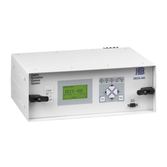
The DECS-400 Digital Excitation Control System is a microprocessor-based controller that provides excitation
control, flexible logic control, and optional power system stabilization for synchronous machines in an
integrated package. The controller provides an analog output to control the DC output of an external rectifier
bridge and monitors machine parameters to control, limit, and protect the synchronous machine from
operating beyond its capability limitations.
The optional Power System Stabilizer is an IEEE-type PSS2A/2B, dual input, "integral of accelerating power"
stabilizer that provides supplementary damping for low-frequency local mode, inter area, and inter unit power
system oscillations.
Setup and initial operation are facilitated by Basler Electric's user-friendly BESTCOMS PC software that
incorporates real time monitoring test analysis, flexible oscillography, trending, and expanded testing
capabilities, including means for performing frequency response tests with a graphic display of results. This
replaces the need for an external Dynamic System Analyzer.
• Microprocessor-based design
• Five Control Modes, with autotracking between modes
- Automatic Voltage Regulation (AVR)
- Field Current Regulation (FCR)
- Var Control
• 0.20% Voltage Regulation Accuracy
• Two pre-position set points for each mode
• Two Programmable Analog Outputs
• Setup from Front Panel HMI or by PC (local or remote)
• 40 Standard Stability Settings
• Time synchronization using IRIG or NTP (via Ethernet)
• Optional Integral Power System Stabilizer
- Dual input, integral of accelerating power (IEEE PSS2A/2B)
- Customer selectable speed-only sensing
- Optional Frequency Based Operation
• Customizable Stability Setting with two PID setting groups
• Reactive Droop, Line Drop Compensation
• Generator Voltage Soft-Start during Buildup
• Real Time Metering for 19 Generator Parameters
• Voltage Matching
• Autotracking with Optional Backup DECS-400
• Flexible Remote Set point Control
- Contact inputs
- Proportional Analog input, ±10 Vdc or 4-20 mA
- Digital Communications
Local RS-232, ASCII, Modem Capabilities
RS-485, Modbus™, RJ-45 Ethernet
(continued on page 2)
Interface for setting and communicating with Basler products
Request BESTCOMS-DECS400
ADDITIONAL INFORMATION
INSTRUCTION MANUAL
FEATURES
- Power Factor (PF)
- Field Voltage Regulation (FVR)
- Two wattmeter power measurement
- Generator or Motor control modes
®
WINDOWS
SOFTWARE
Request Publication 9369700990
P. O. BOX 269 HIGHLAND, ILLINOIS, U.S.A. 62249 PHONE 618-654-2341 FAX 618-654-2351
DECS-400 Digital Excitation Control System
DECS-400
Digital Excitation
Control System
Description and
Pages 2 through 6
FEATURES and
FUNCTIONS
Pages 6 through 9
FRONT VIEW
and DIMENSIONS
Page 9
INTERCONNECT
DIAGRAM
Page 10
Pages 10 and 11
CUTOUT and ORDERING
Page 12
SZF-5
9-10
Advertisement
Table of Contents

Related Manuals for Basler DECS-400


Summary of Contents for Basler DECS-400
-
Page 1: Specifications
Digital Excitation Control System The DECS-400 Digital Excitation Control System is a microprocessor-based controller that provides excitation control, flexible logic control, and optional power system stabilization for synchronous machines in an integrated package. The controller provides an analog output to control the DC output of an external rectifier bridge and monitors machine parameters to control, limit, and protect the synchronous machine from operating beyond its capability limitations. - Page 2 DC power to the main or exciter field of the generator. Because of its high level of flexibility and reliability, the DECS-400 is suitable for use in single or dual controller systems on virtually any synchronous machine.
- Page 3 ±10 Vdc, 0-10 Vdc, or 4-20 milliamperes dc Meter Drivers Two programmable 4 to 20 mA analog meter drivers. Meter side isolated from DECS-400. Programmable to meter field voltage or current, generator voltage or current, bus voltage, generator or bus frequency, active power, reactive power, apparent power, power factor, field temperature, tracking error, position indication and PSS parameters.
- Page 4 DECS-400 Digital Excitation Control System SPECIFICATIONS, continued IRIG-B Time Sync Standard: 200-98, Format B002, Demodulated (dc level-shifted digital signal) or NTP via Ethernet Regulation Accuracy AVR Mode Voltage regulation ±0.2% over the load range, at rated power factor and constant generator frequency.
- Page 5 DECS-400 Digital Excitation Control System SPECIFICATIONS, continued Summing Point Type OEL Limiter response time is less than three cycles. On-Line Level One – Highest current level (instantaneous) set point adjustable from 0 to 11,999Adc in 0.1% increments of the rated field current. Limiting occurs for a time period ranging from 0 to 60 seconds, settable in 1 second increments.
- Page 6 Operating Temperature: -40 to 60°C (-40 to 140°F) Storage Temperature: -40 to 85°C (-40 to 185°F) Physical Weight: 6.1 kg (13.5 lb) Size: See Figure 1 on page 9 for DECS-400 dimensions. FEATURES/FUNCTIONS Voltage Regulation Two PID Setting Groups The DECS-400 regulates the generator RMS voltage to The DEC-400 provides for two sets of PID settings to within 0.20% from no-load to full-load, utilizing digital...
- Page 7 This allows the DECS-400 to be config- inverse time characteristic. Two current levels and a ured for multiple system and application needs.
- Page 8 If any of these events The DECS-400 is also designed to automatically track occurs, the DECS-400 will log that event with a date a second DECS-400 unit using dedicated communica- and time stamp using IRIG B or NTP and an internal tion ports on the two units.
- Page 9 Ethernet communication is another standard feature saved by the DECS-400. available on the DECS-400 via an RJ-45 port. This pro- Real Time Monitoring tocol supports Modbus TCP in 10 Base T transmission The DECS-400 also provides for real time monitoring speeds.
- Page 10 Figure 2 - Typical AC Connection Example BESTCOMS SOFTWARE The DECS-400 is supplied with BESTCOMS PC-based software to facilitate system setup and testing. As shown in the Protection screen, below left, choices are made using drop-down screens, and parameters are familiar.
- Page 11 Real Time Monitoring function illustrated in the Analysis screen, above right. BESTCOMS for the DECS-400 also incorporates greater “Windows” functionality, as shown in the screen shot below. The screen simultaneously displays the systems status and alarms window, other available systems screens using the familiar Explorer View, along with other screens, such as the metering display, the protection screen and the UEL settings screen shown.
- Page 12 • The IDP-800 Interactive Display Panel is a high-resolution, 7.5 inch (diagonal), color touch screen HMI that permits the operator to monitor Basler Electric's DECS-400 excitation systems status, perform control operations, and make routine adjustments to various set points. This next generation HMI can be placed locally on the exciter cabinets or remotely in a control room, via two-wire RS-485 (4000 feet maximum distance from DECS) or RJ-45 Ethernet communication.
Need help?
Do you have a question about the DECS-400 and is the answer not in the manual?
Questions and answers