
Related Manuals for Surna 24-1

Summary of Contents for Surna 24-1
- Page 1 303.993.5271 Surna Commercial Chiller Operating & Maintenance Manual Models: 24-1, 42-1, 60-1, 90-3, 120-3 Revised: February 2015...
-
Page 3: Table Of Contents
Warranty Information Limited Warranty Limitation of Liability Warranty Disclaimer Product Suitability Service Under Warranty Service NOT Under Warranty Warnings Safety Symbols Surna Chiller Safety Guide Parts List Installation Instructions Location Electrical Plumbing Plumbing Tips Operations Instructions Temperature Settings System Maintenance Instructions... -
Page 4: Warranty Information
Note: Extended warranty for parts, labor and shipping are available for purchase for a nominal fee. Contact Surna within 15 days of your chiller’s arrival if you would like to purchase an extended warranty. -
Page 5: Service Under Warranty
Service Under Warranty This product is warranted by Surna against defects due to fault in workmanship or materials. If the product has been damaged under normal use, it will be entitled to warranty service of the type described and within the timeframes outlined. -
Page 6: Warnings
Surna Chiller Safety Guide Consult with an electrician before attempting electrical installation. Using the Surna Chiller equipment in a manner Please read the information in this document carefully prior to attempting the installation, not described in this manual may void its warranty. - Page 7 DO NOT remove the grounded connection under the product warranty. while power is being supplied to the Surna Chiller equipment. Doing so presents an electric shock hazard to users and service personnel. DO NOT operate the Surna Chiller without an appropriate mixture of Propylene Glycol.
-
Page 8: Parts List
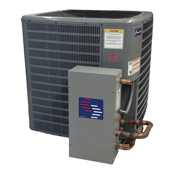
Surna Chiller Parts List Below is a list of all parts provided with each Surna Chiller system. 1. Surna Chiller Product Manual 2. Chiller Unit 3. Strainer 4. Flow Meter 2. Chiller Unit 4. Flow Meter 3. Brass Strainer (front and side view) -
Page 9: Installation Instructions
Installation Instructions Location Plumbing Only install the Surna Chiller equipment on a flat, IMPORTANT: You must use a mixture of Propylene level surface. Acceptable surfaces include con- Glycol and water in your reservoir. Your crete slabs, A/C pads, or pressure treated wood. -
Page 10: Plumbing Tips
Spa tubing can be glued with PVC glue or PVC fitting. In either case, we recommend using piping/tubing that is sized 1 size larger that the chiller water connections provided. Flow Diagram Single pump layout. Consult Surna if your layout requires multiple pumps or chillers. - Page 11 Installation Connections Installation Connections A – Water Inlet B – Water Outlet C – Electrical Panel D – Power Connections (beneath contactor) E – Cable Routing Port F – Delay Timer 2, 3.5 & 5-Ton Power 7.5 & 10-Ton Power Grounding Power Connectors NOTE:...
-
Page 12: Operations Instructions
Operation Instructions Temperature Settings System Maintenance Instructions and After you have made all of the appropriate Recommendations electrical and plumbing connections per the instructions provided above, you may power on the chiller unit and set your desired temperature • ALWAYS maintain a clean condensing coil using the following procedure: for maximum efficiency. - Page 13 glycol/water mixture may cause system inefficiencies or damage to the evaporator, which is not covered under warranty. • NEVER set the chiller below 45°F (7°C) or risk freezing the evaporator, which is not covered under warranty. • Only use properly sized breakers and wiring with an appropriate ampacity or damage to the compressor could occur.
-
Page 14: System Specifications
System Specifications... - Page 15 10-Ton Chiller Chiller Control Panel Connections Control Panel Components A – Control Panel Exterior B – Heat Exchanger C – Temperature Controller D – Thermal Expansion Valve E – Flow Switch F – Low Pressure Switch G – Fan Cycle Switch *High Pressure Switch located inside unit 5-Ton Chiller Control Panel Connections...
- Page 16 10-ton Chiller Wiring Diagram...
- Page 17 2-7.5 ton Chiller Wiring Diagram...
-
Page 18: Troubleshooting
Troubleshooting sure you are getting 24VAC across the sensor while sufficient water is flowing. If there is no voltage across the sensor leads with a This unit is equipped with safety sensors that may proper flow-rate, then the sensor needs to be include high and low pressure sensors for the replaced. -
Page 19: Fan Turns On And Off, Even Though
Fan turns on & off even calling for cooling. If there is not 240VAC on each side, the relay is malfunctioning and though the compressor is needs to be replaced. running QUALIFIED SERVICE PERSONNEL ONLY: there is voltage across the relay when the 1. - Page 20 303.993.5271 info@surna.com surna.com 1780 55th Street Suite A, Boulder, CO 80301...
Need help?
Do you have a question about the 24-1 and is the answer not in the manual?
Questions and answers