Table of Contents
Advertisement
Service
Manual
AMPLIFIER
GM-1006
VEHICLE
DESTINATION
PONTIAC AZTEK U.S.A. , CANADA
CONTENTS
1. SAFETY INFORMATION............................................2
2. EXPLODED VIEWS AND PARTS LIST ......................2
3. SCHEMATIC DIAGRAM.............................................4
4. PCB CONNECTION DIAGRAM................................10
5. ELECTRICAL PARTS LIST........................................14
PIONEER CORPORATION
PIONEER ELECTRONICS SERVICE INC.
Haven 1087 Keetberglaan 1, 9120 Melsele, Belgium
PIONEER EUROPE N.V.
PIONEER ELECTRONICS ASIACENTRE PTE.LTD. 253 Alexandra Road, #04-01, Singapore 159936
C PIONEER CORPORATION 2000
GM
PRODUCED AFTER
OCTOBER 2000
4-1, Meguro 1-Chome, Meguro-ku, Tokyo 153-8654, Japan
P.O.Box 1760, Long Beach, CA 90801-1760 U.S.A.
E
F
G
H
12
11
10
9
8
7
6
5
4
3
2
1
A
D
C
B
A
B
12
11
10
9
8
7
6
5
4
3
2
1
ZG
PART No.
ID No.
10422043
6. ADJUSTMENT .........................................................17
7. GENERAL INFORMATION.......................................18
7.1 DIAGNOSIS .......................................................18
7.1.1 DISASSEMBLY ..........................................18
8. SPECIFICATIONS .....................................................19
K-ZZS. APR. 2000 Printed in Japan
ORDER NO.
CRT2522
X1H/UC
PIONEER MODEL No.
GM-1006ZG/X1H/UC
Advertisement
Table of Contents

Related Manuals for Pioneer GM-1006ZG


Summary of Contents for Pioneer GM-1006ZG
-
Page 1: Table Of Contents
PIONEER ELECTRONICS SERVICE INC. P.O.Box 1760, Long Beach, CA 90801-1760 U.S.A. Haven 1087 Keetberglaan 1, 9120 Melsele, Belgium PIONEER EUROPE N.V. PIONEER ELECTRONICS ASIACENTRE PTE.LTD. 253 Alexandra Road, #04-01, Singapore 159936 C PIONEER CORPORATION 2000 K-ZZS. APR. 2000 Printed in Japan... -
Page 2: Safety Information
GM-1006ZG 1. SAFETY INFORMATION This service manual is intended for qualified service technicians; it is not meant for the casual do-it-yourselfer. Qualified technicians have the necessary test equipment and tools, and have been trained to properly and safely repair complex products such as those covered by this manual. - Page 3 GM-1006ZG NOTE: - Parts marked by “*” are generally unavailable because they are not in our Master Spare Parts List. ∇ mark on the product are used for disassembly. - Screws adjacent to EXTERIOR SECTION PARTS LIST Mark No. Description Part No.
-
Page 4: Schematic Diagram
GM-1006ZG 3. SCHEMATIC DIAGRAM 3.1 OVERALL CONNECTION DIAGRAM(GUIDE PAGE) Note: When ordering service parts, be sure to refer to “EXPLODED VIEWS AND PARTS LIST” or “ELECTRICAL PARTS LIST”. MOTHER UNIT Large size SCH diagram Guide page Detailed page... - Page 5 GM-1006ZG...
- Page 6 GM-1006ZG...
- Page 7 GM-1006ZG...
- Page 8 GM-1006ZG...
- Page 9 GM-1006ZG...
-
Page 10: Pcb Connection Diagram
GM-1006ZG 4. PCB CONNECTION DIAGRAM 4.1 MOTHER UNIT NOTE FOR PCB DIAGRAMS 1. The parts mounted on this PCB include all necessary parts for several destination. For further information for respective destinations, be sure to check with the schematic diagram. - Page 11 GM-1006ZG SIDE A...
- Page 12 GM-1006ZG MOTHER UNIT...
- Page 13 GM-1006ZG SIDE B...
-
Page 14: Electrical Parts List
GM-1006ZG 5. ELECTRICAL PARTS LIST NOTE: - Parts whose parts numbers are omitted are subject to being not supplied. - The part numbers shown below indicate chip components. Chip Resistor RS1/_S___J,RS1/__S___J Chip Capacitor (except for CQS..) CKS.., CCS.., CSZS..=====Circuit Symbol and No.===Part Name Part No. - Page 15 GM-1006ZG =====Circuit Symbol and No.===Part Name Part No. =====Circuit Symbol and No.===Part Name Part No. ------ ------------------------------------------ ------------------------- ------ ------------------------------------------ ------------------------- RS1/10S102J RS1/10S122J RS1/10S102J RS1/10S332J RS1/10S474J RS1/10S332J RS1/10S222J RS1/10S152J RS1/10S222J RS1/10S152J RS1/10S432J RS1/10S753J RS1/10S432J RS1/10S753J RS1/10S820J RS1/10S122J RS1/10S820J RS1/10S122J RS1/10S102J...
- Page 16 GM-1006ZG =====Circuit Symbol and No.===Part Name Part No. =====Circuit Symbol and No.===Part Name Part No. ------ ------------------------------------------ ------------------------- ------ ------------------------------------------ ------------------------- RS1/10S182J CKSYB104K50 RS1/10S470J CKSYB104K50 RS1/10S470J CKSYB184K25 RS1/10S272J CKSYB184K25 RS1/10S472J CKSYB153K50 RS1/10S103J CKSYB153K50 CKSQYB563K50 CAPACITORS CKSQYB563K50 CKSQYB273K50 CCSQCH181J50 CKSQYB273K50 CCSQCH181J50...
-
Page 17: Adjustment
GM-1006ZG =====Circuit Symbol and No.===Part Name Part No. ------ ------------------------------------------ ------------------------- CEAS331M16 CKSQYB103K50 CEAS331M16 CKSQYB103K50 CEJA221M6R3 CEJA1R0M50 CEJA1R0M50 CCSQCH101J50 CCSQCH101J50 CCSQCH101J50 CCSQCH101J50 CCSQCH101J50 CCSQCH101J50 CCSQCH101J50 CCSQCH101J50 CCSQCH101J50 CCSQCH101J50 CCSQCH101J50 CCSQCH101J50 CCSQCH101J50 CCSQCH101J50 CCSQCH101J50 CCSQCH101J50 6. ADJUSTMENT There is no information to be shown in this chapter. -
Page 18: General Information
GM-1006ZG 7. GENERAL INFORMATION 7.1 DIAGNOSIS 7.1.1 DISASSEMBLY Removing the Case (not shown) Removing the Mother Unit Remove the ten screws and then remove the Heat Sink. (Fig.1) Remove the five screws and then remove the Mother Unit. (Fig.2) Fig.1 Heat Sink Fig.2... -
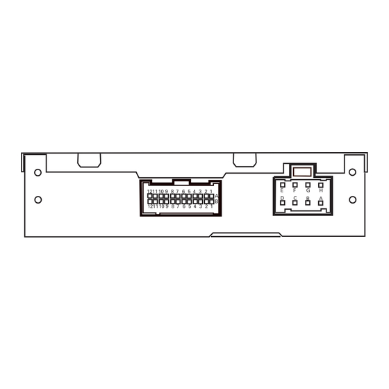
Page 19: Connector Function Description
GM-1006ZG 7.1.2 CONNECTOR FUNCTION DESCRIPTION Subwoofer L- Right Rear In- AMPSENSE Subwoofer L+ Right Rear In+ Subwoofer R- Left Rear In- Subwoofer R+ Left Rear In+ Rear Quarter L- Right Front In- AMP Enable Rear Quarter L+ Right Front In+...
Need help?
Do you have a question about the GM-1006ZG and is the answer not in the manual?
Questions and answers