Table of Contents
Advertisement
Electro-Magnetic Compatibility (EMC)
This product complies with EC Directive 2004/108/EC
when installed and used in accordance with the relevant
instructions.
Service and Technical Support
PLEASE CONTACT YOUR NEAREST DISTRIBUTOR
If unknown then fax: 44 (0) 1453 733322
© Copyright RDS Technology Ltd 2005
Document number
S/DC/500-10-463: Issue 1 : 24/1/05
\UK463-1.DOC
User Guide
"SPRAYMASTER 200"
Sprayer Monitor / Controller
Operation
Software Reference WZ402-002 rev.02
1
Advertisement
Table of Contents

Related Manuals for RDS SPRAYMASTER 200


Summary of Contents for RDS SPRAYMASTER 200
- Page 1 Service and Technical Support PLEASE CONTACT YOUR NEAREST DISTRIBUTOR If unknown then fax: 44 (0) 1453 733322 © Copyright RDS Technology Ltd 2005 Document number S/DC/500-10-463: Issue 1 : 24/1/05 \UK463-1.DOC User Guide “SPRAYMASTER 200”...
-
Page 2: Table Of Contents
SPRAYMASTER 200 Contents Overview_________________________________________3 Area Compensation Interface (ACI)..............3 System Components ..................4 Instrument Facia and Controls ................5 Operation ________________________________________6 Channel Selection....................6 Startup Routine- the "Startup Wizard"..............6 2.2.1 Sprayers with Flow sensor only ............6 2.2.2 Sprayers with Pressure sensor only ..........7 2.2.3 Sprayers with both Pressure sensor and Flow sensor ......8... -
Page 3: Overview
SPRAYMASTER 200 Overview The RDS Spraymaster 200 is designed for the accurate application of liquid spray products proportional to the forward speed of the vehicle, suitable for manual and electrically operated sprayers. The system will work as either a pressure or flow based controller. -
Page 4: System Components
SPRAYMASTER 200 System Components Figure 1 Flow Sensor Pressure Sensor (4 - 20mA) Pressure Control Valve Speed Sensor (alternative 7-way Connector installation To Sprayer Control Valves Serial Interface (ACI) Sprayer Switchbox 'Terminator' Junction Box Forward Speed Power Sensor Supply Cable... -
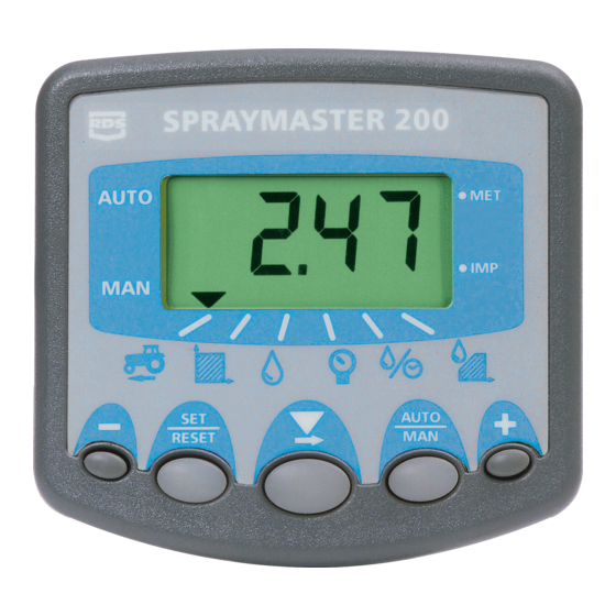
Page 5: Instrument Facia And Controls
SPRAYMASTER 200 Instrument Facia and Controls The five switches control all functions. The power on/off switch is located on the rear of the instrument. Figure 2 Channel Indicator Control Mode Cont. = In-work Indicator Flashing = Out of work Forward Speed... -
Page 6: Operation
The display will prompt you for the new settings. Refer to the appropriate section below. NOTE 1:The Spraymaster 200 is also designed to accommodate the operating requirements of specialist sprayers such as vineyard sprayers in particular. With such installations, the instrument can be configured as part of the startup routine, to also prompt the operator to select the flow sensor and the boom configuration in use. -
Page 7: Sprayers With Pressure Sensor Only
SPRAYMASTER 200 2.2.2 Sprayers with Pressure sensor only In this case the "Startup Wizard" will prompt you to select the following (although see Note 1 above), (i) Set (or confirm) the desired target rate. To change the target rate, press the "+"... -
Page 8: Sprayers With Both Pressure Sensor And Flow Sensor
2.2.3 Sprayers with both Pressure sensor and Flow sensor The Spraymaster 200 system can include both a pressure sensor and a flow sensor, giving you the choice of regulation mode at startup. In this case the "Startup Wizard" will prompt you to select the following (although see Note 1 above), Target Rate (ref. -
Page 9: Rate Display - Channel 6
SPRAYMASTER 200 Rate Display - Channel 6 When in work, channel 6 displays the actual application rate. Press and hold the key at any time to view the programmed Target Rate. 2.3.1 Automatic Rate Control Figure 3: Rate Mode Indicators... -
Page 10: Target Rate Adjustment After Startup
SPRAYMASTER 200 2.3.3 Target Rate Adjustment after Startup At any time in or out of work, you can adjust the target rate. With channel 6 displayed, press and hold the key, and adjust the rate up or down using the '+' / '-' keys. -
Page 11: Forward Speed Display - Channel 1
SPRAYMASTER 200 Forward Speed Display - Channel 1 Channel 1 displays the current forward speed. The instrument defaults to this channel after the "Startup Wizard" routine is completed. Forward speed is measured via a sensor suitably mounted to a wheel hub or a convenient location to the vehicle drivetrain. -
Page 12: Area Override And Part Width
SPRAYMASTER 200 2.5.2 Area Override and Part Width There are two options depending on the installation. (i) Area Compensation Interface An Area Compensation Interface (ACI) connects between the Spraymaster and the sprayer switchbox. It detects which boom sections are on/off in order for the instrument to calculate the actual working width and apply the correct rate. -
Page 13: Volume Applied Display - Channel 3
SPRAYMASTER 200 Volume Applied Display - Channel 3 2.6.1 View/Reset Volume Totals Channel 3 displays the volume applied, and is displayed either in litres or gallons according to the units selected in the CAL Mode. There are two memory registers - a 'Part' total and a 'Full' Total, which can be independently reset. -
Page 14: Pressure Display - Channel 4
SPRAYMASTER 200 Pressure Display - Channel 4 The actual pressure is displayed (bar/psi according to the units selected in the CAL Mode) if a pressure sensor is installed, otherwise this channel is skipped. Flow Rate Display - Channel 5 2.8.1... -
Page 15: Flow Calibration
SPRAYMASTER 200 Flow Calibration 2.9.1 Initial Calibration - The Jug Test To calibrate the output, you should perform an initial jug test, using a simulated forward speed and target rate set to match the intended speed and application rate in the field. -
Page 16: Full-Tank Calibration
SPRAYMASTER 200 2.9.2 Full-tank Calibration The jug test is not the most accurate method of calibration particularly for flow-regulated systems, as the test volume is relatively small. It is therefore recommended to subsequently prove the accuracy by performing a full-tank calibration out on the field, and 'fine-tuning' the Flow sensor factor / Nozzle factor. -
Page 17: Functions Summary
SPRAYMASTER 200 Functions summary... - Page 18 SPRAYMASTER 200 Issue 1: 24/1/05 Original Issue...
Need help?
Do you have a question about the SPRAYMASTER 200 and is the answer not in the manual?
Questions and answers