Table of Contents
Advertisement
Electro-Magnetic Compatibility (EMC)
This product complies with EC Directive 2004/108/EC
when installed and used in accordance with the relevant
instructions.
Service and Technical Support
PLEASE CONTACT YOUR NEAREST DISTRIBUTOR
If unknown then fax: 44 (0) 1453 733322
© Copyright RDS Technology Ltd 2006
Document number
S/DC/500-10-464:
Issue 1e : 7/4/06
\UK464-1e.DOC
User Guide
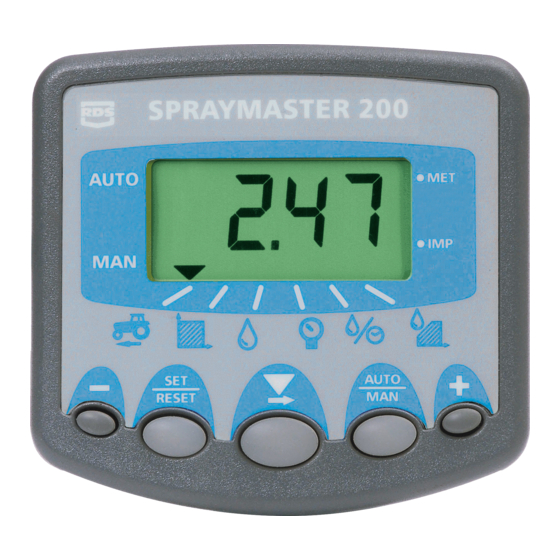
"SPRAYMASTER 200"
Sprayer Monitor / Controller
Installation and Calibration
Software Reference WZ402-002 rev.02
1
Advertisement
Table of Contents

Related Manuals for RDS SPRAYMASTER 200

Summary of Contents for RDS SPRAYMASTER 200
- Page 1 Service and Technical Support PLEASE CONTACT YOUR NEAREST DISTRIBUTOR If unknown then fax: 44 (0) 1453 733322 © Copyright RDS Technology Ltd 2006 Document number S/DC/500-10-464: Issue 1e : 7/4/06 \UK464-1e.DOC User Guide “SPRAYMASTER 200”...
-
Page 2: Table Of Contents
SPRAYMASTER 200 Contents Installation - Overview ____________________________3 Base Kit ......................4 Flow-and/or Pressure-based Plumbing............5 Terminator ......................6 Cutout Switch/ACI ....................7 Calibration _______________________________________8 Boom/Cutout Switch Setup ................8 2.1.1 Enable Single Boom Configuration (Standard) .........8 2.1.2 Enable Multiple Boom Configuration..........8 2.1.3 Select Default Boom ................8 2.1.4... -
Page 3: Installation - Overview
SPRAYMASTER 200 Installation - Overview Flow Sensor Figure 1 Pressure Sensor (4 - 20mA) Pressure Control Valve Speed Sensor (alternative 7-way Connector installation) To Sprayer Control Valves Serial Interface (ACI) S/AC/327-1-098 Sprayer Switchbox 'Terminator' Junction Box S/AC/327-1-091 Forward Speed Power... -
Page 4: Base Kit
SPRAYMASTER 200 The Spraymaster 200 can be retrofitted to almost any make or model of sprayer - self-propelled, trailed or demountable, and configured for either flow-based or pressure-based regulation. It is therefore, supplied as a modular system comprising a Base Kit, plus individual kits specified as required for the particular installation, e.g. -
Page 5: Flow-And/Or Pressure-Based Plumbing
SPRAYMASTER 200 Flow-and/or Pressure-based Plumbing Figure 2 illustrates the general plumbing arrangement for the RDS components. [1] General installation instructions are included in the individual kits. Please refer to these as required. Any additional instructions specific to a Spraymaster installation are given in section 1.3. -
Page 6: Terminator
SPRAYMASTER 200 Terminator Figure 3 Additional information not covered by the individual kit instructions The "Terminator" is the central junction box to which all other components are connected, including the power supply. NOTE: The Terminator is not sealed. It must be located where it will be protected from... -
Page 7: Cutout Switch/Aci
SPRAYMASTER 200 Reverse Polarity and Power LED The head unit has reverse polarity protection and therefore will not be damaged if you inadvertently have the power supply connections reversed. The LED on the Terminator PCB will not light when the 0V and +V connections are reversed. -
Page 8: Calibration
SPRAYMASTER 200 Calibration Boom/Cutout Switch Setup Boom configuration enables the instrument to automatically recognize the correct number of nozzles in use at any moment in time. 2.1.1 Enable Single Boom Configuration (Standard) Cal Mode 3 ( + Power-up ) - Channel 3: Setting = '[FuLL]', '1''... -
Page 9: Set No. Of Nozzles Per Section
SPRAYMASTER 200 2.1.4 Set No. of Nozzles per Section Cal Mode 1 ( + Power-up ) - Channel 6: Default = '0' For single section sprayers fitted with a simple cutout switch, the number displayed is the total no. of nozzles for the boom. -
Page 10: Pressure-Based Setup
SPRAYMASTER 200 (iii) Pressure and flow sensor input. If the pressure sensor gain is set >0, and one or more flow sensor factors are set >0, then you can select either 'PrESS' or 'turb' using the '+' and '-' keys. -
Page 11: Manually Adjust The Pressure Sensor Gain Factor
SPRAYMASTER 200 Adjust the displayed pressure using the ‘+/-’ buttons to make it agree with the external gauge reading. 10. Press the button, the display will show ‘donE’ briefly, followed by ‘GAIN’. 11. The ‘GAIN’ calibration factor can be viewed by pressing and holding button. -
Page 12: Adjust Nozzle Flow Rate And Reference Pressure
SPRAYMASTER 200 2.3.3 Adjust Nozzle Flow Rate and Reference Pressure Cal Mode 1 ( + Power-up ) - Channel 4: Default - see table 1). This channel allows you to set the default nozzle and set the correct nozzle flow rate for a given reference pressure following a jug test. -
Page 13: Flow-Based Setup
SPRAYMASTER 200 Flow-based Setup 2.4.1 Enable / Adjust Flow Sensor Cal Factor Cal Mode 3 ( + Power-up ) - Channel 4: Default - All factors zero). To enable flow-based regulation, at least one cal factor must be set > 0. -
Page 14: Set No. Of Sensed Nozzles
SPRAYMASTER 200 2.4.3 Set No. of Sensed Nozzles Cal Mode 3 ( + Power-up ) - Channel 5: Default = This only needs to be set if an ACI and a flow sensor is installed. Normally the sensed flow is for the full boom width, but in some installations for practical reasons, it may only be the flow to a particular boom section. -
Page 15: Minimum Pulse Width
SPRAYMASTER 200 2.5.2 Minimum Pulse Width Cal Mode 2 ( + Power-up ) - Channel 3 This sets the minimum pulse length (milliseconds x 4) driving the flow control valve. The pulses becomes shorter as the application rate nears the target rate. -
Page 16: Speed Sensor Setup
SPRAYMASTER 200 Speed Sensor Setup Cal Mode 1 ( + Power-up ) - Channel 1 In order to display the correct speed and accumulate distance correctly, the instrument must be programmed with the correct Speed Sensor Factor (SSF). This is the distance travelled between pulses received from the sensor. -
Page 17: Number Of Sensor Magnets
Carry out this test whenever soil conditions or wheel sizes change. (iv) If an RDS Radar sensor is installed, the Speed Sensor Factor is 0.008 m (or 0.312 inches). If the calibration factor works out at over 2.000 m (78.78 inches), consider fitting additional magnets. -
Page 18: Example Calculation 1
SPRAYMASTER 200 Example Calculation 1 The tractor is fitted with a single-magnet propshaft sensor. The measured distance for 10 rotations of the propshaft is 17'-6". Convert the distance to inches :- (17' x 12")+6" = 210" Divide by 10 (magnet pulses) to give the calibration factor:- 210" / 10 = 21"... -
Page 19: Other Settings
SPRAYMASTER 200 Other Settings 2.7.1 Set Step % in Automatic Mode Cal Mode 2 ( + Power-up ) - Channel 6 In manual mode the '+' and '-' keys drive the valve directly. In automatic mode the target application rate is adjusted in % steps. -
Page 20: Functions Summary
SPRAYMASTER 200 Functions summary... - Page 21 SPRAYMASTER 200 Issue 1: 24/1/05 Original Issue 1b: 1/2/05 ref. p.3, 4, 6 : S/AC/327-1-091 now separate parts:- S/AC/327-1-008 + S/CB/327-17-010 Issue 1c 23/5/05 Revised section 2.3.1 Issue 1d 3/3/06 Parts list revision: p.3, 4 Issue 1e 7/4/06 2.7.2 - correction...
Need help?
Do you have a question about the SPRAYMASTER 200 and is the answer not in the manual?
Questions and answers