Table of Contents
Advertisement
Advertisement
Table of Contents

Related Manuals for Pfeiffer TC400

Summary of Contents for Pfeiffer TC400
- Page 1 Betriebsanleitung • Operating Instructions Electronic Drive Unit TC 400...
-
Page 2: Table Of Contents
Cross-linking via the connection RS485 ..... 12 The Pfeiffer Vacuum parameter set ..... . . 12 General . -
Page 3: About This Manual
1 About this manual 1.1 Validity This operating manual is for customers of Pfeiffer Vacuum. It describes the func- tioning of the designated product and provides the most important information for safe use of the unit. The description follows applicable EU guidelines. All informa- tion provided in this operating manual refer to the current state of the product's de- velopment. -
Page 4: Safety
• Power supply: The turbopump power supply must apply to the requirements of double insulation between mains input voltage and operating voltage according to the regulations of IEC 61010 and IEC 60950. Therefore Pfeiffer Vacuum recom- mends to use exclusively original-power packs and -accessories. Only in this case Pfeiffer Vacuum is able to guarantee the compliance of the European and North American guidelines. -
Page 5: Improper Use
To correctly identify the product when communicating with Pfeiffer Vacuum, al- ways have the information from the rating plate available. 3.2 Range of application Pfeiffer Vacuum electronic drive units TC 400 must be installed and operated in the following ambient conditions. Installation location... -
Page 6: Function
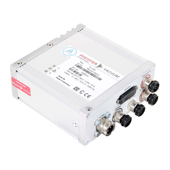
High Density D-sub 26 pole female socket for the connection of a remote con- trol. RS485 M12 socket with screw coupling for the connection of a Pfeiffer Vacuum con- trol unit or a PC. The use of a Y-connector enables the series connection in a bus system. -
Page 7: Connections Diagram
Connections diagram 4 Connections diagram n.c. TC 400 n.c. Accessory A2 Accessory B2 24 VDC 24 VDC Accessory A1 Accessory B1 + 24 VDC* out All inputs and outputs in this area are galvanically seperated from +U B DI Motor pump DI Pumping station DI Standby AI+ 0-10 VDC... -
Page 8: Connection "Remote
The digital inputs at connection "remote" are used to connect various functions of the electronic drive unit. Functions are assigned to the inputs DI1 - DI2 ex factory. These can be configured via interface RS485 and the Pfeiffer Vacuum parameter set. - Page 9 Connection "remote" DI1 (Enable venting) / Pin 2 V+ : Venting is enabled (venting according to venting mode) open: Venting locked (no venting is performed) DI Motor pump / Pin 3 After Pin 4 (pumping station) is activated and the electronic drive unit successfully completes the self-test (duration approx.
- Page 10 3 is active. RS485 One Pfeiffer Vacuum display and control panel (DCU or HPU) or an external PC can be connected respectively to the electronic drive unit via Pin 24 and Pin 25 of the connection "remote"...
-
Page 11: Connection "Rs485
6 Connection "RS485" 6.1 Connections A Pfeiffer Vacuum display and control panel (DCU or HPU) or an external PC can be connected to the electronic drive unit via the connection designated "RS485". The interface is electrically isolated from the maximum supply voltage of the electronic drive unit. -
Page 12: Cross-Linking Via The Connection Rs485
All function-relevant variables of a turbopump are anchored in the corresponding electronic drive unit in the form of parameters. Each parameter has a three-digit number and a designation. Parameters can be used via Pfeiffer Vacuum display and control panels or via RS485 with the Pfeiffer Vacuum protocol. -
Page 13: Parameter Overview
NOTE Additional parameters in the control unit For the control of connected external components (e.g. vacuum measurement devices) there are additional parameters fixed in the respective Pfeiffer Vacuum display and con- trol unit. Please consider the respective operating instructions. - Page 14 The Pfeiffer Vacuum parameter set default Display Designation Functions Unit min max 019 Cfg DO2 Configuration output DO2 0 = Rot. speed switch point attained 1 = No error 2 = Error 3 = Warning 4 = Error and/or warning...
- Page 15 The Pfeiffer Vacuum parameter set default Display Designation Functions Unit min max 037 Cfg Acc A2 Configuration accessory connection A2 0 = Fan (continous operation) 1 = Venting valve, normally closed 2 = Heating 3 = Backing pump 4 = Fan (temperature controlled)
- Page 16 The Pfeiffer Vacuum parameter set default Display Designation Functions Unit min max 055 Cfg AO1 Configuration output AO1 0 = Actual rotation speed 1 = Power 2 = Current 3 = always 0 V 4 = always 10 V...
-
Page 17: Configuring The Connections
The Pfeiffer Vacuum parameter set default Display Designation Functions Unit min max TempElec Temperature electronic °C 999999 TempPmpBot Temperature pump bottom part °C 999999 AccelDecel Acceleration / Deceleration rpm/s 999999 TempBearng Temperature bearing °C 999999 TempMotor Temperature motor °C... - Page 18 The Pfeiffer Vacuum parameter set Option Description 5 = Sealing gas Control via parameters Pumping station and Sealing gas 6 = always 0 GND for the control of an external device 7 = always 1 +24 VDC for the control of an external device...
-
Page 19: Operation With The Pfeiffer Vacuum Parameter Set
Ensure the gas mode is correctly set. Contact Pfeiffer Vacuum before using gases with a greater molecular mass (> 80). • Gas mode "0" for gases with the molecular mass >39, e.g. Ar. • Gas mode "1" for gases with the molecular mass ≤ 39. - Page 20 To avoid rotation speed fluctuations, Pfeiffer Vacuum recommends setting a somewhat lower frequency in rotation speed setting mode. Adjust the parameter [P:708] to the desired value in %.
- Page 21 The Pfeiffer Vacuum parameter set [P:017] = 0 [P:701] [P:010] [P:302] Process Fig. 5: Example for the configuration rotation speed switch point 1 active Rotation speed switchpoint 1 & 2 Adjust the parameter [P:701] to the desired value in %.
- Page 22 Read the parameters [P:308]/[P:397]. Standby Pfeiffer Vacuum recommends standby mode for the turbopump during process and production stops. When standby mode is active, the electronic drive unit re- duces the rotation speed of the turbopump. The factory setting for the set value in standby mode is 66.7 % of the nominal rotation speed.
- Page 23 Pfeiffer Vacuum recommends the intermittend mode between 5 and 10 mbar. A pressure gauge and a dosing valve are required to set the switching thresholds.
- Page 24 The Pfeiffer Vacuum parameter set Vent modes The turbopump can be vented only after the function "pumping station" has been switched off. Signals are sent to configured outputs with a fixed delay of 6 s. There are three options for operation with a venting valve connected.
-
Page 25: Pfeiffer Vacuum Protocol For "Rs485
Pfeiffer Vacuum Protocol for "RS485" 8 Pfeiffer Vacuum Protocol for "RS485" 8.1 Telegram frame The telegram frame of the Pfeiffer Vacuum protocol contains only ASCII code char- acters [32; 127], the exception being the end character of the message . Basically, a master ... -
Page 26: Applied Data Types
Malfunctions ! ASCII Control command understood Switch on pumping station (parameter [P:010], device address slave: "042") ! ASCII 8.3 Applied data types Data type Description Size l1 - l0 Example False / true 000000 / 111111 Positive integer number 000000 to 999999 Positive fixed comma number 001571 equal to 15,71 Symbol chain... -
Page 27: Operating Mode Display Via Led
9.3 Error codes Error Problem Possible cause Remedy code Contact Pfeiffer Vacuum Service Err001 Excess rotation speed Reset at rotation speed f = 0 only Check type of mains pack Err002 Overvoltage – Wrong mains pack used ... -
Page 28: Accessories
Wrn168 High deceleration – Rate of pressure rise too high; Venting rate to high (pump specific) 10 Accessories An overview about original Pfeiffer Vacuum accessories for the designated device can be found in the operating instructions of the respective vacuum pump. -
Page 29: Declaration Of Conformity
EN 61000-3-2 : 2006 EN 61000-3-3 : 1995 EN 61010-1 : 2001 EN 61326-1 : 2006 EN 62061 : 2005 Semi F47-0200 Signatures: Pfeiffer Vacuum GmbH Berliner Straße 43 35614 Asslar Germany (M.Bender) (Dr. M. Wiemer) CE/2009 Managing Director... - Page 30 Roots pumps Dry compressing pumps Leak detectors Valves Components and feedthroughs Vacuum measurement Gas analysis System engineering Service Pfeiffer Vacuum Technology AG · Headquarters/Germany Tel. +49-(0) 64 41-8 02-0 · Fax +49-(0) 64 41-8 02-2 02 · info@pfeiffer-vacuum.de · www.pfeiffer-vacuum.net...
Need help?
Do you have a question about the TC400 and is the answer not in the manual?
Questions and answers