Sign In
Upload
Download
Table of Contents
Contents
Add to my manuals
Delete from my manuals
Share
URL of this page:
HTML Link:
Bookmark this page
Add
Manual will be automatically added to "My Manuals"
Print this page
×
Bookmark added
×
Added to my manuals
Manuals
Brands
Riello Manuals
Boiler
RTQ 109
Installation, operation, maintenance and owner's manual
Riello RTQ 109 Installation, Operation, Maintenance And Owner's Manual
Rtq series
Hide thumbs
1
2
3
Table Of Contents
4
5
6
7
8
9
10
11
12
13
14
15
16
17
18
19
20
21
22
23
24
25
26
27
28
29
30
31
32
page
of
32
Go
/
32
Contents
Table of Contents
Troubleshooting
Bookmarks
Table of Contents
Table of Contents
General
General Safety Information Pag
Precautions
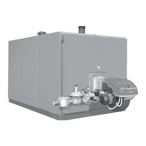
Product Description
Control Panels Control Panels
Recommended Burners
Product Identification
Technical Specifications
System Manager
Start up Pag
Temporary Shutdown
Preparing for Extended Periods of Disuse
Cleaning
Maintenance
Heating Engineer
Unpacking the Product Pag
Overall Dimensions and Weights
Handling
Place of Installation
Installation in Older Systems and Systems Requiring Modernisation
Water Connections
Anti-Condensate Pump
Combustion Gas Exhaust
Door Hinges
Fitting the Casing Panels
Technical Assistance Service
Preparing for Initial Start-Up Pag
Initial Start-Up
Checks During and after Initial Start-Up
Maintenance
Opening the Door
Adjusting the Door
Cleaning the Boiler
Troubleshooting
Advertisement
Quick Links
1
General Safety Information Pag
2
Product Description
3
Recommended Burners
4
Technical Specifications
Download this manual
S T E E L
B O I L E R S
RTQ
INSTALLATION, OPERATION, MAINTENANCE AND
SYSTEM MANAGEMENT MANUAL
Table of
Contents
Previous
Page
Next
Page
1
2
3
4
5
Advertisement
Table of Contents
Need help?
Do you have a question about the RTQ 109 and is the answer not in the manual?
Ask a question
Questions and answers
Related Manuals for Riello RTQ 109
Boiler Riello RTQ 953 Installation, Operation, Maintenance And System Management Manual
(28 pages)
Boiler Riello RTQ 91 3S Installation, Operation And Maintenance Manual
Steel boilers rtq 3s series (44 pages)
Boiler Riello RTQ 115 3S Installation, Operation And Maintenance Manual
Steel boilers rtq 3s series (44 pages)
Boiler Riello RTQ 1100 3S Installation, Operation And Maintenance Manual
Steel boilers rtq 3s series (44 pages)
Boiler Riello RTQ 1600 3S Installation, Operation And Maintenance Manual
Steel boilers rtq 3s series (44 pages)
Boiler Riello RTQ 91 Installation, Operation, Maintenance And Owner's Manual
Rtq series (32 pages)
Boiler Riello RTQ 715 Installation, Operation, Maintenance And Owner's Manual
Rtq series (32 pages)
Boiler Riello RTQ 3S Series Installation, Operation, Management And System Management Manual
Steel boilers (32 pages)
Boiler Riello RTQ 3S Series Installation, Operation, Maintenance And System Management Manual
Steel boilers (36 pages)
Boiler Riello RTC Series Installation, Operation And Service Manual
(52 pages)
Boiler Riello RTC Series Manual
(52 pages)
Boiler Riello RTS 3S Installation, Operation, Maintenance And System Management Manual
Steel boilers (40 pages)
Boiler Riello RTC-80 Series Installation, Operation And Service Manual
(56 pages)
Boiler Riello RTT Series Instructions For The Installer And For The Technical Assistance Centre
(20 pages)
Boiler Riello RTS 2S Seies Installation, Operation, Maintenance And System Management Manual
Steel boilers (36 pages)
Boiler Riello RTT 76 Instructions Manual
(20 pages)
This manual is also suitable for:
Rtq 154
Rtq 91
Rtq 235
Rtq 203
Rtq 297
Rtq 357
...
Show all
Rtq 418
Rtq 323
Rtq 467
Rtq 537
Rtq 597
Rtq 837
Rtq 715
Rtq 953
Rtq 1074
Rtq 1308
Rtq 1500
Rtq 1700
Rtq 2336
Rtq 2000
Table of Contents
Print
Rename the bookmark
Delete bookmark?
Delete from my manuals?
Login
Sign In
OR
Sign in with Facebook
Sign in with Google
Upload manual
Upload from disk
Upload from URL


Need help?
Do you have a question about the RTQ 109 and is the answer not in the manual?
Questions and answers