Table of Contents
Advertisement
Quick Links
Download this manual
See also:
User Manual
Advertisement
Chapters
Table of Contents

Related Manuals for Star Micronics LC-8521


Summary of Contents for Star Micronics LC-8521
- Page 1 DOT MATRIX PRINTER LC-8521 TECHNICAL MANUAL [ THIRD EDITION ]...
- Page 2 However, should any errors be detected, STAR would greatly appreciate being in- formed of them. • The above notwithstanding, STAR can assume no responsibility for any errors in this manual. © Copyright 1997 Star Micronics Co.,Ltd.
- Page 3 INTRODUCTION This manual describes the LC-8521 dot matrix printer. It is designed for use as a reference for periodic inspections and maintenance procedures to be executed by service personnel. It is not intended for the general user. Users of this manual should have a basic knowledge and understanding of the English language.
-
Page 5: Table Of Contents
CHAPTER 1 GENERAL SPECIFICATIONS General Spaecifications ..................3 External Appearance and Composition ..............5 Control Panel ......................7 3-1. Switch Combination Functions ................3-2. EDS Mode Settings ....................Parallel Interface....................10 4-1. General Specifications ..................4-2. Connector Signals ....................Serial Interface ..................... 11 5-1. - Page 6 – 2 –...
-
Page 7: General Specifications
General Specifications Printing System Serial Impact Dot-Matrix Printing Speed Pitch HS-Draft (cps/dpi) Draft (cps/dpi) LQ (cps/dpi) Pica (10 cpi) 400/80H 300/120H 100/360H Elite (12 cpi) 360/120H 120/360H Semi-condensed (15 cpi (S)) 450/120H 150/360H Semi-condensed (15 cpi (I)) 212/240H 150/360H Condensed pica (17 cpi) 242/240H 171/360H Condensed elite (20 cpi) - Page 8 Fanfold Paper width: 3″ to 16″ / 76 to 406mm Paper length 6″ / 152mm(min.) Paper weight (1-ply): 14 to 22 lbs / 52 to 82 g/m / 45 to 70 kg Multi-part: 11 to 14 lbs / 40 to 52 g/m / 34 to 45 kg;...
-
Page 9: External Appearance And Composition
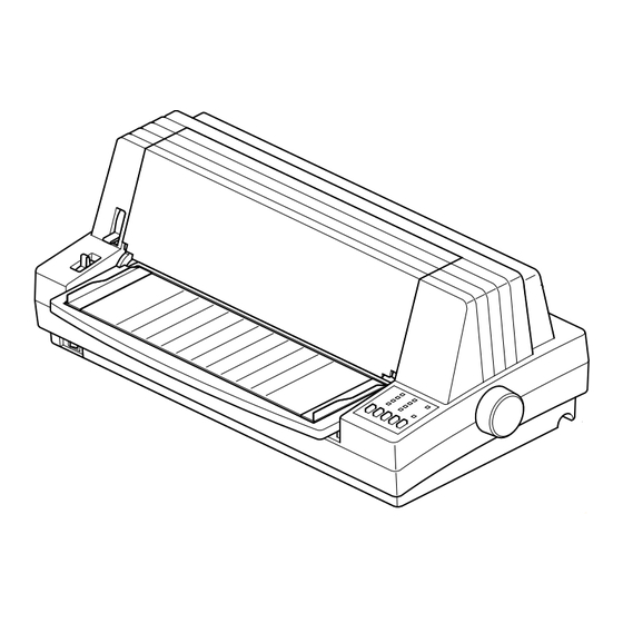
External Appearance and Composition Front cover Adjustment lever Release lever Paper guide Power switch Document table Platen knob Control panel Fig. 1-2 Front view of the Printer Parallel Interface connector Serial Interface connector Fig. 1-3 Rear view of the Printer –... - Page 10 Ribbon Cartridge Gap Adjustment assy Paper Feed Roller Print Head Platen Fig. 1-4 Front cover removed Tractor Carriage Paper Feed Motor Carriage Motor Ribbon Holder Printer Mechanism Power Supply Unit Main Logic Board Control Panel Board Fig. 1-5 Diagram of internal layout –...
-
Page 11: Control Panel
Control Panel 3-1. Switch Combination Functions POWER HS-DRAFT 10 CPI BANK DRAFT 12 CPI ROMAN 15 CPI SANSERIF COURIER COND PRESTIGE ORATOR PROP PARK PAPER ON LINE FONT PITCH SET/EJECT FEED BANK ON/OFF PRINT EXIT Font Selection Pitch Selection Set/Eject/Park Line Feed On-Line Panel Macro... -
Page 12: Eds Mode Settings
3-2. EDS Mode Settings (EDS - 1) Bank Switch Function Emulation *Standard / EPSON Character Table (CT) Standard / EPSON mode *Graphics Italics IBM mode IBM #2 IBM #1 RAM usage *Input Buffer Download Buffer Paper Out Detector *Enabled Disabled Multi-part mode * Auto selectable Normal mode... - Page 13 (EDS - 2) Bank Switch Function Data bits *8 bits 7 bits Parity check *Disabled Enabled Parity *Odd Even Protocol *DTR XON / XOFF (Not used) -------- -------- (Not used) -------- -------- Baud rate ----- 19200 *9600 4800 2400 1200 600 OFF ON OFF ON OFF ON...
-
Page 14: Parallel Interface
Parallel Interface 4-1. General Specifications Item Specifications Interface Centronics-compatible Synchronization System Via externally supplied STROBE pulse I/F Protocol Using ACK and BUSY signals Logic Level Compatible with TTL level 4µs 4µs Data STROBE (EDS B-6 : ON) STROBE (EDS B-6 : OFF) BUSY t : More than 0.5µs Fig. -
Page 15: Serial Interface
Serial Interface When using the serial interface, the optional Serial-Parallel Converter must be connected to the printer. 5-1. General Specifications Item Specifications Interface RS-232C level Synchronization System Asynchronous Baud rate 300 - 19,200 bits per second (BPS) [selectable] 300, 300, 600, 1200, 2400, 4800, 9600, 19200 BPS Word length Start bit: 1 bit... -
Page 16: Serial Interface - Spc-8K (Option)
Serial Interface - SPC-8K (Option) When using the serial interface, the optional Serial-Parallel Converter must be connected to the printer. 6-1. General Specifications Item Specifications Interface RS-232C level Synchronization System Asynchronous Baud rate 150 - 19,200 bits per second (BPS) [selectable] 150, 300, 600, 1200, 2400, 4800, 9600, 19200 BPS Word length Start bit:... -
Page 17: Dip Switch Settings
6-3. DIP Switch Settings Switch 8 data bits 7 data bits No parity Parity checked Handshaking protocols – see table below Odd parity Even parity Data transfer rate – see table below All switches are set to ON before the printer leaves the factory. Protocol Switch 3 Switch 4... -
Page 18: Ee-Prom Mode
EE-PROM mode 7-1. Outline These settings can be changed in the EE-PROM mode by writing data directly to the EE-PROM on the main logic board: Setting EE-PROM mode • Send <ESC><SUB>(09)H command. Canceling EE-PROM mode • Initialize the printer by sending <ESC>@ 7-2. -
Page 19: Ee-Prom Map
7-3. EE-PROM Map Address Function Factory data EDS setting Bit Function b0 Emulation STANDARD/EPSON Character Table b1 Standard / EPSON mode Graphics Italics IBM mode IBM #2 IBM #1 b2 RAM Usage Input Buffer Download Buffer b3 Paper out Detector Enabled Disabled Multi-part mode... - Page 20 EDS setting Bit Function b4 Eject direction for cut sheet Front Rear b5 Skew sensor for cut sheet Disabled Enabled EDS setting IBM Code Page (Character Table=Graphics, IBM#1, #2) Function b0 b1 b2 b3 b4 b5 Function b0 b1 b2 b3 b4 b5 #437 #869 #850...
- Page 21 Address Function Factory data EDS setting Baud rate Function Function 19200 1200 9600 4800 2400 Waiting Period for Paper loding Function Function 2.0sec 1.0sec 1.5sec 0.5sec EDS setting Function Top margin for Cut sheet 0″ Top margin for Fanfold paper (Pear) 0″...
- Page 22 Address Function Factory data Misalignment correction half-dot 120 DPI (H) Text Misalignment correction half-dot 120 DPI (H) Bit-image Misalignment correction half-dot ------------- Misalignment correction half-dot 180 DPI (H) Misalignment correction half-dot ------------- Misalignment correction half-dot ------------- Misalignment correction half-dot 240 DPI (H) Misalignment correction half-dot 360 DPI (H) Text...
-
Page 23: Rewriting The Ee-Prom
7-4. Rewriting the EE-PROM Follow this procedure to rewrite the EE-PROM. Turn the printer on. Load a BASIC disk in the computer. Turn the computer on. Set a sheet of paper in the printer, and press the ON LINE switch. Enter the program listed below and run the program. - Page 24 – 20 –...
- Page 25 CHAPTER 2 THEORY OF OPERATION Block Diagram ..................... 23 General Flow Chart (Main Logic Board) ............24 Power Supply Circuit ..................25 Mechanisms ......................26 4-1. Print Head Mechanism ..................4-1-1. Character Mechanism ..................4-1-2. Print Wire Drive Operation ................4-2. Print Head Carrying Mechanism ................. 4-3.
- Page 26 – 22 –...
-
Page 27: Block Diagram
Block Diagram The block diagram of this printer is shown in Fig. 2-1. Data (From Host Computer) Print head Parallel Carriage Driver interface motor Paper feed Gate array motor Switch Masked ROM Detectors Control panel board UVE-PROM EE-PROM Power supply unit Printer Main logic board mechanism... -
Page 28: General Flow Chart (Main Logic Board)
General Flow Chart (Main Logic Board) The flow chart below shows you the general flow of editing and printing operations. Fig. 2-2 General Flow Chart of Editing and Printing – 24 –... -
Page 29: Power Supply Circuit
Power Supply Circuit A ringing choke converter type circuit is used with a dropper type circuit in the power supply unit, fulfilling the input and output conditions described in the chart below. Voltage Range Max. Current Output Service Circuit Type 100 to 120VAC 2.5 A Input... -
Page 30: Mechanisms
Mechanism 4-1. Print Head Mechanism 4-1-1. Character Mechanism The wiring arrangement of the guide section on the print head styles is depicted in Fig. 2-4. Odd- and even-numbered wires are arranged it two columns. This is a result of the necessity for laying adjacent dots on top of one another. Fig. -
Page 31: Print Head Carrying Mechanism
4-2. Print Head Carrying Mechanism The print head carrying mechanism consists of a carriage, timing belt, carriage motor, and home position detector. Carriage The carriage is supported horizontally by the carriage stay and rear angle. The carriage moves from side to side with the print head mounted above it. -
Page 32: Ink Ribbon Feed Mechanism
4-3. Ink ribbon feed mechanism The ink ribbon feed mechanism is linked to the print head carrying mechanism so the ink ribbon always winds automatically in the same direction while the carriage moves left and right. The movement of the carriage along the serrated edge of the rear angle of the printer mechanism drives the idler gear. The rotation of the idler gear is conveyed sequentially to the gears that work and wind the ribbon. -
Page 33: Paper Feed Mechanism
4-4. Paper Feed Mechanism The turn of the paper feed motor is transmitted to the PF (Paper Feed) roller and tractor unit via the release lever, front- rear release arm, tractor clutch lever, clutch gear and change lever. The paper feed motor is a HB (Hy Brid) 4-phase and 96 pulse motor. -
Page 34: Detectors
4-5. Detectors Print head temperature detectors The A/D converter in the CPU detects the print head temperature at power on and before each line begins to print. FB11 Thermistor P90/AND Fig. 2-10 Printer head temperature detector circuit Control Method Temperature Temperature Print °... - Page 35 Paper end detector (Front) This detects the paper from the front of the printer. When paper is present, the photo transistor with the reflecting type photo sensor goes on. As soon as paper runs out, this transistor goes off, outputting a paper empty signal. Paper Fig.
- Page 36 Release lever position detector The leaf switch is open when the release lever is in the friction position, and is closed in the tractor position. Detecting signal Leaf switch Fig. 2-15 Release lever position detector Out put (V) Out put (V) Paper feeding Front SW Rear SW...
- Page 37 CHAPTER 3 ADJUSTMENTS This printer has undergone various adjustments so that it will attain a given standard of performance. In this chapter, a brief explanation is given of the methods for making adjustments. Follow the instructions when performing maintenance inspections or when replacing parts to correct malfunctions.
- Page 39 Adjustment of Gap Between Print Head and Platen Remove the upper case unit and ribbon holder [1] according to the procedures described in chapter 4. (Fig. 3-1) Install rear angle [2]. (Drive the screw tightly while pushing down rear angle.) Set adjust lever [3] to the second position from the bottom.
- Page 40 Adjustment of Timing Belt Tension Remove the front case unit according to the procedures described in chapter 4. Move the carriage unit [1] up to the extreme right position. Move the screw [3] fixing tension lever assembly [2] approximately 1mm to loosen the tension, then tighten the screw.
- Page 41 Adjustment of Paper end detector After replacing the paper-end detector, adjust the new detector as described here. First enter the dedicated command, then flow chart below.(Fanfold paper (Front) only) Dedicated command: <ESC> <SUB> (50)H n Send command Front Tractor ? Paper Park Enter paper-out value (A) Loading fanfold paper...
- Page 42 – 38 –...
- Page 43 CHAPTER 4 PARTS REPLACEMENT This chapter explains disassembly and reassembly of the printer. Note the following regarding disassembly and reassembly. Disconnect the printer from the wall outlet before servicing it. Assy is the reverse of disassembly unless otherwise specified. After reassembly, coat the screw heads with locking sealant. Lubrication information is not provided in this chapter.
-
Page 45: Upper Case Unit
Upper Case Unit Turn off the power switch. Remove the power cord from the AC output socket. Remove • Platen knob unit [1] • Rear cover [2] • Sheet guide unit [3] • Five screws [4] • Upper case unit [5] •... -
Page 46: Printer Mechanism
Printer Mechanism Remove Upper case unit as described in section 1. • Five screws [1] • Two screws [2] • Four connectors [3] • Head cable [4] • Printer mechanism [5] Main Logic Board Unit Remove Printer mechanism as described in section 3. •... -
Page 47: Power Supply Unit
Power Supply Unit Remove Printer mechanism as described in section 3. • Connector cable [1] • Seven screws [2] • Screw [3] • Inlet holder [4] • Switch holder [5] • Power supply unit [6] Fuse Remove Printer mechanism as described in section 3. •... -
Page 48: Carriage Motor Unit
Carriage Mottor Unit Remove Upper case unit as described in section 1. Loosen screw [1] Remove • Spring [2] Set tension lever assy [8] in the unlocked position • Four screws [3] • Four collars [4] • Timing belt [5] •... -
Page 49: Carriage Board Unit
Carriage Board unit Remove Printer head as described in section 8. • Connector [1] • Carriage board unit [2] Release the hook [3] Remove the head cables from the frame holder unit. Note : Fold the head cables according to the dimensions show below. 13.5 1 10 1 100 1... -
Page 50: Carriage Unit
10. Carriage Unit Remove Printer Mechanism as described in section 3. Carriage Motor Unit as described in section 7. • Stop ring [1] • Timing belt [2] • Two screws [3] • Rear angle assy [4] • Stop ring [6] •... -
Page 51: Frame Holder Unit
12. Frame Holder Unit Remove • Tractor unit [1] Carriage motor unit [2] as described in section 7. • Stop ring [3] • Four roll pins [4] • Three screws [5] • Fastener [6] • Detector unit [7] • Frame holder unit [8] Remove the head cable [9] frome Frame holder unit [8]. -
Page 52: Paper Guide Unit
14. Paper Guide Unit Remove Roller angle unit as described in section 11. • Paper feed roller unit as described in section 13. • Screw [1] • Detector cover [2] • Gear [3] • Seventeen screws [4] • Rom cover [5] •... -
Page 53: Paper Feed Motor Assy
16. Paper Feed Motor Assy Remove Paper guide unit as described in section 14. • Stop ring [1] • Two poly-sliders [2] • Spring [3] • Gear [4] • Paper feed motor assy [5] 17. Change Plate Assy Remove Paper guide unit as described in section 14. •... - Page 55 CHAPTER 5 MAINTENANCE AND LUBRICATION Maintenance ......................1-1. Cleaning ........................ 53 1-2. Checks ........................53 Lubrication ......................2-1. Lubricant ....................... 54 2-2. Lubricating Method ....................54 Lubricated Areas ....................54...
- Page 56 – 52 –...
- Page 57 Maintenance In order to maintain the optimum performance of this printer and to prevent trouble, maintenance must be carried out according to the following items. 1-1. Cleaning Removal of dirt Wipe off dirt with a soft cloth soaked in alcohol or benzine. Note: Do not use thinner, trichlene or ketone solvents because they may damage plastic parts.
- Page 58 Lubrication Lubrication is very important to maintain optimum performance and to prevent trouble. 2-1. Lubricant The type of lubricant greatly affects the performance and durability of the printer, especially in a low temperature environment. We recommend use of the grease and lubrication oils listed below for this printer Type of oil Product name Maker...
- Page 59 [10] [25] [25] Fig. 5-1 Lubricated Areas (printer mechanism) – 55 –...
- Page 60 [11] [12] [12] [13] [14] [13] [14] Fig. 5-2 Lubricated Areas (printer mechanism 2/2) – 56 –...
- Page 61 [15] [16] [15] Fig. 5-3 Lubricated Areas (Frame L) [17] [18] Areas to Lubricate Fig. 5-4 Lubricated Areas (Frame R) – 57 –...
- Page 62 [26] [26] [20] [20] [21] [22] [23] [19] Rear of Gear Cover Areas to Lubricate Fig. 5-5 Lubricated Areas (Carriage unit) [24] [24] [24] [24] Fig. 5-6 Lubricated Areas (Tractor unit) – 58 –...
- Page 63 CHAPTER 6 TROUBLESHOOTING Troubleshooting Procedures ................Unit Replacement Priority Chart ................ Repair by Unit Replacement................Repair by Parts Replacement ................4-1. Does not Operate at All with Power on............... 69 4-2. Power Supply Circuit Abnormal ................70 4-3. Defective Motor Operation ................... 71 4-4.
- Page 64 – 60 –...
-
Page 65: Troubleshooting Procedures
Troubleshooting Procedures Troubleshooting is never easy because various problems arise depending upon the particular location of the breakdown. The following procedures should be taken in making repairs. The first method is to make repairs through unit replacements. The two display codes appearing in the flow chart are defined as follows: 1) indicates main logic board replacement;... -
Page 66: Unit Replacement Priority Chart
Unit Replacement Priority Chart Unit Exchange Sequence Problem Category Remarks Power Main Printer Control Details supply unit logic board mechanism panel board Specific display lamp only will not glow Specific switch only cannot be input Buzzer does not sound (sound volume inadequate) Strange sounds... -
Page 67: Repair By Unit Replacement
Repair by Unit Replacement START • Turn power off. • Remove I/F cable. • Mount ink ribbon. • Set paper. • Move carriage to center. Turn power on. Carriage Moves? Carriage operates normally? *1 See (6) and waveform in item 5 of Chapter 6. Carriage motor operating waveform is normal? *1... - Page 68 On line lamp light? On line lamp signal is normal? Replace main logic board. Press on line switch to take off line. Replace control panel board. On line lamp is out? Press paper feed switch. Paper feed switch *2 See (7) waveform in operation is normal? item 5 of Chapter 6.
- Page 69 Printing operation *4 See (4) and (5) waveform in is normal? item 5 of Chapter 6. Print head drive signal waveform is normal? *4 1) Replace main logic board. 2) Replace printer mechanism. Replace printer mechanism. Paper feed *5 See (7) waveform in operation is item 5 of Chapter 6.
- Page 70 Printing begins? Printing operation normal? 1) Replace I/F cable. Stop print program. 2) Replace main logic board. 3) Check host computer. Carriage moves with hand? Replace printer mechanism. Output (+40V, +5V) of power supply unit is normal? *6 1) Replace main logic board. 2) Replace printer mecha- nism.
- Page 71 Output of power supply unit is normal? *7 Turn power off. Replace power supply unit. Connect connector CN3 from main logic board. Turn power on. Fuse blows out? Replace fuse. 1) Replace main logic board. 2) Replace printer mechanism. 3) Replace control panel board. *7 Power Supply Unit +40V ±...
- Page 72 *8 See (8) waveform in item 5 of Chapter 6. I/F signal is normal? *8 Ready condition? There is data transmission? Check hardware or host I/F mode set computer print program. up properly? 1) Replace I/F cable. 2) I/F cartridge 3) Replace main logic board.
-
Page 73: Repair By Parts Replacement
Repair by Parts Replacement 4-1. Does not Operate at All with Power on START +40V, +5V supplied? *9 See 4-2. Power Supply DC Power abnormal. Circuit Abnormal. RESET signal becomes HIGH? *10 Check RESET circuit; replace parts. Crystal waveform is normal? *11 Check crystal circuit;... -
Page 74: Power Supply Circuit Abnormal
4-2. Power Supply Circuit Abnormal Remove connector CN3 from main logic board. START Fuse F1 is blown? Replace Fuse F1 Fuse is blown again? Replace 1) Power supply unit The no load voltages are below: +40V ± 5% +40V Line Between Pin 5 and Pin 3 of CN1 +5V ±... -
Page 75: Defective Motor Operation
4-3. Defective Motor Operation Paper Feed Motor Carriage Motor START START CR-ø1, LF-ø1, ø2, ø3, ø4 are ø2, ø3, ø4 are normal? *13 normal? *12 Check and replace Check and replace 1) TA 8 1) TA7 2) Gate array 2) Gate array Replace Replace LF motor... -
Page 76: Defective Print Head Operation
4-4. Defective Print Head Operation START Does not print at all? A specific pin does not +40V line work? Check and replace is supplied? • TA1 (HD1, 2, 3, 4) • TA2 (HD5, 6, 7, 8) • TA3 (HD9, 10, 11, 12) •... -
Page 77: Defective Interface Operation
4-5. Defective Interface Operation START Press on line switch to take on line. Send print program from host computer. *15 See (8) waveform in item 5 of Chapter 6. Is I/F signal normal? *15 Incorrect print generated? Check I/F cable. Check and replace 1) IC 3 2) Gate array... -
Page 78: Waveform With Oscilloscope
Waveform with Oscilloscope (1) Crystal (12 MHz) (2) RESET (Power on reset) (4V) (2V) (0V) (0V) (4V) (0V) Crystal Pin 28 of IC7 Upper : RESET input Pin 1 of IC5 Time/Div : 0.2 µs Lower : RESET output Pin 3 of IC5 Volt/Div : 1V Time/Div : 10 ms... - Page 79 (7) Paper Feed Motor Control Signal and (8) Parallel Interface (parallel type Only) Driving Signal (5V) (5V) (0V) (0V) (100V) (4V) (0V) (0V) Upper : LF-ø1 Control Signal Pin 40 of IC4 Upper : STB Pin 1 of CN1 Lower : LF-ø1 Driving Signal Pin 1 of CN9 Lower : BUSY Pin 11 of CN1 Time/Div : 2 ms...
- Page 80 – 76 –...
- Page 81 CHAPTER 7 PARTS LIST HOW TO USE PARTS LIST DRWG. NO. This column shows the drawing number of the illustration. REVISED EDITION MARK This column shows a revision number. Part that have been added in the revised edition are indicated with "#". Part that have been abolished in the revised edition are indicated with "*".
-
Page 82: Printer Assembly
Printer Assembly 1-1. Disassembly Drawing 10 16 – 78 –... -
Page 83: Parts List
1-2. Parts List Printer Assembly DRWG.NO. REV. PARTS NO. PARTS NAME Q’TY REMARKS RANK 89430300 MECHANISM WITH HEAD DP695 87816300 PLATEN KNOB UNIT QBF-10(D) 86823180 POWER SUPPLY UNIT HBF-15 86822140 MAIN LOGIC BD UNIT HBF-15 EXCEPT FOR RU 86822310 MAIN LOGIC BD UNIT HBF-15 RU FOR RU 86821090 LOWER CASE UNIT... -
Page 84: Printer Mechanism
Printer Mechanism 2-1. Disassembly Drawing 10-3 10-1 10-2 12-2 12-1 13-2 13-3 13-1 – 80 –... - Page 85 – 81 –...
-
Page 86: Parts List
2-2. Parts List Printer Mechanism DRWG.NO. REV. PARTS NO. PARTS NAME Q’TY REMARKS RANK 89163010 PRINT HEAD DP690 86437030 TENSION LEVER UNIT 86437310 TENSION LEVER ASSY 83200222 PULLEY CAP 83120760 TIMING PULLEY B 04020015 STOP RING SE3.0 03870405 BEARING L-940ZZR 86432030 CARRIAGE UNIT 86432031 CARRIAGE UNIT 86430750 GAP ADJUSTMENT ASSY... - Page 87 Printer Mechanism DRWG.NO. REV. PARTS NO. PARTS NAME Q’TY REMARKS RANK 80531210 GROUND SPRING B 80531200 GROUND SPRING A 80531201 GROUND SPRING A 80521290 SPRING C120-060-0060G 80511270 SPRING E058-080-0180 80511050 SPRING E050-045-0164 80510960 SPRING E050-040-0144 80510890 SPRING E060-050-0221 80201280 PAPER FEED ROLLER UNIT 80201281 PAPER FEED ROLLER UNIT FASTENER T18S 04020018 STOP RING SE8.0...
-
Page 88: Sub - Assembly
Sub - Assembly 3-1. Lower Cace Unit 5-10 DRWG.NO. REV. PARTS NO. PARTS NAME Q’TY REMARKS RANK 83026491 LOWER CASE HBF-15 83026492 LOWER CASE HBF-15 82501530 GROUND SPRING HBF-15 POWER CHASSIS HBF-15 LOWER CASE CHASSIS HBF-15 SHEET 280X37X10 SHEET F HBF-15 80995470 RUBBER FOOT 20X20 HBF-15... -
Page 89: Sheet Guide Unit
3-2. Sheet Guide Unit DRWG.NO. REV. PARTS NO. PARTS NAME Q’TY REMARKS RANK 83904920 GUIDE HINGE ARM HBF-15 83904910 SLIDER HBF-15 83904830 ADJUSTER L HBF-15 83904820 ADJUSTER R HBF-15 83904811 SHEET GUIDE HBF-15 83904812 SHEET GUIDE HBF-15 83026610 ADJUSTER GUIDE HBF-15 83026611 ADJUSTER GUIDE HBF-15... -
Page 90: Printer Cover Unit
3-3. Printer Cover Unit DRWG.NO. REV. PARTS NO. PARTS NAME Q’TY REMARKS RANK 83026520 COVER WINDOW HBF-15 83026510 PRINTER COVER HBF-15 FRONT GUIDE SUPPORTER JBA-15H 80060440 BRAND PLATE HBF-15 01903038 SCREW TAT 3-10 PT-FL – 86 –... -
Page 91: Upper Case Unit
3-4. Upper Case Unit 8-10 8-1-1 8-1-3 8-11 8-1-2 8-1-3 DRWG.NO. REV. PARTS NO. PARTS NAME Q’TY REMARKS RANK 86820720 REAR CASE ASSY HBF-15 8-1-1 REAR CASE HBF-15 8-1-2 SHEET G HBF-15 8-1-3 SHEET C HBF-15 83026482 UPPER CASE HBF-15 83026483 UPPER CASE HBF-15 RUBBER CUSHION B... -
Page 92: Tractor Unit
3-5. Tractor Unit 9-10 9-10 9-1-2 9-1-4 9-1-1 9-10 9-1-3 DRWG.NO. REV. PARTS NO. PARTS NAME Q’TY REMARKS RANK 86436340 TRACTOR SHAFT ASSY 9-1-1 83101690 TRACTOR GEAR 9-1-2 TRACTOR SHAFT 9-1-3 04020017 STOP RING SE5.0 9-1-4 04012002 ROLL PIN SP2.0X10 SHEET GUIDE 83401450 TRACTOR LEVER L 83401440 TRACTOR LEVER R... -
Page 93: Serial-Parallel Converter (Option)
3-6. Serial - Parallel Converter (Option) 23-1 23-7 23-5 23-2 23-3 23-8 23-4 23-6 23-6 23-6 DRWG.NO. REV. PARTS NO. PARTS NAME Q’TY REMARKS RANK 23-1 UPPER CASE SPC-8K 23-2 CPU BOARD UNIT SPC-8K 23-3 87590020 IF BOARD UNIT SPC-8K 23-4 LOWER CASE UNIT SPC-8K... -
Page 94: Carriage Unit
3-7. Carriage Unit 3-3-8 3-11 3-3-7 3-3-1 3-12 3-3-6 3-1-1 3-3-3 3-14 3-3-5 3-3-4 3-3-2 3-14 3-10 3-4-1 3-2-4 3-2-2 3-2-1 3-13 3-2-3 DRWG.NO. REV. PARTS NO. PARTS NAME Q’TY REMARKS RANK 86432380 CARRIAGE ASSY 3-1-1 82501520 HEAD GROUND SPRING 86432360 CARD HOLDER UNIT 3-2-1 86432630 PAPER DETECTOR BOARD UNIT 695... -
Page 95: Platen Assy
3-8. Platen Assy DRWG.NO. REV. PARTS NO. PARTS NAME Q’TY REMARKS RANK 83201080 BUSHING F10X14X5.5 701C 80202320 PLATEN 04020018 STOP RING SE8.0 04012503 ROLL PIN SP2.5X14 – 91 –... -
Page 96: Roller Angle Assy
3-9. Roller Angle Assy 9-1-1 DRWG.NO. REV. PARTS NO. PARTS NAME Q’TY REMARKS RANK 86430680 PF ROLLER SHAFT F ASSY 9-1-1 83201130 PAPER FEED ROLLER 83201140 BUSHING F7X10X6 83101880 GEAR 15X1 701C ROLLER ANGLE 80531250 PF ROLLER SPRING 80531251 PF ROLLER SPRING 80520520 SPRING C090-070-0150 04020017 STOP RING SE5.0 02307050 POLY-SLIDER WP7X0.5... -
Page 97: Frame Holder Unit
3-10. Frame Holder Unit 11-3 11-4 11-2 11-1 DRWG.NO. REV. PARTS NO. PARTS NAME Q’TY REMARKS RANK 11-1 86031030 RUBBER BUSHING B UNIT 11-2 82501510 RELEASE SPRING 11-3 82040710 FRAME HOLDER 82040711 FRAME HOLDER 11-4 00630404 SCREW TR 3-4 – 93 –... -
Page 98: Paper Guide Unit
3-11. Paper Guide Unit 14-4 14-1 14-2 14-4 14-4 14-3 DRWG.NO. REV. PARTS NO. PARTS NAME Q’TY REMARKS RANK 14-1 86430480 PAPER GUIDE C ASSY 14-2 82040730 PAPER GUIDE B 14-3 82040720 PAPER GUIDE A 14-4 04011501 ROLL PIN SP1.5X6 –... -
Page 99: Frame L Unit
3-12. Frame L Unit 16-1-1 16-1-2 16-13 16-5 16-13 16-1 16-11 16-13 16-11 16-12 16-3 16-10 16-8 16-12 16-11 16-6 16-4 16-2 16-7 16-9 DRWG.NO. REV. PARTS NO. PARTS NAME Q’TY REMARKS RANK 16-1 86430640 DETECTOR UNIT B 16-1-1 86430660 PE BOARD ASSY 16-1-2 09090039 LEAF SWITCH LSA1119H 16-2... -
Page 100: Frame R Unit
3-13. Frame R Unit 17-1 17-3 17-4 17-10 17-9 17-9 17-5 17-8 17-10 17-6 17-7 17-2 DRWG.NO. REV. PARTS NO. PARTS NAME Q’TY REMARKS RANK 17-1 86430510 PF MOTOR ASSY 17-2 FRAME R ASSY 17-3 83401470 TRACTOR CLUTCH LEVER R 17-4 83101940 CLUTCH GEAR 17-5... - Page 101 [Blank Page] – 97 –...
-
Page 102: Wiring Scheme Of Printer
Wiring Scheme of Printer – 98 –... - Page 103 – 99 –...
-
Page 104: Electrical Parts
Electrical Parts 5-1. Main Logic Board 5-1-1. Circuit Diagram – 100 –... - Page 105 – 101 –...
- Page 106 – 102 –...
- Page 107 [Blank Page] – 103 –...
-
Page 108: Component Layout
5-1-2. Component Layout – 104 –... - Page 109 – 105 –...
-
Page 110: Parts List
5-1-3. Parts List Main Logic Board DRWG.NO. REV. PARTS NO. PARTS NAME Q’TY REMARKS RANK 08200164 IC-I/F SP232ACP NOT USED 08210006 TTL IC 7406 08240087 GATE ARRAY LZ9G11K-F24W1 08200142 IC-RESET PST592D-2* 08220092 IC-LIN UPC339C 08250021 CPU TMP95C061BEF 08222047 EEPROM KM93C46 08210094 TTL IC 74LS07 IC10 08222017 EPROM... - Page 111 Main Logic Board DRWG.NO. REV. PARTS NO. PARTS NAME Q’TY REMARKS RANK NOT MOUNTED CERA. CAPA. 33PF C19-20 NOT USED NOT MOUNTED C22-23 CERA. CAPA. 4700PF C24-25 CERA. CAPA. 470PF C26-29 CERA. CAPA. 0.01UF CERA. CAPA. 0.022UF 50V CERA. CAPA. 470PF CERA.
- Page 112 Main Logic Board DRWG.NO. REV. PARTS NO. PARTS NAME Q’TY REMARKS RANK R45-46 RD RESISTOR 10 K-OHM 1/6W RN RESISTOR 5.1 K-OHM 1/6W RN RESISTOR 2.2 K-OHM 1/6W R49-50 RD RESISTOR 4.7 K-OHM 1/6W R51-52 RD RESISTOR 10 K-OHM 1/6W R53-54 RN RESISTOR 1.0 OHM 3W RD RESISTOR 1 K-OHM 1/6W...
- Page 113 Main Logic Board DRWG.NO. REV. PARTS NO. PARTS NAME Q’TY REMARKS RANK R144-145 RN RESISTOR 1.0 OHM 3W R146-147 RD RESISTOR 4.7 K-OHM 1/6W R148-149 RD RESISTOR 10 K-OHM 1/6W RESIS. ARRAY 4.7K-OHM 1/8W 8EL RESIS. ARRAY 1.8K-OHM 1/8W 8EL RESIS.
-
Page 114: Control Panel Board
5-2. Control Panel Board 5-2-1. Circuit Diagram 5-2-2. Component Layout 5-2-3. Parts List Control Panel Board DRWG.NO. REV. PARTS NO. PARTS NAME Q’TY REMARKS RANK LED1-10 08300151 LED LTL232 08300168 LED GL3EG8 SW1-5 09010041 PUSH SWITCH SKHHAL 09010061 PUSH SWITCH EVQ PAE 04M CN12 09100624 CONNECTOR 51048-1300 –... -
Page 115: Connected Board
5-3. Connected Board 5-3-1. Circuit Diagram 5-3-2. Component Layout 5-3-3. Parts List Relay Board DRWG.NO. REV. PARTS NO. PARTS NAME Q’TY REMARKS RANK CN10A 09100637 CONNECTOR 51048-1700 CN10B 09100688 CONNECTOR 51048-1600 CN11A-B 09100419 CONNECTOR HLEM19S-1 – 111 –... -
Page 116: Power Supply Unit
5-4. Power Supply Unit 5-4-1. Circuit Diagram – 112 –... -
Page 117: Component Layout
5-4-2. Component Layout – 113 –... -
Page 118: Parts List
5-4-3. Parts List Power Supply Unit DRWG.NO. REV. PARTS NO. PARTS NAME Q’TY REMARKS RANK IC-REG FA5304AP IC-REG PQ05RF11 IC-REG MK1210 FAST DIODE RU1P FAST DIODE ERA92-02*A DIODE 1S954 SCHOTTKY DIODE SB140 FAST DIODE 5FL2CZ47A DIODE RL1N4007*A DIODE DS446 DIODE STACK D3SBA60 BEADS INDUCTOR B-01AT BEADS INDUCTOR RH035047AT-Y7 BEADS INDUCTOR B01-RT... - Page 119 Power Supply Unit DRWG.NO. REV. PARTS NO. PARTS NAME Q’TY REMARKS RANK RN RESISTOR 100 OHM 3W RN RESISTOR 0.15 OHM 2W RD RESISTOR 100 OHM 1/4W RD RESISTOR 10 OHM 1/4W RD RESISTOR 680 K-OHM 1/4W RD RESISTOR 330 OHM 1/4W RD RESISTOR 1 K-OHM 1/4W RD RESISTOR 560 OHM 1/4W RD RESISTOR 2.2 K-OHM 1/6W...
-
Page 120: Serial - Parallel Converter Board ( Option )
Serial - Parallel Converter Board ( Option ) 6-1. Wiring Scheme – 116 –... -
Page 121: I/F Board
6-2. I/F Board 6-2-1. Circuit diagram 6-2-2. Component Layout 6-2-3. Parts List DRWG.NO. REV. PARTS NO. PARTS NAME Q’TY REMARKS RANK IC101 08200125 IC-I/F LT1081CN IC102 08200109 IC-RESET M51953BL R101 RD RESISTOR 3.3 K-OHM 1/6W C101-104 CHEM. CAPA. 4.7UF C105 CAPACITOR 0.1UF 50V CN101 09100461 CONNECTOR DBLC-J25SAF-23L8... -
Page 122: Cpu Board
6-3. CPU Board 6-3-1. Circuit diagram – 118 –... -
Page 123: Component Layout
6-3-2. Component Layout 6-3-3. Parts List CPU Board DRWG.NO. REV. PARTS NO. PARTS NAME Q’TY REMARKS RANK 08250011 MASKED CPU HD63B01YF-IF 08221021 SRAM HM6264LFP-100NS 07603007 DIGITAL TRANSISTOR RTIN434C-T TR2-4 06751021 CHIP RESISTOR 1 K-OHM 1/10W 06754721 CHIP RESISTOR 4.7 K-OHM 1/10W TR6-7 06783313 CHIP RESISTOR 330 OHM 1/8W 06754721 CHIP RESISTOR 4.7 K-OHM 1/10W... - Page 124 Worldwide Headquarters STAR MICRONICS ASIA LTD. STAR MICRONICS CO., LTD. Rm 1802-6,18/F., Tower II, Enterprise Square 9 Sheung Yuet Road, Kowloon 536 Nanatsushinya, Shimizu, Bay Hong Kong Shizuoka, 424-0066, Japan Tel: 852-2796-2727 Telefax: 852-2799-9344 Tel: 0543-47-0113 Telefax: 0543-48-5013 Distributed by Printed in Japan –...
Need help?
Do you have a question about the LC-8521 and is the answer not in the manual?
Questions and answers