
Related Manuals for MTE HYDROCAL 1001 Plus

Summary of Contents for MTE HYDROCAL 1001 Plus
- Page 1 HYDROCAL 1001+ Composite Gas-in-Oil Sensor with Moisture in Oil Measurement Installation and operation manual HYDROCAL 1001+ Installation and operation manual Edition RS485 01.2015...
- Page 2 D-21438 Brackel Germany Phone: +49-4185-5857-0 Fax: +49-4185-5857-68 Email: info@emh.de Copyright MTE Meter Test Equipment AG All rights reserved. The contents of this manual are subject to change without notice. All efforts have been made to ensure the accuracy of this publication but...
-
Page 3: Table Of Contents
Table of Content General............................. 3 Installation instructions ......................4 2.1. Installation positions ......................4 2.2. Safety precautions ........................ 5 2.3. Installation preparation ......................7 2.3.1. Mechanical connection ....................7 2.3.1.1. Flange connection ....................7 2.3.1.2. Fitting with union nut ....................7 2.3.2. - Page 4 4.3.1.6. LED bar level - Gas ............ 34 4.3.1.7. LED bar levels - Moisture ........... 46 4.3.2. Special Operation ......................47 4.3.2.1. Unit Power-On - Boot ................... 47 4.3.2.2. Update of Firmware - Downloader ................ 48 4.3.2.3. Update of Firmware - via TFTP ................50 4.3.2.4.
-
Page 5: General
General The HYDROCAL 1001+ is a permanently installed composite gas-in-oil sensor for the analysis of moisture in oil and the following dissolved key fault gases (TDCG = Total Dissolved Combustible Gases): Fault gas TDCG contribution Hydrogen (H approx. 20 % Carbon Monoxide (CO) approx. -
Page 6: Installation Instructions
Installation instructions 2.1. Installation positions To ensure the correct function of a HYDROCAL unit the installation position is very important. On a typical transformer three positions are possible: Pos. 1 Output side of cooling unit: Please install the unit on a straight piece of pipe on the cooler output between the cooler and the main oil tank. -
Page 7: Safety Precautions
2.2. Safety precautions The following security precautions must be strictly observed during the installation. Otherwise no war- ranty claims will be accepted. Never remove the protection cap from the connection thread until you are ready to mount the unit on the transformer valve. The protection cap protects the connection unit against dust and from other impurities. - Page 8 Remove the HYDROCAL unit from the valve every time you degas or refill the transformer. You can also close the transformer valve. Never operate the HYDROCAL unit on a valve that is closed for a long period of time. Remove the unit if this cannot be avoided. Please refer to the de-installation instructions.
-
Page 9: Installation Preparation
2.3. Installation preparation Attention!!! Always open the aeration screw first!!! Before installation, a visual inspection of the membrane must be carried out. Open the aeration screw 3 to 4 turns while turning CCW with a long Allen key No. 4. Slowly remove the protection cap while turning CCW and check the membrane. -
Page 10: Auxiliary Supply Connection
2.3.2. Auxiliary supply connection The HYDROCAL unit is available in 4 different voltage versions (must be specified when ordering). Depending on the used nominal voltage version there must be an AC or DC power supply with a 3 pin power cable (2.4.2) close to the HYDROCAL unit: Nominal voltage version HYDROCAL Auxiliary supply voltage 120 V -20% +15% AC 50/60Hz... -
Page 11: Thread Sealant
2.3.4.2. Thread sealant ® As a thread sealant we recommend the two Henkel products LOCTITE 7471 (activate) and ® ® LOCTITE 577 (seal and fix) in combination. The activator LOCTITE 7471 is used to increase the ® rate of cure and is applied before the actual thread adhesive LOCTITE 577 is applied on 3 to 4 turns of the external thread of the HYDROCAL connection unit. -
Page 12: Installation
2.4. Installation After the installation preparation is completed, the HYDROCAL unit can be installed. The installation is divided into 3 steps: Mechanical installation (2.4.1) Electrical connection (2.4.2) Putting into operation (2.4.3) 2.4.1. Mechanical installation The sequence of the mechanical installation depends on which connection type is available on the transformer side. -
Page 13: Direct Installation
2.4.1.1. Direct installation Direct installation means, the unit is screwed directly onto the threaded flange, i.e. the unit is rotated around its own axis in order to fix it. In this type of installation the space around the center of the connection unit must be free in a diameter of 280 mm. -
Page 14: Indirect Installation
Now align the unit clockwise until the position of the aeration screw is at 12 o`clock. Make sure that the unit is tight in this position. Note: The alignment of the unit must be only clockwise. Once the unit is turned counterclockwise during the alignment, the installation procedure must be performed once again! Risk of oil leak- age! Attention !!! - Page 15 Tighten the union nut with a tin spanner M55 or an adjustable tin spanner 1 ½“, while you hold the HYDROCAL unit in position using a tin spanner M55 or an adjustable tin spanner 1 ½“. Make sure that the alignment of the HYDROCAL unit is still correct afterwards. Attention !!! The following steps must be done according to the company procedures.
-
Page 16: Electrical Connection
2.4.2. Electrical connection Use protective conduits as protection for all cables and connect them to the corresponding connectors inside of the unit (3.3). All cables have to be provided by the customer. For feed through, following cable gland must be used for all cables: 1x M20 SKINTOP cable gland (Clamping range 7,0 ... -
Page 17: Putting Into Operation
Communication connection: The Ethernet communication is either connected via copper wire (RJ45) or fibre optical (SC Du- plex) (must be specified when ordering). Copper wire: Recommendation for Ethernet communication cable (copper): Cable type: Ethernet cable Cat. 5e with RJ45 connector Cable diameter : 6,3 mm Fibre optical:... -
Page 18: Hardware Components
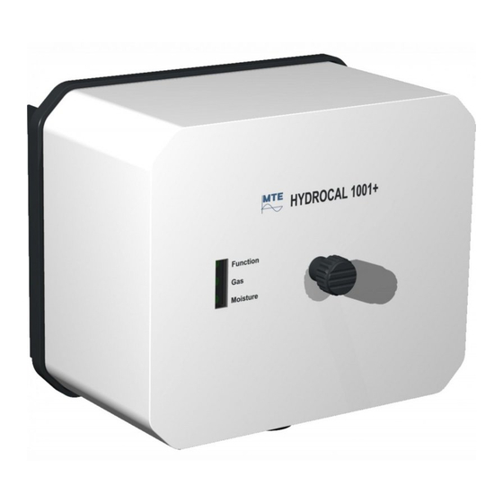
Hardware components 3.1. Front view The front consists of the following components: Protection cover with aeration hole Knurled thumb screw to fasten the protection cover Function LED of external user interface Gas LED of external user interface Moisture LED of external user interface HYDROCAL 1001+ Installation and operation manual Page 16/76... -
Page 19: Rear View
3.2. Rear view Oil unit with connection thread G 1½” DIN ISO 228-1 1½” NPT ANSI B 1.20.1 HYDROCAL 1001+ Installation and operation manual Page 17/76... - Page 20 Supply voltage connection with SKINTOP® cable gland M20 Nominal voltages: 120 V -20% +15% AC 50/60Hz 230 V -20% +15% AC 50/60Hz 120 V -20% +15% DC 230 V -20% +15% DC Other nominal voltages on request! Power consumption: max. 250 VA Micro-fuse at 120V: T3.15A Micro-fuse at 230V: T2A Connect the supply voltage cable as followed:...
-
Page 21: Connections Of Measurement- And Controller Card
3.3. Connections of measurement- and controller card Reset Button [→0] (to zero) Functional test and alarm acknowledgment (automatic test of LEDs and digital outputs) Communication interface reset – in conjunction with the test button Test Button [Test] Test mode (detailed manual test of analog- and digital outputs) Communication interface reset –... - Page 22 Function, Gas & Moisture LEDs of external user interface with 3 multicolor LEDs [10] Connection ETHERNET communication Communication connection via Ethernet Copper wired Fibre optic (RJ45) (SC-Duplex) The connection sockets are mounted directly on the measurement- and controller card (must be specified when ordering). Jumper J1 –...
- Page 23 [11] Connection terminal X1: RS485 / analog outputs Connection for RS485 interface / analog outputs DC (0/4…. 20 mA DC) OUT RS485 interface X1:1 OUT RS485 interface X1:2 GND RS485 interface X1:3 AO1 ...
-
Page 24: Beeper
3.3.1. Beeper The measurement- and controller card contains a beeper for additional acoustic signalization. The beeper has three different beep sounds which vary in lengths and sound form: Icon Description Short constant beep Long constant beep with a slightly higher tone pitch Long oscillating beep (whistle sound) HYDROCAL 1001+ Installation and operation manual Page 22/76... -
Page 25: Connections Of Power Supply Card
3.4. Connections of power supply card Connection terminal X1: Supply voltage / heating resistor X1:1 Protecting earth (PE) - Green - yellow X1:2 - (not connected) X1:3 Neutral (N) - Blue X1:4 - (not connected) Phase (L) –... -
Page 26: Wiring Of The Heating Resistors
3.5. Wiring of the heating resistors The HYDROCAL 1001+ unit is available in four supply voltage versions (must be specified when or- dering). The solid-state relay varies between supply voltage type (AC and DC): For AC supply voltages the solid-state relay crydom D2410 AC 10 A is used (left). ... -
Page 27: Wiring Heating Resistors For 230 V
3.5.1. Wiring heating resistors for 230 V Note: The solid-sate relay must correspond to the supply voltage type (AC or DC)!!! HYDROCAL 1001+ Installation and operation manual Page 25/76... -
Page 28: Wiring Heating Resistors For 120 V
3.5.2. Wiring heating resistors for 120 V Note: The solid-sate relay must correspond to the supply voltage type (AC or DC)!!! HYDROCAL 1001+ Installation and operation manual Page 26/76... -
Page 29: Firmware
Firmware 4.1. General information The composite Gas-in-Oil sensor with moisture in oil measurement HYDROCAL 1001+ is based on a microprocessor controlled measurement system. A 32 Bit „Coldfire“ processor with a clock frequency of 240 MHz is used. The system has a FLASH memory of 32 Mbyte for permanent storing of the measurement data, which offers a storage capacity of 2 years. -
Page 30: Function Led
4.2.1. Function LED The HYDROCAL unit contains an internal system monitoring which is assigned to the function LED and relay output 4 (connection terminal X2:7&8). The following internal error sources are monitored: Loss of time Data memory not ready ... - Page 31 concentration Icon Color sequence HYDROCAL 1001+ Installation and operation manual Page 29/76...
-
Page 32: Moisture Led
Note: The standard settings for gas concentration absolute alarm (High-High) are: Level 1: 500 Level 2: 1000 Delay 1 [s]: 7200 or 2:00:00 Delay 2 [s]: 43200 or 12:00:00 Action 1: Output,Hold Action 2: Output,Hold Note: The standard settings for gas concentration daily trend alarm (High-High) are: ... -
Page 33: Internal User Interface
4.3. Internal user interface The internal user interface consists of 15 single color light-emitting diodes (LEDs) to reflect the sys- tem status and two push buttons to allow the activation of special functions. Under normal conditions the LEDs reflect the status of the communication interfaces, analog outputs and gas concentration (absolute, daily- and weekly trend) and moisture concentration: During special operations the LEDs are used in another manner to reflect the status or progress of the related task. -
Page 34: Normal Operation
4.3.1. Normal Operation Normal operation is the default status and is automatically invoked when the unit starts up. 4.3.1.1. LED & energy save mode As the HYDROCAL 1001+ unit is operating behind a non-transparent protection cover most of the time the LEDs of the internal user interface are switched off to save energy and release load from the power supply. -
Page 35: Led Gas Analog Output
4.3.1.4. LED Gas analog output The status and the actual value of the analog output are represented by a red- and a green single color LED. The LEDs illustrates the status and the actual value of the analog output as follow: Description Analog output not configured Red LED... - Page 36 4.3.1.6. LED bar level - Gas The HYDROCAL unit contains an additional LED bar level monitoring to give the user a rough over- view of the absolute gas concentration, gas concentration daily trend and gas concentration weekly trend. It is completely independent form the alarm level monitoring and is visualized with 1 green- and 3 red single color LEDs.
- Page 37 Color sequence – LED bar level concentration HYDROCAL 1001+ Installation and operation manual Page 35/76...
- Page 38 Color sequence – LED bar level concentration HYDROCAL 1001+ Installation and operation manual Page 36/76...
- Page 39 Color sequence – LED bar level concentration HYDROCAL 1001+ Installation and operation manual Page 37/76...
- Page 40 Color sequence – LED bar level concentration HYDROCAL 1001+ Installation and operation manual Page 38/76...
- Page 41 Color sequence – LED bar level concentration HYDROCAL 1001+ Installation and operation manual Page 39/76...
- Page 42 Color sequence – LED bar level concentration HYDROCAL 1001+ Installation and operation manual Page 40/76...
- Page 43 Color sequence – LED bar level concentration HYDROCAL 1001+ Installation and operation manual Page 41/76...
- Page 44 Color sequence – LED bar level concentration HYDROCAL 1001+ Installation and operation manual Page 42/76...
- Page 45 Color sequence – LED bar level concentration HYDROCAL 1001+ Installation and operation manual Page 43/76...
- Page 46 Color sequence – LED bar level concentration HYDROCAL 1001+ Installation and operation manual Page 44/76...
- Page 47 Color sequence – LED bar level concentration Note: The standard settings for LED bar level gas concentration absolute are: Level 1: 100 Level 2: 500 Level 3: 1000 Note: The standard settings for LED bar level gas concentration daily trend are: ...
-
Page 48: Led Bar Levels - Moisture
4.3.1.7. LED bar levels - Moisture The HYDROCAL unit contains an additional LED bar level monitoring to give the user a rough over- view of the moisture concentration. It is completely independent form the alarm level monitoring and is visualized with 1 green- and 2 red single color LEDs. The moisture concentration has 2 configura- ble levels (level 1 ... -
Page 49: Special Operation
4.3.2. Special Operation During special operations the LEDs are used to reflect the status or progress of the corresponding task. Following special operations are available on the unit: Unit Power-On - Boot (4.3.2.1) Update of Firmware - Downloader (4.3.2.2) ... -
Page 50: Update Of Firmware - Downloader
4.3.2.2. Update of Firmware - Downloader Once a firmware download operation is started during the boot sequence, the unit switches to a spe- cial mode - the so called downloader. This status can be recognized by the following special LED pattern (2 red LEDs are turned on and 1 green LED is circulating counter clockwise): ... - Page 51 The next steps are erasing the EEPROM (optional), writing and verifying the new firmware. Each step brings up one additional red LED with the green LEDs being used as a progress bar (restarted in each operation). If an error occurs all LEDs are turned off and the downloader restarts in the boot timeout sequence. ...
-
Page 52: Update Of Firmware - Via Tftp
4.3.2.3. Update of Firmware - via TFTP A firmware update can also occur in the running firmware using the Ethernet interface and the so called TFTP protocol. The transfer of the firmware image data occur in the background and is not visualized. -
Page 53: Functional Test
4.3.2.4. Functional Test The functional test is quick unit test which execute an automatic sequence with following order: LEDs of internal user interface LEDs of external user interface and digital relay output LEDs of internal- and external user interface ... - Page 54 II - LEDs of internal user interface and digital relay outputs h’ with Jumper J1 on Pos. 1 (J1:1-2) Relay output 4 (X2:7/8) h’’ with Jumper J1 on Pos. 2 (J1:2-3) Relay output 4 (X2:7/8) ...
-
Page 55: Test Mode
4.3.2.5. Test Mode The test mode grants a more detailed test of the HYDROCAL unit outputs. The analog- and digital outputs along with the corresponding LEDs can be verified. The test points are available in following order: Test Gas concentration Analog output 1 X1:4/5 ... - Page 56 I - Test Gas concentration Current Step Description [mA] Start Red on / green on actual value 1 x 1 of 6 Red on / green off 2 of 6 Red off / green on 3 of 6 Red off / green ~1 s on / ~1 s off 4 of 6 Red off / green ~½...
- Page 57 IV - Test Gas high alarm Relay- Step Description contact White color / contact open X2:1/2 1 x 1 of 2 Red color / contact open X2:1/2 1 x 2 of 2 Green color / contact closed X2:1/2 1 x IV - Test Gas high-high alarm Relay- Step...
-
Page 58: Communication Interface Reset
4.3.3. Communication Interface Reset Because the HYDROCAL 1001+ unit has no display and no alphanumeric keypad, the only way to configure the unit is via its communication interfaces. If, for whatever reasons, both interfaces are configured in a way that communication is not possible, an activation sequence can force the Ether- net communication interface to a defined setup. -
Page 59: 4.4. Default Communication Interface Setup
4.4. Default Communication Interface Setup A HYDROCAL 1001+ unit is shipped with the following default setup of the communication interfaces: RS485 Settings: 19200 Baud, 8 Bit, No Parity, 1 Stop Answer delay: 0 ms (no delay) MODBUS: Bus Mode: point-to-point ... -
Page 60: 4.5. Establish A Point-To-Point Ethernet Connection
4.5. Establish a Point-to-Point Ethernet Connection In order to set up a personal computer (PC) to communicate with a HYDROCAL 1001+ unit via an Ethernet cable a special setup is required. The HYDROCAL 1001+ as well as the PC must have a unique address and they must reside in the same network. -
Page 61: Navigating To The Network Adapter Properties
4.5.2.1. Navigating to the Network Adapter Properties Open the Start Menu and activate the Control Panel. In Control Panel enter Network and Internet Next enter the Network and Sharing Center HYDROCAL 1001+ Installation and operation manual Page 59/76... - Page 62 Click on Change adapter settings The list of available network adapters appears. Depending on the configuration of the PC one or more items may be present. The network adapter used to connect to the HYDROCAL must be se- lected. HYDROCAL 1001+ Installation and operation manual Page 60/76...
-
Page 63: Changing The Network Adapter Properties
4.5.2.2. Changing the Network Adapter Properties Do a right-click on the network adapter to bring up the context menu and choose the bottom level entry (Properties). The properties page for the network adapter is coming up. Click into the list in the middle of the dialog and highlight the entry for Internet Protocol Version 4 (TCP/IPv4). -
Page 64: Test Of Communication With Hydrosoft
Activate the radio button User configured and enter the IP address and the Subnet mask (the other fields are not required for HYDROCAL and can remain empty). Remember that the IP address must be different to the one used in the HYDROCAL device. Commit the changes by leaving the dialog with the OK button. -
Page 65: Diagnosis / Trouble Shooting
Finally a normal history data update should be executed to ascertain a working connection. In case of failure the next chapter may help finding the problem. 4.5.4. Diagnosis / Trouble Shooting If the communication is not working the following hints may be helpful to locate and solve the prob- lem. -
Page 66: Low Level Connection Test (Ping)
4.5.4.3. Low Level Connection Test (PING) To execute a low level connectivity test the command line tool PING can be used. To invoke PING open the start menu und type cmd into the edit field at the bottom (a greyed text is shown in the field on entry). -
Page 67: Communication Setup
4.6. Communication setup 4.6.1. RS485 setup ® The RS485 interface can be use either for proprietary HYDROCAL protocol or for MOBUS serial protocol. The serial communication related settings can be done for each HYDROCAL unit in the tab „Modbus RS485” of the menu (see Hydrosoft manual). -
Page 68: Bus Node
4.6.1.2. Bus Node The Bus Node setup is used for a communication between PC to several HYDROCAL units. Please perform following configuration to each HYDROCAL unit: Mode: Off (no Modbus) - activated Address: 1 ... 254 (enter unique address for each unit) Answer Delay: 0 ms (depending on the used RS485 adapter) -
Page 69: Modbus Rtu
4.6.1.3. MODBUS RTU ® The connection of multiple HYDROCAL units to a SCADA system can be performed via MODBUS ® serial. On this HYDROCAL unit MODBUS serial communication is possible via RS485 interface. ® The MODBUS RTU settings for the serial interface have to be entered in the following menu: Mode: RTU Mode Address:... -
Page 70: Modbus Ascii
4.6.1.4. MODBUS ASCII ® The connection of multiple HYDROCAL units to a SCADA system can be performed via MODBUS ® serial. On this HYDROCAL unit MODBUS serial communication is possible via RS485 interface. ® The MODBUS ASCII settings for the serial interface have to be entered in the following menu: Mode: ASCII Mode Address:... -
Page 71: Ethernet Setup
4.6.2. ETHERNET setup Ethernet related settings can be done for each HYDROCAL unit in the tab „Ethernet” of the menu (see Hydrosoft manual). It can be chosen out of the following two variants: Static IP (4.6.2.1) DHCP Client (4.6.2.2) 4.6.2.1. -
Page 72: Dhcp Client
4.6.2.2. DHCP Client By using this setting, the unit obtains the network settings from the DHCP server which is responsible for the network administration. In this case only the port number can be entered. The network admin- istrator must allow the automatic TCP/IP address assignment for HYDROCAL in the network The data in the tree structure which is newly created or modified has to be stored with the button then. -
Page 73: Modbus ® Tcp
® 4.6.3. MODBUS ® ® The Ethernet interface allows communication over MODBUS TCP protocol. Max. two MODBUS TCP connections can be active at one time, using the standard Port 502. ® MODBUS TCP is always active. 4.6.3.1. Function, Register and Address Mapping The following MODBUS functions, register- and address ranges are used: MODBUS MODBUS... - Page 74 MODBUS MODBUS Register HYDROCAL Function Address Address Code Dec / Hex (5 Digit Dec) 0x06 Holding Register Write 0 / 0 40001 Test register #1, #2 Single Register 1 / 1 40002 To test the write functionality there are 2 registers that may be modified freely.
-
Page 75: Technical Data
Technical data General Auxiliary supply: 120 V -20% +15% AC 50/60 Hz 230 V -20% +15% AC 50/60 Hz 120 V -20% +15% DC 230 V -20% +15% DC Other nominal voltages on request! Power consumption: max. 250 VA Housing:: Aluminium Dimensions: W 224 x H 195 x D 218 mm... - Page 76 Communication ETHERNET 10/100 Mbit/s modem copper-wired / RJ 45 or fibre-optical / SC Duplex (proprietary ® or MODBUS TCP protocol) RS485 communication interface (proprietary or MODBUS ® serial RTU/ASCII protocol) Operation principle Diffusion principle with gas-permeable TEFLON membrane ...
-
Page 77: Dimensional Drawings
Dimensional Drawings HYDROCAL 1001+ Installation and operation manual Page 75/76... -
Page 78: Dimensions Of Valve Connection
6.1. Dimensions of valve connection Connection thread G 1½’’ ISO DIN 228-1 6.1.1. Connection thread 1½’’ NPT ANSI B 1.20.1 6.1.2. HYDROCAL 1001+ Installation and operation manual Page 76/76...
Need help?
Do you have a question about the HYDROCAL 1001 Plus and is the answer not in the manual?
Questions and answers