
Related Manuals for MTE HYDROCAL1005

Summary of Contents for MTE HYDROCAL1005
- Page 1 HYDROCAL1005 Gas-in-Oil Analysis System with Transformer Monitoring Functions Manual for installation and operation HYDROCAL 1005 Manual for Installation and Operation Edition 01.2011...
- Page 2 Copyright MTE Meter Test Equipment AG All rights reserved. The contents of this manual are subject to change without notice. All efforts have been made to ensure the accuracy of this publication but MTE Meter Test Equipment AG can assume no responsibility for any errors...
-
Page 3: Table Of Contents
Safety function and error observation for draining cycle ........33 4.3.10. Wait ......................... 34 4.3.10.1. Safety function and error observation for wait cycle ..........34 Operation of HYDROCAL1005 by its keyboard ..............35 4.4.1 Contrast Set-up ......................35 Main menu .......................... 36 Extraction Menu ........................37 Display of stored „Gas-in-oil“measuring values.............. - Page 4 Opening a file for a new transformer .................. 80 5.9.1 Modem settings ......................82 5.9.2 RS232 interface settings ..................... 82 5.10 Settings of HYDROCAL1005 unit ..................82 5.10.1 Alert Setup........................83 5.10.2 External sensors (see also chapter 4.7.3) ..............86...
- Page 5 5.10.5.1. Ethernet ........................ 92 5.10.5.2. Modbus-TCP ......................93 5.10.5.3. MODBUS ......................93 5.11 Data transmission from / to the HYDROCAL1005 unit ............93 5.12 View of results ........................96 5.12.1 Sensor selection ......................96 5.12.2 Time range selection ....................96 5.12.3...
-
Page 6: General
General The HYDROCAL 1005 is a permanently-installed multi-gas-in-oil analysis system with transformer monitoring functions. It allows for the individual measurement of moisture and the key gases hydro- gen (H ), carbon monoxide (CO), acetylene (C ) and ethylene (C ) dissolved in transformer oil. As hydrogen (H ) is involved in nearly every fault of the isolation system of power transformers and carbon monoxide (CO) is a sign of an involvement of the cellulosic / paper isolation the presence and... -
Page 7: Mounting Of Hydrocal1005 Unit
Pos. 4 Never install the HYDROCAL1005 unit on top of the cooler or on the suction face of the pump. In this case, filling oil step cannot be carried out in the right way. -
Page 8: Security Precautions For Installation
The HYDROCAL 1005 should be installed on positions located 100 cm be- low of the oil level inside the transformer Never install the HYDROCAL1005 unit on an elbow or curve of a tube. The unit cannot operate by negative pressure produced by turbulences in curves. - Page 9 Never install or remove the HYDROCAL1005 without opening first the aeration screw. Never use galvanized fittings or valves to mount the HYDROCAL1005 unit. Galvanized fittings or valves can react with oil; this will produce incorrect measuring values. Never clean the HYDROCAL1005 unit with high pressure cleaning equipment.
-
Page 10: Preparation For Installation
12 o’clock position. Please mount the HYDROCAL1005 unit on a valve with full opening (full bore valve) or a ball valve with an internal thread of 1½” (DIN ISO 228: G 1½) . The HYDROCAL unit has a 1½’’ thread (Di- mensional drawings, see. - Page 11 Only remove the protection cap (slowly while turning) when you are ready to mount the measuring head! Clean the internal side of the installation valve. In case you don’t use a union or sleeve nut as connection point with o-ring, wind 4 to 5 layers of Teflon band on the Hydrocal 1005 connection thread and mount it either directly into the valve or into an additional adapter.
- Page 12 Attention!!! The following steps must be done according to the company procedures. Work carefully in order to prevent air entering into the transformer. Use a bucket to catch oil coming out as described on following drawing. Unscrew the aeration screw 3 – 4 turns with Allen key No. 4. (Aeration is active). ...
-
Page 13: Electrical Installation Of Hydrocal1005 Unit
Cable : 13,3mm (of external cable) Wire : 0,5mm (of 16 intern. wires) Connect the power supply to the HYDROCAL1005 unit. The display shows the specified condi- tions confirming that the HYDROCAL1005 is functioning correctly. o Brown ... -
Page 14: Completion Of Installation
Completion of Installation At first, date and time must be setup, refer to chapter START-SCREEN 4.9.5.3. The HYDROCAL1005 has a sub menu allowing con- figuration of time, date as well as clock MOUNT-BUTTON The Hydrocal is currently not installed. After the mount button is activated, the Detect-Cycle will start. - Page 15 2, 22 or 42 min. after the hour mark and can be read on the display. After first start-up, in all cases date and time have to be checked on the HYDROCAL1005 display and eventually have to be adjusted manually in clock settings (chapter 3.7.5.2) or with HydroSoft (chapter 4.10.7).
-
Page 16: Hardware Components Of Hydrocal 1005
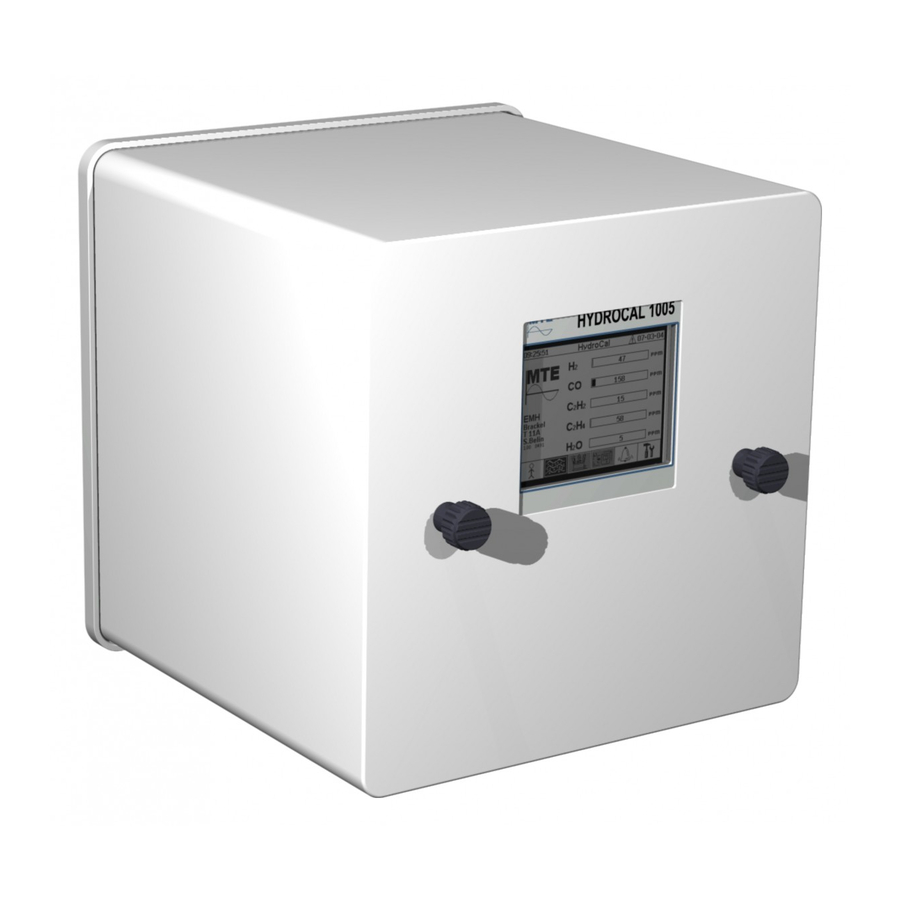
Hardware components of HYDROCAL 1005 Front view of HYDROCAL1005 On the front side of the HYDROCAL1005 unit the following operating elements are available. LCD-display with 240 x 320 pixels Screw mounting to mount the cover Alphanumeric keyboard to enter numbers and text... -
Page 17: Rear Side Of Hydrocal1005 Unit
Rear side of HYDROCAL1005 unit Measuring sensor with an internal thread of 1½ (DIN ISO 228: G 1½) or optionally (NPT 1½) HYDROCAL 1005 Manual for Installation and Operation Page 15/111... - Page 18 … 276 VAC Entrance for power supply 88 VAC … 390 VDC Optional: 88 VDC max. 350 VA, 50/60 Hz Then, power supply must be connected as follow : o Brown o Blue o Green - yellow (PE) System outlet for digital and analogue inputs and outputs Communication outlet for communication via analogue or GSM/GPRS-modem...
-
Page 19: Connections On The Measuring And Controller Card
Connections on the measuring and controller card Connector ST13: 4 x Valve Control Connection for valve control HYDROCAL 1005 Manual for Installation and Operation Page 17/111... - Page 20 Connector ST14: Pumps Oil Air Connection for pumps oil air control Connector ST11: Oil Level / Oil-Flow Connection for oil level / oil flow control Connector ST3: Humidity Temperature Connection for humidity temperature control Connector KL1: Power supply Note: The connection [5] is connected to a filter module from …...
- Page 21 Connector ST12: Heating Connection of the heating resistors, depending from the supply voltage Connector KL302: Interface RS485 and Modem X7:1 (OUT B RS485 X7:2 (OUT A RS485 X7:3 GNDIO Signal ground shield X7:4 Phone X7:5 Phone A Connector KL301: Analogue Outputs 4….
- Page 22 Connector KL102: Analogue AC Inputs Option) [10] 6 x 0 ... 80V +20% 6 x 0/4 … 20mA +20% (Analogue AC input 1 X10:1 (Analogue AC input 1 X10:2 (Analogue AC input 2 X10:3 (Analogue AC input 2 X10:4 ...
- Page 23 [14] ETHERNET connector Copper-wired Fibre-optical These sockets are connected with the back plane. It means that normally only con- nection on back plane is needed [15] Measuring cell connector HYDROCAL 1005 Manual for Installation and Operation Page 21/111...
-
Page 24: Measurement And Extraction Components
Measurement and extraction Components Capacitive Sensor F0 (ZERO) Capacitive Sensor FI (Level 1) Capacitive Sensor FII (Level 2) Valve V6 (Safety) Flow meter (Flow IN / OUT) Valve V1 (Filling / Circulation / Draining) Valve V3 (Vacuum Generation / Ventilation) Compressor K1 Valve V4 (Pressure / Ventilation) [10]... - Page 25 HYDROCAL 1005 Manual for Installation and Operation Page 23/111...
-
Page 26: Software On Hydrocal Unit
Software on HYDROCAL unit General information The gas-in-oil analyzer HYDROCAL1005 is based on a microprocessor controlled measuring sys- tem. A 32 Bit „Coldfire“ processor with a clock frequency of 240 MHz (bus clock 80 MHz) is used. The software has been developed with the language „C“. The system has a flash memory of 16 / 32 / 64 Mbyte for measuring data. -
Page 27: Operation Cycles
4.3. Operation Cycles This chapter describes each process steps and provides information in regards to the safety functions as The consequence of all errors is that the cycle will be interrupted immediately and well as how to reset errors. all valves will be closed. For all observed errors, you can acknowledged them by pressing button ... -
Page 28: Depression
4.3.2 Depression For pressure compensation of the measurement chamber Step Status of the components Capacitive Sensor F0 “not active” Capacitive Sensor FI “not active” Capacitive Sensor FII “not active” Valve V6 “closed” Flow meter “not active” Valve V1 “circulating” Valve V3 “open” Compressor K1 “active”... -
Page 29: Leak Detection
4.3.3. Leak detection During the leak detection cycle the pressure stability of the complete system is checked Step Status of the components Capacitive Sensor F0 “not active” Capacitive Sensor FI “not active” Capacitive Sensor FII “not active” Valve V6 “closed” Flow meter “not active”... -
Page 30: Filling To Level 1
4.3.4. Filling to level 1 Step Status of the components Capacitive Sensor F0 “active” Capacitive Sensor FI “active” Capacitive Sensor FII “not active” Valve V6 “open” Flow meter “active” Valve V1 “draining / filling” Valve V3 “closed” Compressor K1 “not active” Valve V4 ”closed”... -
Page 31: Degassing
4.3.5. Degassing Step Status of the components Capacitive Sensor F0 “active” Capacitive Sensor FI “active” Capacitive Sensor FII “not active” Valve V6 “closed” Flow meter “not active” Valve V1 “draining / filling” Valve V3 “closed” Compressor K1 “not active” Valve V4 ”closed” Valve V2 “closed”... -
Page 32: Filling To Level 2
4.3.6. Filling to level 2 Step Status of the components Capacitive Sensor F0 “active” Capacitive Sensor FI “active” Capacitive Sensor FII “active” Valve V6 “open” Flow meter “active” Valve V1 “draining / filling” Valve V3 “closed” Compressor K1 “not active” Valve V4 ”closed”... -
Page 33: Measurement
4.3.7. Measurement Step Status of the components Capacitive Sensor F0 “active” Capacitive Sensor FI “active” Capacitive Sensor FII “active” Valve V6 “closed” Flow meter “not active” Valve V1 “circulating” Valve V3 “closed” Compressor K1 “not active” Valve V4 ”closed” Valve V2 “closed” [10] Pump P1 “not active”... -
Page 34: Flushing
4.3.8. Flushing Step Status of the components Capacitive Sensor F0 “active” Capacitive Sensor FI “active” Capacitive Sensor FII “active” Valve V6 “closed” Flow meter “not active” Valve V1 “circulating” Valve V3 “open” Compressor K1 “active” Valve V4 ” open” Valve V2 “closed” [10] Pump P1 “not active”... -
Page 35: Draining
4.3.9. Draining Step Status of the components Capacitive Sensor F0 “active” Capacitive Sensor FI “active” Capacitive Sensor FII “active” Valve V6 “open” Flow meter “active” Valve V1 “draining / filling” Valve V3 “open” Compressor K1 “active” Valve V4 ” open” Valve V2 “open”... -
Page 36: Wait
4.3.10. Wait Step Status of the components Capacitive Sensor F0 “not active” Capacitive Sensor FI “not active” Capacitive Sensor FII “not active” Valve V6 “closed” Flow meter “not active” Valve V1 “circulating” Valve V3 “closed” Compressor K1 “not active” Valve V4 ”closed” Valve V2 “closed”... -
Page 37: Operation Of Hydrocal1005 By Its Keyboard
Operation of HYDROCAL1005 by its keyboard The HYDROCAL1005 unit when in use can be operated by its built-in keyboard. For this its external housing must be removed. Loosen the knurled thumb screws on the front side and remove carefully the housing. The unit can then be operated by the keyboard as shown below:... -
Page 38: Main Menu
Main menu After connection of the HYDROCAL1005 unit to the power supply, the main menu appears on the display. The actual measuring values of concentration for hydrogen, carbon monoxide, acetylene, ethylene and moisture in the oil are displayed. If other sensors are connected or an un- acknowledged alarm exists, then the display will change every 5 seconds (can be also changed in setup menu) to these measuring values. -
Page 39: Extraction Menu
Extraction Menu Please refer chapter 2.6.”Installation completion” Display of stored „Gas-in-oil“measuring values In the menu „Gas-in-oil“ an overview in the form of a bar chart with the composition of measured gases in the oil are shown. The values for H , CO and H O indicate their actual meas- urement values of the total gas content. -
Page 40: Table Presentation
Following functions are available: Scroll graph to the right Scroll graph to the left Zoom-out with minimum resolution of 3 days / page Zoom-in with maximum resolution of 8 hours / page Go to table presentation Exit 4.7.2 Table presentation After selection of presentation in form of a table, the measured values are shown with time and cur- rent record number. -
Page 41: Status Of Alarms
Status of alarms In the menu status of all programmed alarms are presented in a table. All alarms defined are shown together with their status. In the column „Date / Time” the last change of status is shown. The followings alarm statuses are available: ... -
Page 42: Device Set - Up
Device set – up First of all, you can define the application language while selecting it by the keyboard. You can choice between: English, German, French, Russian, Polish and Turkish. Before any amendment of settings can be made, the system asks for the password (Default pass- word is 999). -
Page 43: Menu Transformer Data Setup
4.9.1 Menu Transformer data setup This data is not necessarily required for operation of the unit. In the menu „Transformer Setup”, input of correction factor, Hot-Spot Calculation as well as Ageing Rate / Loss-of-Life Calculation are pos- sible. Parameters can be set only on the device not in HydroSoft. 4.9.1.1. -
Page 44: Hot Spot Calculation
4.9.1.1 Hot Spot calculation HYDROCAL1005 can calculate the Hot-Spot temperature. For this calculation, it is important to know that system needs external sensor references. These references are: minimum one of Load Current, Top oil Temperature as well as Cooling Stage (this last reference is not necessary required but can improve the calculation). - Page 45 4.9.1.1.1 External Sensors After selection of the external sensor submenu, following screen will be displayed: By operation of the arrow keys ( ) the different fields can be chosen. First of all, you must define each field with required information. ...
-
Page 46: Ageing Rate / Loss Of Life
4.9.1.1.2 Cooling stage #1 By operation of the arrow keys ( ) the different fields can be chosen. First of all, you must define each field with required information. Followings information must be entered: Cooling stage #1 condition o Sensor reading less / equal: in mA ... -
Page 47: Configuration Of Analogue Outputs
Configuration of analogue inputs (external sensors) The HYDROCAL1005 has a total of 14 analogue inputs. The first six inputs are for bushing sensors and allow an AC signal of either 0 .. 20 mA or 0 .. 80 V (configurable by jumper). The next four inputs are for external sensors and a DC signal of 0/4 .. - Page 48 External sensors with standard output signals (0(4)...20mA) can be connected to the HYDRO- CAL1005 analogue inputs. Note: No power supply is available for external sensors. First an input number must be selected. The first 10 input numbers are assigned to the analogue in- puts (1 ..
- Page 49 Selection of different input possibilities for the input mode [Mode], and the unit [Unit] - See below. Store alarm configuration and exit Exit without storage The following inputs signal can be selected by pressing the button: The first 6 can be set-up in 0..80VAC, 0..20mA AC, 0..20 mA or 4..20 mA ...
-
Page 50: Configuration Of Alarms And Digital Outputs
Configuration of alarms and digital outputs The HYDROCAL1005 unit has 10 digital outputs for alarms. The first 5 (Out1 ...5) are relay outputs. The „on“ status is closed and the „off“ status is open (output #1 can be configured for reverse opera- tion by a jumper on the circuit board). - Page 51 After a measuring variable has been selected and opened with for configuration, the following functions are available: Selection of different input possibilities for the alarm mode (mode), Action (action1..2) and choice of the output (clamp1..2) Activation of input over alphanumeric keyboard for the values: Alarm limit (Level1..2), Delay (Delay1..2) Scroll up Scroll down...
- Page 52 For example: if CO Alarm is setup as follow (delay 1: 10min and delay 2: 20min) In the event of alarms, CO alarms will be activated as follow: Note: CO measurement interval is 20 min. The following actions can be selected by pressing the button: ...
-
Page 53: Unit Setup
Out, hold & SMS: An entry in the history of alarms is made; this has to be confirmed (see history of alarms) and an output is switched on (If the measured value exceeded the configured limits in the field "Level 1 & 2"). The status „on“ described above is activated. If the measured value for this output falls under the limit, the output remains switched on. -
Page 54: Digital Output Test
4.9.5.1 Digital Output Test This is for Test of the 10 Digital Outputs. For testing the 5 alarms relay outputs, please check Fields KL 402 #. For testing the 5 alarms opto-coupler outputs, please check Fields KL 103 #. 4.9.5.2 Device options The configuration of the Backlight display as well as User Name and Password (String and Numeric Password) are made in the following menu:... -
Page 55: Configuration Of User Settings
The activation of the reset button will perform a software reset of the device. 4.9.5.3 Date. Time & Clock Settings The HYDROCAL1005 has a sub menu allowing configuration of time, date as well as clock HYDROCAL 1005 Manual for Installation and Operation Page 53/111... - Page 56 The following functions are available: Scroll up / down marking Enter button: selection of active menus or submenus Store the configuration and exit Exit Input of time in the field ""System Time" is made in - hours - minutes - seconds. For a double point, used the button.
-
Page 57: Configuration Of The Communication
The HYDROCAL1005 has a universal GMT clock in order to modify the time zone. The time zone setup in the field "Clock offset" is made by button. The time zone values are be- tween -6 and +6 hours. Variable „Custom" allows manual setup in the field on the right side. Input of time is made in - hours - minutes -. -
Page 58: Ethernet Setup
Status information activation Scroll up / down marking Enter button: selection of active menus or submenus Exit Note: on the main display, you have the currently communication status. 4.9.5.5 Ethernet setup The device is equipped with an Ethernet interface to allow the integration into a TCP/IP local area network. -
Page 59: Alert Sms Setup
4.9.5.6 Alert SMS setup The configuration of the alert SMS transmission is made in the following menu if HYDROCAL1005 is equipped within an on-board GSM. This function allows sending SMS in correlation with beforehand definite alarms for gas-in-oil concentrations, temperatures as well as for external sensors values. -
Page 60: Internal Modem Setup
4.9.5.7 Internal modem setup The modem configuration is made in the following menu if HYDROCAL1005 is equipped within an on-board GSM or Analogue modem. The following functions are available: Scroll up / down marking... -
Page 61: Rs 232 / Rs 485 Setup
Input of Number of Ring before answer in the field "No. of RINGs be fore Answer:" is made by button. Input of Timeout in the field ""Idle Hang-Up Timeout [s]" is made in - hours - minutes - sec- onds. For a double point, used the button. - Page 62 This section illustrates different ways to communicate with HYDROCAL devices. There are the fol- lowing main connection / communication scenarios: Host (PC) with one HYDROCAL device via RS232, RS485 or via Modem Point-to-Point Host (PC) with many HYDROCAL devices via RS485 bus RS485-Bus ...
- Page 63 A. Point to Point A point-to-point connection / communication is the simplest setup. The host (PC) is connected di- rectly to one HYDROCAL device. The connection can use the RS232, the RS485 or the modem. The default configuration for a HYDROCAL device assumes a point-to-point connection. The same ap- plies to HydroSoft.
- Page 64 For communication with a HYDROCAL device only the two-wire half-duplex mode is of interest. This mode requires a kind of send/receive-control which is either ART (Automatic Receive Transmit con- trol) or a manual control (e.g. via the RTS signal). Further the adapter may echo the send out data. The two checkboxes in the HydroSoft Connection dialog must mirror the properties of the adapter: ...
- Page 65 B. RS485-Bus Using the RS485 interface it is possible to connect more the one HYDROCAL to a host. Nonetheless it is only possible to communicate with one device at a time. The illustration below shows the sche- matic topology. Remark: The host (PC) must only be present once (the host connected via the TCP/IP adapter is only present to show an alternate way to connect to the RS485 bus, as it is offered by third party network-to-serial bridges).
- Page 66 In the HydroSoft connection dialog: Use "Connect via:" "Com-Port" Select RS485 baudrate chosen for the devices Check RS485 Set RS485 related checkboxes are required by the adapter (see also: “Answer delay”) Enter correct bus address C.
- Page 67 On HYDROCAL device: Configure the device as “Bus Bridge” Set an unique address (1..254). Note: Communication with HYDROCAL1005 can be made right now with up to 32 units Setup “Answer Delay” as required by the RS485 adapter in use ...
-
Page 68: Modbus
4.9.5.9 MODBUS MODBUS via serial interfaces If one or more HYDROCAL devices shall be integrated into a SCADA System for online monitoring, the MODBUS communication setup might be applicable. MODBUS is currently not supported by Hy- droSoft, but the setup is shown here for completeness As a reference example, the setup of an ADAM-4572 1-port Modbus®... - Page 69 This is an edit field to enter the device address. For MODBUS, values in the range from 1 to 247 are allowed. For the proprietary HYDROCAL protocol the addresses can be configured from 1 to 254. Note: Communication with HYDROCAL1005 can be made right now with up to 32 units Baud rate, Data Bits, Parity and Stop Bits These toggle buttons allow adjusting the coding format of the serial interface for MODBUS protocol.
- Page 70 I. Function, Register and Address Mapping The following MODBUS functions, register- and address ranges are used: Modbus- Modbus- Register HydroCal Function Address Address Code Dec. / Hex (5 Digit Dec.) 0x02 Alert status Read 1000 / 3E8 11001 Alert #1 Discrete Inputs 1015 / 3F7...
- Page 71 Modbus- Modbus- Register HydroCal Function Address Address 1) Code Dec. / Hex (5 Digit Dec.) 0x04 Alert status Read 3000 33001 Alert #1 Input Registers 3015 33016 Alert #16 The full alert status information is returned. no alert level 1 alert (not active) level 2 alert (not active) active level 1 alert active level 2 alert...
- Page 72 Currently the following assignment of sensor numbers applies: gas sensor H gas sensor C gas sensor C gas sensor CO temperature sensor (measurement chamber) temperature sensor (oil) humidity/moisture - reserved - daily trend gas sensor H daily trend gas sensor C daily trend gas sensor C daily trend gas sensor CO weekly trend gas sensor H...
- Page 73 I. MODBUS/RTU via RS232 (using QuickMod) RS232 only available for service purposes This test of HYDROCALMODBUS/RTU via RS232 was executed using the QuickMod application. Connection, setup and results are shown below. Physical Connection HYDROCAL and QuickMod Connection Setup: ...
- Page 74 QuickMod Monitor II. MODBUS/ASCII via RS232 (using Modpoll) RS232 only available for service purposes This test of HYDROCALMODBUS/ASCII via RS232 (RS232 only available for service purposes) executed using the Modpoll application. Connection, setup and results are shown below. Physical Connection ...
- Page 75 III. MODBUS/RTU via RS485 (using QuickMod) This test of HYDROCALMODBUS/RTU via RS485 was executed using the QuickMod application and the Roline RS2327RS485 adapter (12.02.1028). Connection, setup and results are shown be- low. Physical Connection The RS232-to-RS485 adapter is configured for 2-wire (referred to as MultiDrop Half Duplex in the adapter manual).
- Page 76 QuickMod Monitor IV. MODBUS/RTU on RS485-Bus (using Modpoll) This test of HYDROCALMODBUS/RTU on RS485 bus was executed using the Modpoll application and the ADAM-4572 Ethernet Data Gateway. It demonstrates the ability to connect multiple HY- DROCAL devices to an RS485 bus. Connection, setup and results are shown below. ...
- Page 77 HYDROCAL(only device #90) and ADAM-4572 Setup: HYDROCAL is set up without an answer delay. Each HYDROCAL on the bus has its own unique address (#90 .. #93, #0 reserved for the bus master). The timeout for ADAM-4572 can be short. The answer of HYDROCAL is received within less than 100 ms and the ADAM-4572 uses ART that does not require additional delay.
-
Page 78: Windows Software Hydrosoft
Windows Software HydroSoft Purpose of the program HydroSoft is a program compatible with MS Windows for use with HYDROCAL1005 to provide a comprehensive transformer monitoring system. HydroSoft not only reads and processes the data of HYDROCAL1005 but can also used in the configuration of the HYDROCAL1005 unit. The program is... -
Page 79: Installation
Installation All components for installation of HydroSoft software package are available on the CD. All compo- nents of the software should be installed by the installation program. Put the CD into the drive and start by Setup.exe. Now the installation program guides you through the different steps of the installation. -
Page 80: Adaptation Of Installation
The program HydroSoft works together with the HYDROCAL1005 unit. The main functions of the program are: Reading of data from HYDROCAL1005. The data can be read out through the interface RS 485 / Ethernet or from a modem integrated in the HYDROCAL1005 unit (option). -
Page 81: Preparation / Rename Of A New Customer List
Preparation / rename of a new customer list Information is presented in a “tree” format with the customer being at the top. Within a customer, transformer stations are defined and within a transformer stations, transformers followed by HY- DROCAL1005’s are defined. See below. A customer list is opened automatically by the program. -
Page 82: Opening A New Transformer Station
Opening a new transformer station After the customer list has been renamed, a file for a new transformer station can be opened as indi- cated under chapter 4.7 „File->Customer->New Station“ after selection of the customer list. The number of stations is not limited. After opening a file for a new transformer station, the address of the station can be entered. - Page 83 5.9.2) Online Sensors: A direct/online visualisation of the measuring data can be made HYDROCAL1005 settings plus alarms and external sensors can be configured. (see chapter 5.10) After opening a transformer file and entering its data, connection/communication settings should be entered.
-
Page 84: Modem Settings
GSM network. Under these circum- stances a waiting time of 5 minutes is recommended before re-sending of data. This time is required to restart the modem in the HYDROCAL1005 and to make a new connection to the GSM network. -
Page 85: Alert Setup
In such a case, the measuring result can have additional error deviations. A total 16 alarms can be defined on the HYDROCAL1005 unit. If several alarms use the same output line, the status of alarms will be connected by an „OR“- statement, resulting to activate the corre- sponding output if an alarm is triggered. - Page 86 Selection is made by the menu and with right mouse click or by „View->View As->...“ In the views „List“ and „Symbol“, the following dialogue can be opened by double clicking on one of the alarms (in view „Details“ it is not possible to open this dialogue): First the mode of alarms must be selected under „Alert Mode“.
- Page 87 The star indicates that modifications have been made; this must be transferred to the HYDROCAL1005 unit for activa- tion. This means, the settings indicated are not identical to those of HYDROCAL1005. With next connection, it is requested whether the settings on HYDROCAL1005 unit shall be updated (see chapter 5.11).
-
Page 88: External Sensors (See Also Chapter 4.7.3)
5.10.2 External sensors (see also chapter 4.7.3) In the menu , the settings of external sensors are modified. The form of presenta- tion can be chosen as under alarms as „List“ „Symbol“ „Details“ The menu „Sensor properties“ is opened by double clicking on a value or a symbol. The settings of internal sensors cannot be modified and are therefore greyed out. -
Page 89: Alert Sms Setup
Data in the tree are changed after modification of sensor settings. The star indi- cates that modifications have been made; these must be transferred to the HYDROCAL1005 unit for activation. This means, the settings indicated are not identical to those of HYDROCAL1005. With next connection, it is requested whether the settings on HYDROCAL1005 unit shall be updated (see chapter 5.11). - Page 90 . The star indicates that modifications have been made; these must be transferred to the HYDROCAL1005 unit for activation. This means, the settings indicated are not identical to those of HYDROCAL1005. With next connection, it is requested whether the settings on HYDROCAL1005 unit shall be updated (see chapter 5.11).
-
Page 91: Input Of Dga Level Adjustment
5.10.4 Input of DGA Level Adjustment Results of laboratory analysis can be introduced in the menu . These can be used for calculation of correction factors for definition of the gas content. After opening of transformer menu page, the correction factors are shown in the fields „Cur. Offset“. For the input of results of laboratory analysis, first the date of analysis should be entered in the field „Sample Date“. -
Page 92: Analog Output Setup
. The star indicates that modifications have been made; these must be transferred to the HYDROCAL1005 unit for activation. This means, the settings indicated are not identical to those of HYDROCAL1005. With next connection, it is requested whether the settings on HYDROCAL1005 unit shall be updated (see chapter 5.11). -
Page 93: Digital Output Setup
Note: "None " means that the function is not activated. Moreover, you can synchronize the date and time on each HYDROCAL1005 with PC clock while confirming by a click on the field "Synchronize with PC clock" in the following communication box:... -
Page 94: 5.10.5.1. Ethernet
. The star indicates that modifications have been made; these must be transferred to the HYDROCAL1005 unit for activation. This means, the settings indicated are not identical to those of HYDROCAL1005. With next connection, it is requested whether the settings on HYDROCAL1005 unit shall be updated (see chapter 5.11). -
Page 95: 5.10.5.2. Modbus-Tcp
Modbus communication. 5.10.5.3. MODBUS If one or more HYDROCAL1005 devices shall be integrated into a SCADA System for online moni- toring, the MODBUS communication setup might be applicable. MODBUS is currently not supported by HydroSoft, but the setup is shown here for completeness ... - Page 96 In the dialogue, the following actions can be selected: „Read Configurations“: Read configurations from HYDROCAL1005 unit. This means that the modifications of alarms and sensor settings made in HydroSoft (indicated by a star) are overwrit- ten by the settings active in the HYDROCAL unit.
- Page 97 The standard timeout is 5 seconds, for Modem connections a timeout of 20 seconds is recom- mended. After confirmation by the “Start“ – button, the status of communication will be presented in the win- dow. By pressing the button connection is interrupted.
-
Page 98: View Of Results
5.12 View of results To view measured results read out, you must select the „History“ field of the respective transformer. Three operation elements are available (see below picture) 5.12.1 Sensor selection This window shows the different sensors available on the HYDROCAL unit. Besides the sensor name, the last measuring value is displayed;... -
Page 99: Result Window
5.12.3 Result window The result window shows all sensor results activated for presentation. The results are presented in form of time trend or graph tables. When on the result window, click the right mouse button to open the menu and select the form desired. There is also the possibility to activate the print-function (only from trend..) or export function (only from graph table) and to fade out the sensor and time selec- tion. -
Page 100: View Of Alarm Status
5.13 View of alarm status To view alarms, you must select the list „Alert“ under the corresponding transformer. The operation elements are same as indicated under „View of results. Under „Alarm selection“ the different alarms defined and selected on the HYDROCAL unit can be ac- tivated in form of time trend and table views. -
Page 101: Alarm Window
5.13.3 Alarm window The alarm window shows all alarm status activated for presentation. The results are presented in form of a time trend chart or a table. When on the alarm window, click right mouse button to open the menu and select the form desired. There is also the possibility to activate the print-function (only from time trend chart) or export function (only from table view) and to fade out the sensor and time range selection. -
Page 102: Online Sensors
5.14 Online Sensors To view a direct/online visualisation, you must select the list „Online Sensors“ under the correspond- ing transformer. The operation elements are same as indicated under „View of results. Under „visible sensors“ the different measuring values (H - CO and H O) and external sensors defined in “Sensor setup”... -
Page 103: Rs 485 Wiring
RS 485 Wiring This chapter contains information for the wiring of the RS485 connection. RS485 The RS485 interface is implemented as a three-wire interface. The three signal wires must be clamped onto connector #7, pin 1, pin 2 and pin 3 inside of the HYDROCAL. Care must be taken for the right polarity. -
Page 104: Hydrosoft Scheduler
HYDROSOFT Scheduler General Up to version 1.0.16 the transfer of the history data from the HYDROCAL device into the HydroSoft application could only be started manually. With version 1.0.18 an automatic read-out of the history data is possible. This is managed by the new scheduler integrated into HydroSoft. -
Page 105: Connection Scheduler Dialog
7.2.1.1 Connection Scheduler Dialog The connection scheduler dialog allow to configure the automatic history data read-out. (For further details on the setting see 7.2.4, Internal Operation.) The checkbox Scheduled Data Read-Out en- or disables the automatic history data update. ... -
Page 106: Transformer
7.2.2.2 Transformer The standard icon is used for transformers that are not activated for scheduled history data update. The read-out status is good. (The number of connection failures is less than 3.) The read-out status is bad. A connection has been tried several times but was not suc- cessful. -
Page 107: Hydrosoft And The Windows Task Scheduler
The scheduler has started the communication for Transformer1 in Station1 (all related icons indicate the active scheduler communication). The communication buttons in the transformer window control area are disabled. The control area is shown with an alternate background colour to indicate the busy status. -
Page 108: Command Line Options For Windows Task Scheduler
7.2.3.1 Command Line Options for Windows Task Scheduler HydroSoft comes with two new command line options for use in conjunction with the scheduled his- tory data update. Example: <path>\Hydrosoft -IdleClose 0:15:00 -Minimized 7.2.3.2 IdleClose The IdleClose command line option can be given to let the application terminate after all history data updates have be carried out. -
Page 109: Data Directory Lock
7.2.5 Data Directory Lock HydroSoft now protects the data directory by a lock. Once an instance of HydroSoft is working on a data directory no second instance of HydroSoft can operate on the same data. This locking is introduced to keep data integrity in case a user is running HydroSoft and a back- ground instance of HydroSoft (started via the Windows task scheduler) also tries to work on the data. -
Page 110: Technical Data Hydrocal1005
Technical data HYDROCAL1005 General … 276 VAC Auxiliary supply: 88 VAC … 350 VDC Optional: 88 VDC Power consumption: max. 350 VA Housing: Aluminium Dimensions: W 263 x H 263 x D 257 mm Weight: Approx. 13.5 kg Operation temperature: -55°C ... - Page 111 Analogue Inputs and Digital Outputs (optional) Accuracy Remarks Analogue DC Inputs (External sensors) Type Range of the measuring value 0.5 % Current DC 4 x 0/4 ... 20 mADC Accuracy Remarks Analogue AC Inputs (Cap. HV Bushing) Type Range of the measuring value ...
-
Page 112: Dimensional Drawings Hydrocal1005
Dimensional drawings HYDROCAL1005 HYDROCAL 1005 Manual for Installation and Operation Page 110/111... - Page 113 HYDROCAL 1005 Manual for Installation and Operation Page 111/111...
Need help?
Do you have a question about the HYDROCAL1005 and is the answer not in the manual?
Questions and answers