Table of Contents
Advertisement
Quick Links
Advertisement
Table of Contents

Related Manuals for iS5 iES10GF Series

Summary of Contents for iS5 iES10GF Series
- Page 1 Intelligent 10 Port Managed Ethernet Switch iES10G(F) Series User’s Manual Version 1.5 January 2016 iS5 Communications Inc. #3-7490 Pacific Circle, Mississauga, Ontario, L5T 2A3 Tel: + 905- 670- 0004 Fax: + 289- 401- 5206 Website: www.iS5Com.com E-mail: support@iS5Com.com...
-
Page 2: All Rights Reserved
Registered Trademarks iS5Com™, is a trademark of iS5 Communications Inc. Other designations in this manual might be trademarks whose use by third parties for their own purposes would infringe the rights of the owner. Linux® is the registered trademark of Linus Torvalds in the U.S. and other countries. -
Page 3: Table Of Contents
Front Panel LED’s ..........................11 Bottom View Panel..........................12 Rear Panel .............................. 13 Side Panel ............................... 14 Cables ......................... 15 Ethernet Cables ............................15 4.1.1 100BASE-TX/10BASE-T Pin Assignements ............... 15 SFP ................................ 16 Console Cable ............................17 iS5 Communications Inc. - Page 4 5.1.9.1 SNMP – Agent Setting ......................43 5.1.9.2 SNMP – Trap Setting ......................45 5.1.10 Traffic Prioritization ......................46 5.1.11 Multicast ..........................50 5.1.11.1 IGMP Snooping ........................50 5.1.11.2 Multicast Filter ........................51 5.1.12 Security ..........................52 iS5 Communications Inc.
- Page 5 6.14 Commands Set List—SYSLOG, SMTP, EVENT command set ........... 85 6.15 Commands Set List—SNTP command set ................86 6.16 Commands Set List—iRing command set ................87 Technical Specifications ..................89 APPENDIX A: IES10G(F) MODBUS INFORMATION ..........92 iS5 Communications Inc.
-
Page 6: Caution: Laser
This product contains no user-serviceable parts. Attempted service by unauthorized personnel shall render all warranties null and void. Changes or modifications not expressly approved by iS5 Communications Inc. could invalidate specifications, test results, and agency approvals, and void the user's authority to operate the equipment. -
Page 7: Introduction
Single Input Hi-voltage (HV) AC/DC input (85-264VAC, 88-300VDC) with Single (10-48VDC) backup Wide Operating Temperature: -40 C to +85 Storage Temperature: -40 C to 85 Operating Humidity: 5% to 95%, non-condensing Chassis: IP-40 Galvanized Steel 7 x 10/100Base-T(X) Ethernet ports iS5 Communications Inc. -
Page 8: Hardware Installation
Step 1: Slant the switch and hook the top 2 catches of the metal bracket onto the top of the DIN-Rail. DIN-Rail Bracket Step 2: Push the bottom of the switch toward the DIN-Rail until the bracket snaps in place. iS5 Communications Inc. -
Page 9: Wall Mount Installation
Mounting the iES10G(F) on a Wall or Panel Option 1: Fix mounting brackets to the side of switch using the 4 screws included in the package. Option 2: Fix mounting brackets to back of switch using 4 screws included in the package. iS5 Communications Inc. -
Page 10: Hardware Overview
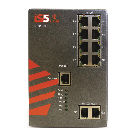
Use a RS232 to RJ45 cable assembly to manage switch. Reset (8) Push and hold the reset button for 2-3 seconds to reset the switch. Push and hold the reset button for 5 seconds to reset the switch into Factory Default. 9 (Ports P1- P7) iS5 Communications Inc. -
Page 11: Front Panel Led's
Port working at full duplex. Gigabit Ethernet ports (combo ports) Port link up. LNK/ACT Green Blinking Data transmission. Speed Amber Port operating at 100Mbps Gigabit SFP ports (combo ports) Shown Port link up. LNK / ACT Green Blinking Data transmission. iS5 Communications Inc. -
Page 12: Bottom View Panel
Ground connects to both power supply surge grounds via a removable jumper. PWR2 (L) – Live Connect to the (Live) terminal of Power supply 2 or backup DC power source. PWR2 (G) – Ground Power supply 2 or backup DC power source ground iS5 Communications Inc. -
Page 13: Chassis Ground Connection
Equipment must be installed according to the applicable country wiring codes. Rear Panel The components on the rear of the iES10G(F) are shown below: 1. Screw holes (4) for wall mount kit. 2. DIN-Rail mount iS5 Communications Inc. -
Page 14: Side Panel
User Manual Side Panel The components on the side of the iES10G(F) are shown below: 1. Screw holes (4) for wall mount kit. iS5 Communications Inc. -
Page 15: Cables
4.1.1 100BASE-TX/10BASE-T Pin Assignements With 100BASE-TX/10BASE-T cable, pins 1 and 2 are used for transmitting data, and pins 3 and 6 are used for receiving data. RJ45 Pin Assignments: Pin Number Assignment Not used Not used Not used Not used iS5 Communications Inc. -
Page 16: Sfp
Multimode LC connectors (0 to 550m, 850 nm with 50/125 µm, and 62.5/125 µm fiber), or Singlemode LC connectors. Note : the Tx port of Switch A should be connected to the R(x) port of Switch B. Switch (A) Switch (B) Fiber cord iS5 Communications Inc. -
Page 17: Console Cable
Connect to the PC via the RS-232/DB9 connector and the RJ45 connector to the console port of the switch. Console Cable pin assignments: PC pin out (male) assignment DB9 to RJ 45 Pin #2 RD Pin #2 TD Pin #3 TD Pin #3 RD Pin #5 GD Pin #5 GD iS5 Communications Inc. -
Page 18: Web Management
The default value is as below: IP Address: 192.168.10.1 Subnet Mask: 255.255.255.0 Default Gateway: 192.168.10.254 User Name: admin Password: admin System Login Launch the Internet Explorer. Type http:// and the IP address of the switch. Press “Enter”. iS5 Communications Inc. -
Page 19: Main Interface
User Manual The login screen appears. Key in the default username and password. Click “Enter” or ”OK”. The main interface of the Web-based management appears. Login screen Main Interface Main interface iS5 Communications Inc. -
Page 20: System Information
System Information The system information will display the configuration of Basic Setting/Switch Setting page. Enable Location Alert Click , PWR1 and PWR2 LED’s of the switch will start to flash together; Click , the LED’s stop flashing. iS5 Communications Inc. -
Page 21: Front Panel
Description System Name Assign a name to the switch. The maximum length is 64 bytes System Description Displays the description of the switch. System Location Assign the switch a physical location. The maximum length is 64 bytes iS5 Communications Inc. -
Page 22: Admin Password
Key in the new username (The default is “admin”) New Password Key in the new password (The default is “admin”) Confirm password Re-type the new password. Apply Click “Apply” to activate the configurations. Help Show help file. iS5 Communications Inc. -
Page 23: Ip Setting
Assign the network gateway for the switch. The default gateway is 192.168.10.254. DNS1 Assign the primary DNS IP address DNS2 Assign the secondary DNS IP address Apply Click “Apply” to activate the configurations. Help Show help file. iS5 Communications Inc. -
Page 24: Sntp (Time)
Set up the Daylight Saving beginning time and Daylight Saving ending time. Both will be different each year. Daylight Saving Offset Set up the offset time. Apply Click “Apply” to activate the configurations. Help Show help file. iS5 Communications Inc. - Page 25 BT - Baghdad, USSR Zone 2 +3 hours 3 pm ZP4 - USSR Zone 3 +4 hours 4 pm ZP5 - USSR Zone 4 +5 hours 5 pm ZP6 - USSR Zone 5 +6 hours 6 pm iS5 Communications Inc.
-
Page 26: Lldp
The interval of resend LLDP (by default at 30 seconds) Apply Click “Apply” to activate the configurations. Help Show help file. 5.1.4.6 Modbus TCP This page shows Modbus TCP support of the switch. (For more information regarding Modbus, please visit http://www.modbus.org/) iS5 Communications Inc. -
Page 27: Auto Provision
The current configuration from the switch can either be saved to the TFTP server, or it can be restored from the TFTP server on this page. The configuration can also be saved to and restored from a file on the local PC. iS5 Communications Inc. -
Page 28: Upgrade Firmware
Upgrade Firmware allows you to update the firmware of the switch via TFTP or from your local PC. Before updating by TFTP, make sure you have your TFTP server ready, and the firmware image is on the TFTP server. The firmware can also be updated from a file on the local PC. iS5 Communications Inc. -
Page 29: Dhcp Server
Enable or Disable the DHCP Server function. Enable – the switch will act as the DHCP server on your local network. Start IP Address The dynamic IP assign range. The lowest IP address is the starting of the dynamic IP assigned range. For example: dynamic IP assigned range iS5 Communications Inc. - Page 30 Domain Name Server IP Address in the network. It is the period that the system will reset the assigned dynamic IP Lease Time (Hour) address to ensure the IP address is in use. Apply Click “Apply” to activate the configurations. Help Show help file. iS5 Communications Inc.
-
Page 31: Dhcp Server - Client List
DHCP Server Port and IP Binding interface 5.1.6 Port Setting 5.1.6.1 Port Control With this function, the system administrator can set the state, speed/duplex, flow control, and security of the port. iS5 Communications Inc. - Page 32 Supports symmetrical and asymmetrical mode to avoid packet loss when congestion occurs. Security Supports port security function. When enabled, the port will STOP learning the MAC address dynamically. Apply Click “Apply” to activate the configurations. Help Show help file. iS5 Communications Inc.
-
Page 33: Port Status
Rate Limit This function allows the system administrator to limit the traffic on all ports, including broadcast, multicast and flooded Unicast. It can also set “Ingress” or “Egress” to limit traffic received or transmitted. Rate Limit interface iS5 Communications Inc. -
Page 34: Port Trunk
The following table describes the Port Trunk Setting interface page. Label Description Group ID Select port to join a trunk group. Type Support static trunk and 802.3ad LACP. Apply Click “Apply” to activate the configurations. Help Show help file. iS5 Communications Inc. - Page 35 Description Work Ports Work ports counted (max:4 ports) Apply Click “Apply” to activate the configurations. Help Show help file. Port Trunk – Status You can check the configuration of a port trunk. Port Trunk - Status interface iS5 Communications Inc.
-
Page 36: Redundancy
Rings to avoid affecting all switches when a network topology change has been made. It is a good application when connecting two Rings. Coupling Port Set a port as the coupling port to link to the Coupling Port of the switch iS5 Communications Inc. -
Page 37: Rstp
The system also supports STP and will detect a connected device that is running STP or RSTP protocol automatically. RSTP setting The RSTP function can be enabled or disabled, and parameters set for each port via the RSTP Setting interface. iS5 Communications Inc. - Page 38 The number of seconds for a bridge to wait without receiving Spanning-tree Protocol configuration messages before reconfiguration. Enter a value between 6 and 40. Hello Time (1-10) The time the control switch sends out the BPDU (Bridge Protocol Data iS5 Communications Inc.
- Page 39 Show help file. NOTE: Follow the rule below to configure the MAX Age, Hello Time, and Forward Delay Time: 2 x (Forward Delay Time value –1) ≥ Max Age value ≥ 2 x (Hello Time value +1) iS5 Communications Inc.
-
Page 40: Vlan
VLAN groups available. Enabling 802.1Q VLAN, and all ports on the switch belong to the default VLAN, VID is 1. The default VLAN cannot be deleted. GVRP allows automatic VLAN configuration between the switch and nodes. If the switch is connected to a iS5 Communications Inc. - Page 41 Only the devices in the management VLAN can access the switch. Link type There are 3 link types: Access Link: single switch only, allows the grouping of ports by setting the same VID. Trunk Link: extended application of Access Link, allows the grouping of iS5 Communications Inc.
-
Page 42: Vlan Setting - Port Based
VLAN Configuration – Port Base interface-1 The following table describes the VLAN Configuration – Port Base interface-1 page. Label Description Click “add” to enter VLAN add interface. Edit Edit existing VLAN. Delete Delete existing VLAN. Help Show help file. iS5 Communications Inc. -
Page 43: Snmp
Network management systems learn of problems by receiving traps or change notices from network devices implementing SNMP. 5.1.9.1 SNMP – Agent Setting SNMP agent related information can be set using the Agent Setting Function. iS5 Communications Inc. - Page 44 "Community String/Privilege" are supported. Each Community String is a maximum of 32 characters. Keep empty to remove this Community string. SNMPv3User If SNMP V3 agent is selected, the SNMPv3 profiled should be set for authentication. The Username is necessary. The Auth. Password is iS5 Communications Inc.
-
Page 45: Snmp - Trap Setting
If no trap manager is defined, no traps will issued. Create a trap manager by entering the IP address of the station and a community string. To define management stations as trap managers, enter the SNMP community string and select the SNMP version. iS5 Communications Inc. -
Page 46: Traffic Prioritization
5.1.10 Traffic Prioritization Traffic Prioritization includes 3 modes: port base, 802.1p/COS, and TOS/DSCP. With the traffic prioritization function, traffic can be classified into four classes for differential network applications. The iES10G(F) supports 4 priority queues. Policy Setting interface iS5 Communications Inc. - Page 47 Use the strict priority scheme: the packets in higher queue will always be transmitted first until a higher queue is empty. Help Show help file. Apply Click “Apply” to activate the configurations. Port-based Priority interface iS5 Communications Inc.
- Page 48 User Manual Label Description Port base Priority Assign Port with a priority queue. 4 priority queues can be assigned: High, Middle, Low, and Lowest. Help Show help file. Apply Click “Apply” to activate the configurations. COS/802.1p interface iS5 Communications Inc.
- Page 49 0 to 63. DSCP value maps to 4 priority queues: High, Middle, Low, and Lowest. Apply Click “Apply” to activate the configurations. Help Show help file. iS5 Communications Inc.
-
Page 50: Multicast
IGMP queries in an IGMP application. The "Auto" mode means that the switch receiving the IGMP query is the one with lower IP address. IGMP Snooping Table Show current IP multicast list Apply Click “Apply” to activate the configurations. Help Show help file. iS5 Communications Inc. -
Page 51: Multicast Filter
Tick the check box beside the port number to include them as the member ports in the specific multicast group IP address. Show current IP multicast list. Delete Delete an entry from table. Help Show help file. iS5 Communications Inc. -
Page 52: Security
IP security MODE Enable/Disable the IP security function. Enable WEB Check the blank to enable WEB Management. Management Enable Telnet Check the blank to enable Telnet Management. Management Enable SNMP Check the blank to enable SNMP Management. Management iS5 Communications Inc. -
Page 53: Port Security
5.1.12.3 MAC Blacklist MAC Blacklist can eliminate the forwarding traffic to specific MAC addresses on the list. Any frames being forwarded to MAC addresses on this list will be discarded. Thus the target device will never receive any frames. iS5 Communications Inc. -
Page 54: 802.1X
802.1x makes the use of the physical access characteristics of IEEE802 LAN infrastructure in order to provide an authenticated and authorized device attached to a LAN port. Please refer to IEEE 802.1X - Port Based Network Access Control. iS5 Communications Inc. - Page 55 Set the time that the switch can wait for response to an EAP request/identity frame from the client before resending the request. Supplicant Timeout Set the period of time the switch waits for a supplicant response to an EAP request. iS5 Communications Inc.
- Page 56 Accept: force this port to be authorized. Authorize: the state of this port was determined by the outcome of the 802.1x authentication. Disable: this port will not participate in 802.1x. Apply Click “Apply” to activate the configurations. Help Show help file. iS5 Communications Inc.
-
Page 57: Warning
E-MAIL, or relay fault on a switch panel. 5.1.13.1 Fault Alarm When any selected fault event occurs, the Fault LED on the switch panel will light up and the electric relay will signal at the same time. Fault Alarm interface iS5 Communications Inc. -
Page 58: System Alarm
Help Show help file. System Warning – SMTP Setting SMTP is Short for Simple Mail Transfer Protocol. It is a protocol for e-mail transmission across the Internet. Please refer to RFC 821 - Simple Mail Transfer Protocol. iS5 Communications Inc. - Page 59 SYSLOG and SMTP are the two warning methods that are supported by the system. Check the corresponding box to enable the system event warning method. Please note that the checkbox cannot be checked when SYSLOG or SMTP is disabled. iS5 Communications Inc.
- Page 60 Alert when the iRing topology changes. Port Event Disable SYSLOG / SMTP event Link Up Link Down Link Up & Link Down Apply Click “Apply” to activate the configurations. Help Show help file. iS5 Communications Inc.
-
Page 61: Monitor And Diagnostics
The MAC Address aging time can be set between 0 and 3825 seconds. When the time expires, the unused MAC address will be cleared from MAC table. The iES10G(F) also supports “Auto Flush MAC Address Table When Ports Link Down”. iS5 Communications Inc. -
Page 62: Port Statistics
Auto Flush MAC Address Enable this function. Table When ports Link Down Apply Click “Apply” to activate the configurations. Help Show help file. 5.1.14.3 Port Statistics Port statistics show several statistics counters for all ports Port Statistics interface iS5 Communications Inc. -
Page 63: Port Monitoring
Check RX Source Ports out to a selected RX destination port. It also sends the frame where it normally would have gone. Note: keep all source ports unchecked to disable Port Monitoring. Port monitoring interface iS5 Communications Inc. -
Page 64: System Event Log
Click “Apply” to activate the configurations. Clear Clear all marked blank.(disable the function) Help Show help file. 5.1.14.5 System Event Log If system log client is enabled, the system event logs will be shown in this table. System Event Log interface iS5 Communications Inc. -
Page 65: Save Configuration
Factory Default interface Reset switch to default configuration. Click Reset to reset all configurations to the default value. Select “Keep current IP address setting” and “Keep current username & password” to keep current IP address, username, and password. iS5 Communications Inc. -
Page 66: System Reboot
User Manual 5.1.17 System Reboot System Reboot interface iS5 Communications Inc. -
Page 67: Command Line Interface Management (Cli)
Follow the steps below to access the console via RS-232 serial cable. Step 1) From the Windows desktop, click on Start -> Programs -> Accessories -> Communications -> Hyper Terminal. Step 2) Enter a name for the new connection. iS5 Communications Inc. - Page 68 User Manual Step 3) Select appropriate COM port number iS5 Communications Inc.
- Page 69 Step 4) Set the COM port properties to the following: 9600 Bits per second, 8 Data bits, No Parity, 1 Stop bit and no Flow control. Step 5) The Console login screen will appear. Enter the Username and Password (same as the password for the Web Browser), then press “Enter”. iS5 Communications Inc.
- Page 70 Step 1) Telnet to the IP address of the switch from the Windows “Run“ command (or from the MS-DOS prompt) as below. Step 2) The Login screen will appear. Use the keyboard to enter the Username and Password (same as the password for the Web Browser ), and then press “Enter” iS5 Communications Inc.
- Page 71 Ethernet ports. interface)while in To exist privileged global configuration EXEC mode or end. mode Symbols for Command Level Mode Symbol of Command Level User EXEC Privileged EXEC Global configuration VLAN database Interface configuration iS5 Communications Inc.
-
Page 72: Commands Set List-System Commands Set
Changes a login switch(config)#admin username xxxxxx [Username] username. (maximum 10 words) admin password Specifies a password switch(config)#admin password xxxxxx [Password] (maximum 10 words) show admin Show administrator switch#show admin information dhcpserver enable Enable DHCP Server switch(config)#dhcpserver enable iS5 Communications Inc. - Page 73 1 192.168.1.55 [Index(1..10)] [IP Address] show security Show the information of switch#show security IP security no security Disable IP security switch(config)#no security function no security http Disable IP security of HTTP switch(config)#no security http server iS5 Communications Inc.
-
Page 74: Commands Set List-Port Commands Set
Set interface ingress limit switch(config)#interface fastEthernet 2 frame type to “accept all switch(config-if)#bandwidth type all frame” bandwidth type Set interface ingress limit switch(config)#interface fastEthernet 2 broadcast-multicast-flooded-u frame type to “accept switch(config-if)#bandwidth type nicast broadcast, multicast, and broadcast-multicast-flooded-unicast flooded unicast frame” iS5 Communications Inc. - Page 75 2 configuration status switch(config-if)#show interface configuration show interface status show interface actual switch(config)#interface fastEthernet 2 status switch(config-if)#show interface status show interface accounting show interface statistic switch(config)#interface fastEthernet 2 counter switch(config-if)#show interface accounting iS5 Communications Inc.
-
Page 76: Commands Set List-Trunk Command Set
Show the information of switch#show aggregator trunk group no aggregator lacp Disable the LACP function switch(config)#no aggreator lacp 1 [GroupID] of trunk group no aggregator group Remove a trunk group switch(config)#no aggreator group 2 [GroupID] iS5 Communications Inc. -
Page 77: Commands Set List-Vlan Command Set
V Assign a trunk link for switch(vlan)#vlan 8021q aggreator 3 [TrunkID] VLAN by trunk group trunk-link tag 2,3,6,99 trunk-link tag [TaggedVID List] switch(vlan)#vlan 8021q aggreator 3 trunk-link tag 3-20 vlan 8021q aggreator Assign a hybrid link for switch(vlan)# vlan 8021q aggreator 3 iS5 Communications Inc. -
Page 78: Commands Set List-Spanning Tree Command Set
Spanning Tree Protocol (STP) topology. spanning-tree hello-time Use the spanning-tree switch(config)#spanning-tree hello-time 3 [seconds] hello-time global configuration command to specify the interval between hello bridge protocol data units (BPDUs). spanning-tree forward-time Use the spanning-tree switch(config)# spanning-tree forward-time iS5 Communications Inc. - Page 79 2 [True|False] on this interface. switch(config-if)# stp-admin-edge True stp-admin-non-stp Admin NonSTP of STP switch(config)#interface fastEthernet 2 [True|False] priority on this interface. switch(config-if)# stp-admin-non-stp False Show spanning-tree Display a summary of the switch>show spanning-tree spanning-tree states. iS5 Communications Inc.
-
Page 80: Commands Set List-Qos Command Set
Igmp-query force Set IGMP query to force switch(config)#Igmp-query force mode show igmp configuration Displays the details of an switch#show igmp configuration IGMP configuration. show igmp multi Displays the details of an switch#show igmp multi IGMP snooping entries. iS5 Communications Inc. -
Page 81: Commands Set List-Mac/Filter Table Command Set
6.10 Commands Set List—SNMP command set iES10G(F) Commands Level Description Example snmp agent-mode Select the agent mode of switch(config)#snmp agent-mode v1v2c [v1v2c | v3] SNMP snmp-server host Configure SNMP server switch(config)#snmp-server host [IP address] host information and 192.168.10.50 community public iS5 Communications Inc. -
Page 82: Commands Set List-Port Mirroring Command Set
6.11 Commands Set List—Port Mirroring command set iES10G(F) Commands Level Description Example monitor rx Set RX destination port of switch(config)#monitor rx monitor function monitor tx Set TX destination port of switch(config)#monitor tx monitor function show monitor Show port monitor switch#show monitor information iS5 Communications Inc. -
Page 83: Commands Set List-802.1X Command Set
8021x system sharekey [ID] share key global 123456 configuration command to change the shared key value. 8021x system nasid Use the 802.1x system switch(config)# 8021x system nasid test1 [words] nasid global configuration command to change the NAS ID iS5 Communications Inc. - Page 84 8021x Display a summary of the switch#show 8021x 802.1x properties and also the port sates. no 8021x Disable 802.1x function switch(config)#no 8021x iS5 Communications Inc.
-
Page 85: Commands Set List-Tftp Command Set
Enable SMTP function switch(config)#smtp enable smtp serverip Configure SMTP server IP switch(config)#smtp serverip 192.168.1.5 [IP address] smtp authentication Enable SMTP switch(config)#smtp authentication authentication smtp account Configure authentication switch(config)#smtp account User [account] account iS5 Communications Inc. -
Page 86: Commands Set List-Sntp Command Set
Show system log client & switch#show systemlog server information 6.15 Commands Set List—SNTP command set iES10G(F) Commands Level Description Example sntp enable Enable SNTP function switch(config)#sntp enable sntp daylight Enable daylight saving switch(config)#sntp daylight time, if SNTP function is iS5 Communications Inc. -
Page 87: Commands Set List-Iring Command Set
6.16 Commands Set List—iRing command set iES10G(F) Commands Level Description Example Ring enable Enable iRing switch(config)# ring enable Ring master Enable ring master switch(config)# ring master Ring couplering Enable couple ring switch(config)# ring couplering Ring dualhoming Enable dual homing switch(config)# ring dualhoming iS5 Communications Inc. - Page 88 Ring Disable iRing switch(config)#no ring no Ring master Disable ring master switch(config)# no ring master no Ring couplering Disable couple ring switch(config)# no ring couplering no Ring dualhoming Disable dual homing switch(config)# no ring dualhoming iS5 Communications Inc.
-
Page 89: Technical Specifications
Max. Number of Available VLANs: 4096 IGMP multicast groups: 1024 Port rate limiting: User Defined Security Features Enable/disable ports, MAC based port security Port based network access control (802.1x) VLAN (802.1Q ) to segregate and secure network traffic iS5 Communications Inc. - Page 90 IP-40 Galvanized Steel Housing Dimension (W x D x H) IES10G - 101.6 mm(W)x 109.2 mm(D)x 153.8 mm(H) (4x4.3 x 6.05 inch) iES10GF – 101.8(W)x163.2(D)x153.6(H) mm (4 x 6.43 x 6.05 inch) Weight (g) iES10G – 1.1 kg iS5 Communications Inc.
- Page 91 Regulatory Approvals FCC Part 15, CISPER (EN55022) class A EN61000-4-2 (ESD), EN61000-4-3 (RS), EN61000-4-4 (EFT), EN61000-4-5 (Surge), EN61000-4-6 (CS) EN61000-4-8, EN61000-4-11 Shock IEC 60068-2-27 Free Fall IEC 60068-2-32 Vibration IEC 60068-2-6 Safety EN60950-1 Warranty Warranty 5 years iS5 Communications Inc.
-
Page 92: Appendix A: Ies10G(F) Modbus Information
0x0001 Link up 0x0002 Disable 0xffff NoPort 4352-4361 PortSpeed: Port :1~VTSS_PORTS Value :0x0000 10M‐Half 0x0001 10M‐Full 0x0002 100M‐Half 0x0003 100M‐Full 0x0004 1G‐Half 0x0005 1G‐Full 0xffff NoPort 4608-4617 PortFlowCtrl Port :1~VTSS_PORTS Value :0x0000 Off 0x0001 On 0xffff NoPort iS5 Communications Inc.
Need help?
Do you have a question about the iES10GF Series and is the answer not in the manual?
Questions and answers