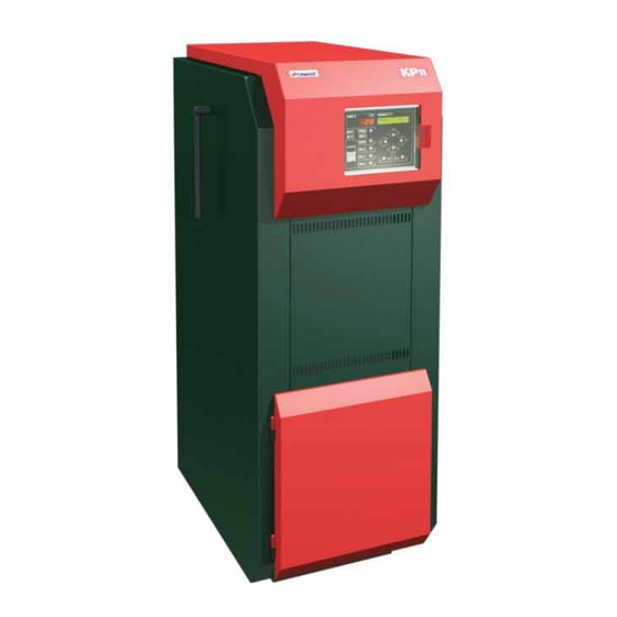
Ponast KP 10 Instructions For Operation Manual
Automatic boiler for wood pellets
Hide thumbs
Also See for KP 10:
- Instructions for operation manual (38 pages) ,
- Instructions for installation and operation manual (59 pages)
Table of Contents
Advertisement
Quick Links
Advertisement
Table of Contents

Related Manuals for Ponast KP 10


Summary of Contents for Ponast KP 10
- Page 2 Your boiler in brief: For a proper functionality, it is important to: • ensure always enough fuel in the operating bin of the boiler; • use recommended fuel; • follow the operating instructions. What to do, if the boiler is not heating - check whether the boiler is turned on (and what does it show on the display);...
- Page 3 SELECTED CHAPTERS FROM THE BOILER OPERATION FILLING THE FEEDER F1 WITH PELLETS Here are the steps how to fill fuel transportation ways by operating feeders F1 and F2, see procedure in the table below: Step button pushed the display shows Note 1.
-
Page 4: Table Of Contents
Automatic boiler for pellets – User manual TABLE OF CONTENTS IMPORTANT NOTIFICATIONS......................3 OPERATION............................4 OPERATION ............................4 FILLING THE FEEDER F1 WITH PELLETS....................5 BOILER IGNITION - ELECTRIC IGNITION....................5 BOILER IGNITION - MANUAL ....................... 6 MAINTENANCE..........................6 ANNUAL INSPECTION ........................7 CONTROL UNIT OPERATION......................9 CONTROL PANEL .......................... - Page 5 Automatic boiler for pellets – User manual OPTIONAL ACCESSORIES........................30 FEEDER F1 (FROM THE FUEL BIN)...................... 31 FUEL BIN ............................31 BOILER INSTALLATION .......................31 PLACEMENT IN THE BOILER ROOM ....................31 9.1.1 Ceramic extension grate placement ..................31 9.1.2 Ceramic shield placement ......................32 9.1.3 Ceramic catalytic reflector placement..................
-
Page 6: Important Notifications
State Testing Institute Brno, state testing laboratory no. 202. Manufacturer: PONAST spol. s.r.o., Na Potůčkách 163, 757 01 Valašské Meziříčí, Czech Republic tel.: +420 571 688 111 , fax +420 571 688 115, e-mail: ponast@ponast.cz. www. ponast@cz IMPORTANT NOTIFICATIONS - This product may be put into operation only by service organization trained by the manufacturer. -
Page 7: Operation
In general, the ash always has to be removed when the level of ash reaches approximately 2 cm below the side edges of the ashtray. Anticipated interval……………………………………once every 2 weeks (KP 10-20-11-21) ……………………………………once every 2 up to 5 days (KP 50, KP 51) -
Page 8: Filling The Feeder F1 With Pellets
Automatic boiler for pellets – User manual 3) Cleaning of the heat exchanger Cleaning itself is done by intensively swinging the lever on the side of the boiler back and forward at least 20 times. Anticipated interval: …………………………… after burning approximately 200 kg of fuel or once a week Note: This applies to the boiler equipped with a semi-automatic heat exchanger cleaning. -
Page 9: Boiler Ignition - Manual
Automatic boiler for pellets – User manual Note: Only the operator can terminate an ongoing routine automatic ignition by switching into MANUAL mode. PRIOR TO COMMENCING ANOTHER IGNITION, THE OPERATOR IS OBLIGED TO remove in this case any fuel that has been feed in the last ignition cycle from the burner. Note: If the boiler is operating in AUTOx, MODx or SW TANK mode when the power supply is interrupted, the boiler will commence the routine of electric ignition when the power supply is restored. -
Page 10: Annual Inspection
- take all the parts of the ceramic extension grate out - first take out the middle portions (KP20, KP21, KP50) and then both side parts (KP 10, KP11). Always lift the parts straight upwards, then turn it though 90° around the longitudinal axis and lower down through the cut-out in the support flanges which cut-out is approximately in the middle of the boiler. - Page 11 Automatic boiler for pellets – User manual - close the burner's door to prevent the boiler from polluting the boiler room in course of cleaning of the flue gas installation - take the case lid off - dismantle the cover of the boiler body (4 bolts) and put it on the floor. Later, during reassembly, rid it of ash carefully, so the insulation is not damaged in course of cleaning.
-
Page 12: Control Unit Operation
Automatic boiler for pellets – User manual CONTROL UNIT OPERATION CONTROL PANEL 5.1.1 Control panel description Figure number 1 - Control unit - control panel The control panel consists of: - main circuit breaker (switch) 1, - alphanumeric display 2, - thermometer 3, - keyboard with inserted indicatory diodes 4, - "ALARM"... -
Page 13: Functional Keys - Indication Elements
Automatic boiler for pellets – User manual 5.1.2 Functional keys - indication elements AUTO / MANUAL - switches between the selected operation modes - manual or automatic mode, MODULATION - turns on and of automatic output switching mode (= output MODulation) OUTPUT - enables to change the required adjustments to the boiler output level in AUTOmatic mode (only in MANUAL mode) -
Page 14: List Of Operating Conditions
Automatic boiler for pellets – User manual LIST OF OPERATING CONDITIONS Displayed message: AUTO1 (2-5) the boiler is working in an automatic mode according to the values of the parameters of the selected program (in MENU 2, 5, 6, 10.1 to 10.7) "AUTO"... - Page 15 Automatic boiler for pellets – User manual Note: It is necessary to use manual control when the fuel runs out and the conveying routes are empty 5.3.1.3 MENU 1.3 Ventilator control Displayed message: FAN vv% OFF - vv represents currently selected ventilator speed. We can adjust the ventilator speed by pressing arrow keys.
-
Page 16: Menu 2 - Output Water Temperature Setting
Automatic boiler for pellets – User manual 5.3.1.8 MENU 1.8 - Display of outputs Displayed message: RT:x WT:x RS:x x - x value can be either 0 or 1 - value 1 means connected (active condition) - value 0 means disconnected (inactive condition) RT - room thermostat, WT –... -
Page 17: Menu 5 - Sw Tank Active
Automatic boiler for pellets – User manual Time : HH : MM : SS Where the HH value is flashing. ⇑ ⇓. Current hour value can be adjusted by arrow keys ⇑ - increases the value in steps of ⇓ - decreases the value in steps of When the hour value is set, we can move to set minutes by pressing ⇒... -
Page 18: Menu 6 - Electric Ignition
Automatic boiler for pellets – User manual When the hour value of the lower limit is set, we can move to set minutes by pressing the right arrow key ⇒ → ENTER. ⇑ - increases the minute value in steps of +1 min ⇓- decreases the minute value in steps of -1 min... -
Page 19: Menu 9 - Software Version
Automatic boiler for pellets – User manual 5.3.9 MENU 9 - Software version This MENU serves for easy identification of the software version. MAIN MENU MENU 9 SW version appears on the display after a short announcement - - and navigating into this ⇑... -
Page 20: Block Diagram Of The Operation
Automatic boiler for pellets – User manual 7.1.1 Block diagram of the operation Figure number 2 - Block diagram of the operator... -
Page 21: Boiler Automatic Operating Mode
Automatic boiler for pellets – User manual 7.1.2 Boiler automatic operating mode The boiler is fully automated (when the AUTO, MOD, SW Tank mode is selected) on the basis of the program in the boiler control unit, signals form external devices (e.g. room thermostat, boiler thermostat) and the heating system condition. -
Page 22: Preferential Sw Tank Heating
Automatic boiler for pellets – User manual 7.1.7 Preferential SW Tank heating - the mode is activated automatically when a signal of an engaged thermostat of a hot supply water reservoir is received - the boiler operates on a preset programme P6. - SW Tank thermostat signal is accepted only between the time intervals preset in MENU 5, Time setup for hot supply water heating (SW Tank active) - The boiler will heat up the hot supply water reserve to the required temperature. - Page 23 Automatic boiler for pellets – User manual Boiler's thermometer - protection against boiler overheating during operation - the boiler goes to STAND BY mode when a preset temperature of output water is reached. For further information see chapter 5.3.2 MENU 2 Output water temperature setting. Programme emergency thermostat of the boiler - same element as the metallic thermometer of the boiler - prevents the boiler from overheating...
-
Page 24: List Of Emergency Conditions
Automatic boiler for pellets – User manual GSM modem - an optional accessory according to the customer's wish - enables data transfer about boiler operation and emergency conditions to a given cellular phone numbers via SMS. - enables remote control of the boiler also via sent SMS messages. LIST OF EMERGENCY CONDITIONS 7.3.1 STOP STATE - overheated, emergency thermostat... -
Page 25: Stop State - Overheated, Operation Thermometer
Automatic boiler for pellets – User manual 7.3.2 STOP STATE - overheated, operation thermometer The control unit is equipped with a program routine that backs up potential emergency thermostat check. If the operation thermometer indicates temperature above 100°C, the control unit will put the boiler out of operation. This condition is indicated via the following script on the display: Stop-temp. -
Page 26: Stop State By Improper Manipulation
Automatic boiler for pellets – User manual 7.3.4 STOP STATE by improper manipulation If the boiler was switched into MANUAL state and remained in that state for a long time, it may have extinct. If the operator then switches the boiler into automatic mode by pressing AUTO/MANUAL button, the boiler is supplying fuel into an extinct burner and does not burn. -
Page 27: Stop State Due To Low Temperature Of Combustion Products
Automatic boiler for pellets – User manual 7.3.6 STOP STATE due to low temperature of combustion products If the boiler got extinguished even though it was in the Stand by mode for a short period of time and then switches to automatic operation (AUTOx (MODx, SW Tank), the fuel is supplied into an extinct burner and does not burn. -
Page 28: Stop - Not Ignited
Automatic boiler for pellets – User manual 7.3.9 STOP - not ignited Message about an improper boiler function in case when required combustion products temperature increase does not occur during switching from the STAND BY mode or during electric ignition. This condition is indicated on the display by the following script: STOP - not ignited Corrective measures... -
Page 29: Electric Energy Supply Interruption
Automatic boiler for pellets – User manual 7.4.3 Electric energy supply interruption Boiler with electric ignition - automatic operation mode: Interruption of the electric energy supply does not affect any further automatic operation of the boiler. Boiler without electric ignition - automatic operation mode: After the electric energy supply is interrupted, the control unit switches to one of the automatic modes and evaluates whether the boiler is burning or not. -
Page 30: Boiler Body, Production Diagrams And Description Of The Main Parts
Automatic boiler for pellets – User manual BOILER BODY, PRODUCTION DIAGRAMS AND DESCRIPTION OF THE MAIN PARTS Boiler body is welded together from high-quality steel boiler metal sheets. The shape is designed so the combustion products are cooled down effectively at any output level, which is aided by a system of combustion products turbulators. Shape of the exchanger itself is designed so it is possible to clean the flue gas installation effectively within the prescribed time intervals. - Page 31 Automatic boiler for pellets – User manual Picture of the boiler and description of the main parts Legend: Boiler Fuel bin Ash bin Doors of the boiler Isolation Heat exchanger Water output Water input Chimney ducting Control unit Cable grommets Burner Feeder F2 Drive of the Feeder F2...
-
Page 32: Control Unit
Automatic boiler for pellets – User manual CONTROL UNIT A universal control unit type RKP 12157 is used for all boilers of the KP 10-20-50-11-21-51 series. Figure number 4 - Control unit of the boiler – RKP 12157 The control unit serves for automatic control of the boiler operation via regulation elements (thermometers, sensors) in AUTO, MOD and SW Tank operating modes and in supporting modes - START, STAND BY, CHIMNEYER. -
Page 33: Ceramic Parts
Standard equipment is dispatched from the production plant inserted into the boiler ash pan. OPTIONAL ACCESSORIES - Automatic ignition - (for KP 10, KP 20) a system for automatic fuel ignition in the burner (consists of 2 heating coils operated via the control unit + electric wiring). -
Page 34: Feeder F1 (From The Fuel Bin)
Automatic boiler for pellets – User manual Following parts are the essential minimum to assemble a basic set of a functional boiler: FEEDER F1 (FROM THE FUEL BIN) Feeder F1 is used to supply the fuel from the fuel bin into the burner furnace. As the feeder ensures precise feeding regulation of the fuel into the boiler, thus affecting the boiler output, it is necessary to use it. -
Page 35: Ceramic Shield Placement
Automatic boiler for pellets – User manual Functions of these parts are following: - increase flue gas turbulence before entering the heat exchanger - additionally utilize all yet unburned flammable gasses on the hot ceramic surface - regulate combustion products flow through the exchanger. The grate is placed into the working location through the boiler's cleaning door. -
Page 36: Ceramic Catalytic Reflector Placement
Automatic boiler for pellets – User manual 9.1.3 Ceramic catalytic reflector placement Figure number 7 - Ceramic reflector The ceramic reflector has to be in contact with the rear part of the burner insulation plate at all times during the boiler operation. -
Page 37: Connecting The Boiler To An Exhausting System
Automatic boiler for pellets – User manual CONNECTING THE BOILER TO AN EXHAUSTING SYSTEM Chimney draught (= the entire exhausting system) HAS TO BE in between the limits given by the manufacturer (see fig. no. 8) in relation to the installed boiler type. Figure number 8 - Recommended chimney draught - THE CHIMNEY DRAUGHT IS A VITAL "OUTER"... -
Page 38: Putting The Boiler Into Operation
Automatic boiler for pellets – User manual PUTTING THE BOILER INTO OPERATION 10.1 CHECK FOLLOWING BEFORE PUTTING THE BOILER INTO OPERATION Check the amount of water in the heating system. Check whether the valves between the boiler and the heating system are open. Check the tightness of the heating system at all new connections. -
Page 39: For Combustion Products Exhaust
Automatic boiler for pellets – User manual 11.2.2 For combustion products exhaust ČSN-EN 1443 - Chimneys - general requirements. ČSN 73 4201 - Chimneys and flue ways - design, implementation and connection of the fuel appliances. 11.2.3 Fire regulations ČSN 06 1008 Fire safety of thermal installations. 11.2.4 Electric: ČSN EN 60335-1 ed. -
Page 40: Product Liquidation After Its Service Life Is Over
Automatic boiler for pellets – User manual PRODUCT LIQUIDATION AFTER ITS SERVICE LIFE IS OVER The product is made of materials which do not produce any hazardous waste. After the product service life is over, these four main types of waste are created: Heat exchanger, casing, feeders, bin - waste code 170405, category O. -
Page 41: Boilers Series Kp X0, Kp X1 Technical Data
Automatic boiler for pellets – User manual BOILERS SERIES KP X0, KP X1 TECHNICAL DATA Table number 2 - Thermally - technical parameters Parameter Unit KP 10 KP 20 KP 50 KP 11 KP 21 KP 51 Rated output 14,9... -
Page 42: Table Number 6 - Menu 1 To
SW 6_24 and higher, SW 7_01 and higher, feeder F1 dia. 40 mm -screw conveyor transmission 1/56 REG ISP Direct control buttons AUTO / MANUAL Address: MODULATION OUTPUT START CHIMNEYSWEEP Menu Menu - name Menu - description - purpose SETUP - VALUES MAIN MENU unit KP10... -
Page 43: Figure Number 9 - Modulation Principle
Figure number 9 - Modulation principle...
Need help?
Do you have a question about the KP 10 and is the answer not in the manual?
Questions and answers