Table of Contents
Advertisement
Electro-Magnetic Compatibility (EMC)
This product complies with Council Directive
89/336/EEC when installed and used in accordance
with the relevant instructions.
Service and Technical Support
PLEASE CONTACT YOUR NEAREST DISTRIBUTOR
If unknown then fax: 44 (0) 1453 733322
© Copyright RDS Technology Ltd 2015
Document number
S/DC/500-10-669 : Issue 4.1 : 30.1.15
\UK669410.DOC
User Guide
CMM 100
Installation, Calibration and
Operation
Software Reference WZ501-001 rev.06
1
Advertisement
Table of Contents

Related Manuals for RDS CMM 100

Summary of Contents for RDS CMM 100
- Page 1 89/336/EEC when installed and used in accordance with the relevant instructions. Service and Technical Support PLEASE CONTACT YOUR NEAREST DISTRIBUTOR If unknown then fax: 44 (0) 1453 733322 © Copyright RDS Technology Ltd 2015 Document number S/DC/500-10-669 : Issue 4.1 : 30.1.15 \UK669410.DOC User Guide...
-
Page 2: Table Of Contents
CMM 100 : INSTALLATION, CALIBRATION AND OPERATION Contents Overview _________________________________________ 4 Operation....................... 4 Calibration ..................... 5 Operating Mode __________________________________ 6 Startup ......................6 Selecting the crop type ................. 6 Correcting the Moisture Reading ..............7 2.3.1 Setting the Moisture Correction Factor ..........7 Displaying the Grain Temperature .............. - Page 3 CMM 100 : INSTALLATION, CALIBRATION AND OPERATION Installation _____________________________________ 16 Parts List ...................... 16 Cab Installation .................... 18 6.2.1 Head Unit ..................18 6.2.2 12V/24V Power Supply ..............19 6.2.3 "Terminator" Junction Box .............. 20 6.2.4 Moisture Sensor Installation ............21 External Alarm ....................
-
Page 4: Overview
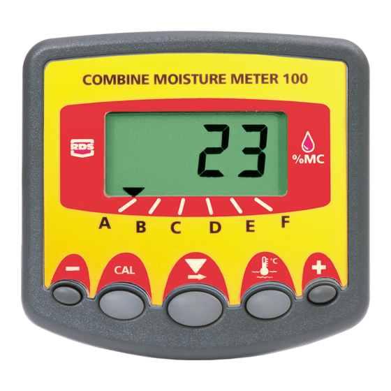
Operation The Combine Moisture Meter 100 (CMM100) is intended for use on either a combine harvester or a grain drier, and is used in conjunction with an RDS Grain Moisture Sensor to continuously monitor crop moisture content. As the grain flows over the sensor, the CMM100 provides a continuous, dynamic display of the grain moisture content, and the option to display the crop temperature at the press of a button. -
Page 5: Calibration
The CMM 100 has factory-default calibration settings for each channel A to F. These settings assume channels A to F are assigned to the following crop... -
Page 6: Operating Mode
CMM 100 : INSTALLATION, CALIBRATION AND OPERATION Operating Mode Startup On starting, the instrument should power on. If not, switch it on from the rear-mounted switch. The instrument first displays the software version installed e.g. "A.501" "E.001" "r.006" indicates software version WZ501-001 rev.06... -
Page 7: Correcting The Moisture Reading
CMM 100 : INSTALLATION, CALIBRATION AND OPERATION Correcting the Moisture Reading The grain moisture reading should be checked periodically against a reading from a reference moisture meter, particularly when combining oily or dirty crops, since the sensor can produce a false reading due to extraneous material adhering to it. -
Page 8: Excess Moisture Content Alarm (Harvesting)
CMM 100 : INSTALLATION, CALIBRATION AND OPERATION Excess Moisture Content Alarm (Harvesting) If the moisture content exceeds the preset threshold, the display flashes continuously and the alarm beeps every 30 seconds. NOTE: If fitted, the (optional) external audible alarm unit will operate in tandem with the instrument internal buzzer. -
Page 9: Set High/ Low Moisture Content Alarm Threshold
CMM 100 : INSTALLATION, CALIBRATION AND OPERATION 2.6.2 Set High/ Low Moisture Content Alarm Threshold Having first set the "HIGH / "LO" alarm option (section 2.6.1), you can then individually set the alarm threshold (% M.C.) for each channel as desired. -
Page 10: Calibration Mode
CMM 100 : INSTALLATION, CALIBRATION AND OPERATION Calibration Mode Navigating the Calibration Mode Press and hold the button as you switch the instrument on, and continue to hold for 5 seconds until the instrument enters the calibration mode. The instrument displays "CAL" then "ALAr" (for the channel last selected in Normal Operating Mode), then the current moisture alarm threshold setting (xx.xx). -
Page 11: Programming A Calibration Setting
CMM 100 : INSTALLATION, CALIBRATION AND OPERATION NOTE 1: If the operator wishes to programme the instrument for alternative crops, then they can if necessary, seek advice from either their RDS distributor or the Factory Service Department NOTE 2: The factory-default settings will be restored after a "Power-On Reset ". -
Page 12: Factor A ("A.fac") / Factor B ("B.fac")
CMM 100 : INSTALLATION, CALIBRATION AND OPERATION Factor A ("A.FAc") / Factor B ("B.FAc") May require changing if harvesting / drying crops other than the default grain types. To edit - Ref. section 3.2. Factor C ("C.FAc") This setting is the Moisture Correction Factor, required to match the moisture content reading of the instrument to that of a reference moisture meter. -
Page 13: Display Smoothing Factor
CMM 100 : INSTALLATION, CALIBRATION AND OPERATION Display Smoothing Factor This value determines how steady the moisture content display remains, when reacting to variations in moisture content during harvesting /drying A higher value (%) gives a more averaged (steadier) reading. -
Page 14: Diagnostic Mode
CMM 100 : INSTALLATION, CALIBRATION AND OPERATION Diagnostic Mode Press and hold the button as you switch the instrument on, and continue to hold for (5 seconds) until the instrument enters the diagnostic mode. The instrument displays "dIAG" and then defaults to channel A (see table 1). -
Page 15: Data Logging
CMM 100 : INSTALLATION, CALIBRATION AND OPERATION Data Logging The instrument continuously outputs a line of data every second. A 'Wizard Upload Lead' (Pt No. S/CB/327-1-030) is required, and suitable data capture software must be Connect 'Wizard installed on your PC. -
Page 16: Installation
CMM 100 : INSTALLATION, CALIBRATION AND OPERATION Installation Parts List Part No. Description S/HU/327-25-001 CMM 100 Head Unit S/AC/327-25-006 CMM 100 Terminator 2 K/INSTRUMENT Power Supply Kit K/WIZ/MTG/BKT Head Unit Mounting Kit K/ MOIST/SNR/MK4 Moisture Sensor Kit Please refer to the... - Page 17 CMM 100 : INSTALLATION, CALIBRATION AND OPERATION K//MOIST/SNR/MK4 Head Unit S/HU/327-25-001 Terminator 2 S/AC/327-25-006 Power Supply (K/INSTRUMENT)
-
Page 18: Cab Installation
CMM 100 : INSTALLATION, CALIBRATION AND OPERATION Cab Installation Requiring, S/HU/327-25-001 : Head Unit S/AC/327-25-006 : Terminator 2 K/INSTRUMENT : Power Supply Kit K/WIZ/MTG/BKT : Head Unit Mounting Kit (External Alarm optional) 6.2.1 Head Unit Confirm with the operator on where to mount the head unit in the cab. It must not restrict the view out of the cab, nor impede the use of the controls. -
Page 19: 24V Power Supply
CMM 100 : INSTALLATION, CALIBRATION AND OPERATION Snap the cover plate into the recess of the long bracket (it only fits one way). (ii) Assemble the two brackets and mounting plate with the clamping knobs, and attach to the head unit. -
Page 20: Terminator" Junction Box
CMM 100 : INSTALLATION, CALIBRATION AND OPERATION 6.2.3 "Terminator" Junction Box The "Terminator" junction box connects the head unit, moisture sensor, power supply and optional external alarm. NOTE: The Terminator is not sealed. It must be located where it will be protected... -
Page 21: Moisture Sensor Installation
CMM 100 : INSTALLATION, CALIBRATION AND OPERATION 6.2.4 Moisture Sensor Installation Requiring, K/MOIST/SNR/MK4 : Mk 4 Moisture Sensor Kit For mounting the sensor, please refer to the installation leaflet enclosed with the Moisture Sensor Kit. External Alarm An external alarm is optional. If fitting one, mount the alarm buzzer where it will stay dry. -
Page 22: Test Installation
CMM 100 : INSTALLATION, CALIBRATION AND OPERATION Test installation On starting the engine, the instrument should power on. If not, switch it on from the rear-mounted switch. The instrument first displays the software version installed e.g. "A.501" "E.001" "r.006" indicates software version WZ501-001 rev.06 The instrument then enters the Normal Operating Mode and should normally display "Ch. - Page 23 CMM 100 : INSTALLATION, CALIBRATION AND OPERATION Issue 1.1 11/4/11 Original Issue Issue 2 15/2/12 Updated for S/W Ver. WZ501-001-01 High / Low MC Alarm option for combine / drier use. Temperature Nudge. Ref. pages 3,4,5,6,7,8,9,11,12,20 Issue 3 9.11.12 Add section on serial port output...
Need help?
Do you have a question about the CMM 100 and is the answer not in the manual?
Questions and answers