Table of Contents
Advertisement
Quick Links
High Definition Video Camera
HDC-HS20P
Model No.
HDC-HS20PU
HDC-HS20EG
HDC-HS20EE
HDC-HS20EB
HDC-HS20EC
HDC-HS20EP
HDC-HS20GC
HDC-HS20GK
HDC-HS20EF
HDC-HS20GJ
HDC-HS20GN
HDC-HS20GT
HDC-HS20PC
HDC-HS20SG
HDC-HS25EB
VOL.1
Colours
(K)........Black Type
© Panasonic Corporation 2009.
Unauthorized copying and distribution is a violation
of law.
ORDER NO.VM0901011CE
B27
Advertisement
Chapters
Table of Contents

Related Manuals for Panasonic HDC-HS20P


Summary of Contents for Panasonic HDC-HS20P
- Page 1 ORDER NO.VM0901011CE High Definition Video Camera HDC-HS20P Model No. HDC-HS20PU HDC-HS20EG HDC-HS20EE HDC-HS20EB HDC-HS20EC HDC-HS20EP HDC-HS20GC HDC-HS20GK HDC-HS20EF HDC-HS20GJ HDC-HS20GN HDC-HS20GT HDC-HS20PC HDC-HS20SG HDC-HS25EB VOL.1 Colours (K)..Black Type © Panasonic Corporation 2009. Unauthorized copying and distribution is a violation of law.
-
Page 2: Table Of Contents
TABLE OF CONTENTS PAGE PAGE 1 Safety Precaution -------------------------------------------------3 1.1. General Guidelines ----------------------------------------3 2 Warning --------------------------------------------------------------4 2.1. Prevention of Electrostatic Discharge (ESD) to Electrostatic Sensitive (ES) Devices ---------------4 2.2. Service caution based on legal restrictions----------5 2.3. Caution for AC Cord (For EB/GC/SG) ----------------6 2.4. -
Page 3: Safety Precaution
1 Safety Precautions 1.1. General Guidelines 1. IMPORTANT SAFETY NOTICE There are special components used in this equipment which are important for safety. These parts are marked by in the Sche- matic Diagrams, Circuit Board Layout, Exploded Views and Replacement Parts List. It is essential that these critical parts should be replaced with manufacturer’s specified parts to prevent X-RADIATION, shock fire, or other hazards. -
Page 4: Warning
2 Warning 2.1. Prevention of Electrostatic Discharge (ESD) to Electrostatic Sensitive (ES) Devices Some semiconductor (solid state) devices can be damaged easily by static electricity. Such components commonly are called Elec- trostatic Sensitive (ES) Devices. Examples of typical ES devices are integrated circuits and some field-effect transistors and semi- conductor “chip”... -
Page 5: Service Caution Based On Legal Restrictions
2.2. Service caution based on legal restrictions 2.2.1. General description about Lead Free Solder (PbF) The lead free solder has been used in the mounting process of all electrical components on the printed circuit boards used for this equipment in considering the globally environmental conservation. The normal solder is the alloy of tin (Sn) and lead (Pb). -
Page 6: Caution For Ac Cord (For Eb/Gc
2.3.2.3. How to replace the Fuse A replacement fuse cover can be purchased from your local Panasonic Dealer. 1. Remove the Fuse Cover with a screwdriver. If the fitted moulded plug is unsuitable for the socket outlet in your home then the fuse should be removed and the plug cut off and disposed of safety. -
Page 7: How To Replace The Lithium Battery (Procedure)
2. Remove the Lithium Battery “ML-614S/ZT” and then replace the new one. (See Figure B1.) Fig. B1 Note: The lithium battery is a critical component. (Type No.: ML-614S/ZT Manufactured by Panasonic.) It must never be subjected to excessive heat or discharge. It must therefore only be fitted in equipment designed specifically for its use. -
Page 8: How To Recycle The Lithium Battery (U.s. Only)
2.5. How to Recycle the Lithium Battery (U.S. Only) -
Page 9: Service Navigation
2) The following category are recycle module part. Please send them to Central Repair Center. *Main P.C.B. (VEP03H65N: HDC-HS20P/PC/PU) (VEP03H65Q: HDC-HS20GT) (VEP03H65R: HDC-HS20EC/EF/EG) (VEP03H65S: HDC-HS20EP) (VEP03H65T: HDC-HS20EB) (VEP03H65U: HDC-HS20GC/SG) (VEP03H65V: HDC-HS20GJ) (VEP03H65W: HDC-HS20EE) (VEP03H65X: HDC-HS20GN) (VEP03H65Y: HDC-HS20GK) (VEP03H65AM: HDC-HS25EB) *Sub P.C.B. (VEP01A16B: HDC-HS20P/PC/PU/EB/EC/EE/EG/EP/GC/GK/EF/GJ/GN/GT/SG, HDC-HS25EB) -
Page 10: Service Caution
3.2. Service Caution 3.2.1. How to Discharge the Capacitor on the Sub P.C.B. Remove the Sub P.C.B.. (Refer to Disassembly Procedures.) -
Page 11: Precautions For Handling Hdd
3.3. Precautions for Handling HDD 1. Handle HDD very carefully to prevent the static electricity and shock. 2. Set the HDD quickly after taking it out from the package. Make sure to put the HDD on buffer materials, etc. 3.3.1. Precautions at incoming process and for opening packages... - Page 12 3.3.2. Precautions for installing HDD...
- Page 13 3.3.3. Precautions for inserting and removing HDD FPC Make sure to use the tool (LSVQ0112) when locking and unlocking the lock lever of HDD FPC connector. Do not lock the lock lever without inserting HDD FPC. Otherwise, the connector may be damaged.
- Page 14 Make sure to use the tool (LSVQ0112) when opening and closing the lock lever. *See "Disassembly and Assembly Instructions" (Fig. D10) for attaching to the unit.
-
Page 15: Formatting Hdd
3.4. Formatting HDD... -
Page 16: Specifications
4 Specifications... -
Page 17: Location Of Controls And Components
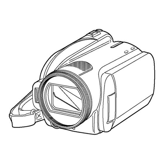
5 Location of Controls and Components Followings are the Location of Controls and Components for HDC-TM20P/PC as a sample. For other models, refer to each Operating Instructions. -
Page 22: Service Mode
6 Service Mode 6.1. Service Menu When abnormal detection contents are confirmed, do the following operation. Automatic diagnosis code will be displayed. (Service Menu) To enter the Service Menu 1. Turn the Power on and set the Mode Dial to [VIDEO RECORDING MODE]. 2. - Page 23 To select the Item of Service Menu 1. Press [TOUCH PANEL icon] to select item [1], [2], [3], [4], [5] and [6]. 2. Press [TOUCH PANEL icon] to display [YES/NO] screen. 3. Press [TOUCH PANEL icon] to select [YES]. 4. Press [TOUCH PANEL BAK] to end. Fig.
- Page 24 Fig. 1-3...
- Page 25 Fig. 1-4...
- Page 26 Fig. 1-5...
-
Page 27: About Default Setting
6.2. About Default Setting The data of Menu, Mode, Card and EEPROM setting, etc. is set to the default condition in factory. 6.2.1. How to set the Default Setting 1. Turn the Power on and set the Mode Dial to [RECORDING MODE]. 2. -
Page 28: Service Fixture & Tools
7 Service Fixture & Tools 7.1. Service Tools and Equipment... -
Page 29: Disassembly And Assembly Instructions
8 Disassembly and Assembly Instructions 8.1. Disassembly Flow Chart This flow chart indicates the disassembly steps the cabinet parts and P.C.B.. Unit in order to access to be serviced. When reinstalling, perform the steps in the reverse order. 8.2. P.C.B. Layout Fig. -
Page 30: Disassembly Procedures
8.3. Disassembly Procedures Flow-Chart for Disassembly Procedure Item / Part Fig. Removal (Screw,Connector,FPC. & Other) 10 Side (R) P.C.B. Fig. D20 2 Screws (R) Item / Part Fig. Removal (Screw,Connector,FPC. P6501 (Connector) & Other) Speaker Angle Lens Hood Fig. D2 Lens Hood Speaker Side Case (R) Unit Fig. - Page 31 Fig. D2 Fig. D4 Fig. D3...
- Page 32 Fig. D6 Fig. D5 Fig. D7...
- Page 33 Fig. D9 Fig. D8...
- Page 34 Fig. D11 Fig. D10...
- Page 35 Fig. D14 Fig. D12 Fig. D15 Fig. D13...
- Page 36 Fig. D18 Fig. D16 Fig. D17...
- Page 37 Fig. D20 Fig. D19...
- Page 38 Fig. D23 Fig. D21 Fig. D22...
- Page 39 Fig. D24 Fig. D25...
- Page 40 Fig. D26...
-
Page 41: Disassembly Procedures Of Camera Lens Unit
8.4. Disassembly Procedures of Camera Lens Unit The following flowchart describes order or steps for removing the Camera lens unit and certain printed circuit boards in order to make access to the item needing service. To reassemble the unit follow the steps in reverse order. Fig. -
Page 42: Measurements And Adjustments
9 Measurements and Adjustments 9.1. EEPROM Data for spare parts of the MAIN P.C.B. After replacing the MAIN P.C.B., be sure to achieve adjustment. The Adjustment instruction is available at “software download” on the “Support Information from NWBG/VDBG-PAVC” web-site in “TSN system”, together with Maintenance software. - Page 43 9.2.2. Checking and repairing individual circuit boards except module parts (Main P.C.B. and Sub P.C.B.) How to use extension cables.
-
Page 44: Location For Connectors Of The Main P.c.b. And Sub P.c.b
9.3. Location for Connectors of the Main P.C.B. and Sub P.C.B. 9.3.1. Main P.C.B. - Page 45 9.3.2. Sub P.C.B.
-
Page 46: Electrical Adjustment Procedures
9.4. Electrical Adjustment Procedures 9.4.1. Initial Guideline The table below shows which adjustments are necessary according to the unit parts and individual parts to be replaced. Make sure to perform these adjustments shown below as necessary. 9.4.2. Computer assisted adjustment system <TATSUJIN> adjustment This unit employs the computer assisted system named;... - Page 47 9.4.3. Set-up manual for High Definition Video Camera Pay attention, because the adjustment method is different from this machine. 1. Save the software Install the effective model’s TATSUJIN Software to PC: Personal Computer. 2. Set-Up a. It need the connection between the PC and this unit with USB cable. b.
- Page 48 9.4.4. Set up PC-EVR adjustment program 1. Turn on the PC and install the TATSUJIN Adjustment Pro- 6. Saving for EEPROM data is complete, menu will appear. gram into the PC. To perform each adjustment, display the adjustment 2. TATSUJIN PC-Adjustment Program start in the following menu by selecting the desired menu from procedure.
-
Page 49: Maintenance
10 Maintenance 10.1. Cleaning Lens and LCD Panel Do not touch the surface of the lens and LCD Panel with your hand. When cleaning the lens, use air-Blower to blow off the dust. When cleaning the LCD Panel, dampen the lens cleaning paper with lens cleaner, and the gently wipe the their surface. Note: A lens cleaning paper and lens cleaner are available at local camera shops and market place. - Page 50 3.The voltage being indicated on the schematic diagram is measured in "Standard-Playback" mode when there is no specify mode is mentioned. Model No. HDC-HS20P HDC-HS20EP 4.Although the voltage and waveform available on here is measured with standard frame, it may be differ from actual measurement due to modification of circuit and so on.
-
Page 51: S2. Voltage Chart
S2. Voltage Chart Note) Indicated voltage values are the standard values for the unit measured by the DC electronic circuit tester (high-impedance) with the chassis taken as standard. Therefore, there may exist some errors in the voltage values, depending on the internal impedance of the DC circuit tester. S2.1. -
Page 52: S3. Block Diagram
S3. Block Diagram S3.1. Overall Block Diagram IC601 COLOUR LCD PANEL LENS DATA CONTROL (CONTROLLER (LCD) INCLUDED TYPE) ZOOM/ IRIS/ FOCUS MOTOR A/V OUT IC3601 COMPONENT TERMINAL VIDEO IC101 ENCODER IC3701 AVIO IC4801, 4803 MIC AMP SPEAKER X301 IC301 IC3400 (Japan/P/PC/PL: 74.175MHz) CAMERA DSP VIDEO... -
Page 53: S4. Schematic Diagram
S4. Schematic Diagram S4.1. Interconnection Diagram FRONT ECM FPC LENS UNIT TOP/ OPERATION UNIT FP4801 ECM[L] MOS FPC UINT ECM[B] ECM[R] FP6003 LIGHT_ON_H LIGHT_ON_H OP_SHTER_LED SHTER_OPEN LENSBA_MT_B+ LENSBA_MT_B+ LENSBA_MT_B- LENSBA_MT_B- LENSBA_MT_A+ 10 LENSBA_MT_A+ 11 LENSBA_MT_A- 12 LENSBA_MT_A- 13 PW_5V 14 PW_5V 15 G_MIC_OUT_L 16 D_GND(MIC_F) 17 D_GNDMIC_C... -
Page 54: S4.2. Side R Schematic Diagram
S4.2. Side R Schematic Diagram HDC-HS20/HS25 Series Side R Section (Side R P.C.B.(1/2)) Schematic Diagram... -
Page 55: S4.3. Lcd Schematic Diagram
S4.3. LCD Schematic Diagram HDC-HS20/HS25 Series LCD Section (Side R P.C.B.(2/2)) Schematic Diagram... -
Page 56: S4.4. Front Schematic Diagram
S4.4. Front Schematic Diagram HDC-HS20/HS25 Series Front Schematic Diagram... -
Page 57: S4.5. Monitor Schematic Diagram
S4.5. Monitor Schematic Diagram HDC-HS20/HS25 Series Monitor Section (Monitor P.C.B.(1/2)) Schematic Diagram... -
Page 58: S4.6. Tpanel Schematic Diagram
S4.6. TPANEL Schematic Diagram HDC-HS20/HS25 Series TPANEL Section (Monitor P.C.B.(2/2)) Schematic Diagram... -
Page 59: S4.7. Power Fpc Schematic Diagram
S4.7. Power FPC Schematic Diagram HDC-HS20/HS25 Series Power FPC Schematic Diagram S-10... -
Page 60: S4.8. Main Sub Fpc Schematic Diagram
S4.8. Main Sub FPC Schematic Diagram HDC-HS20/HS25 Series Main Sub FPC Schematic Diagram S-11... -
Page 61: S4.9. Side R Fpc Schematic Diagram
S4.9. Side R FPC Schematic Diagram HDC-HS20/HS25 Series Side R FPC Schematic Diagram S-12... -
Page 62: S4.10. Front Fpc Schematic Diagram
S4.10. Front FPC Schematic Diagram HDC-HS20/HS25 Series Front FPC Schematic Diagram S-13... -
Page 63: S4.11. Lcd_Op Fpc Schematic Diagram
S4.11. LCD_OP FPC Schematic Diagram HDC-HS20/HS25 Series LCD_OP FPC Schematic Diagram S-14... -
Page 64: S4.12. Mos Fpc Schematic Diagram
S4.12. MOS FPC Schematic Diagram HDC-HS20/HS25 Series MOS FPC Schematic Diagram S-15... -
Page 65: S4.13. Hdd Fpc Schematic Diagram
S4.13. HDD FPC Schematic Diagram HDC-HS20/HS25 Series HDD FPC Schematic Diagram S-16... -
Page 66: S5. Print Circuit Board
S5. Print Circuit Board S5.1. Side R P.C.B. (Component Side) (Foil Side) HDC-HS20/HS25 Series Side R P.C.B. S-17... -
Page 67: S5.2. Front P.c.b
S5.2. Front P.C.B. (Component Side) (Foil Side) HDC-HS20/HS25 Series Front P.C.B. S-18... -
Page 68: S5.3. Monitor P.c.b
S5.3. Monitor P.C.B. S5.3.1. Monitor P.C.B. (Component Side) (Component Side) HDC-HS20/HS25 Series Monitor P.C.B. (Component Side) S-19... -
Page 69: S5.3.2. Monitor P.c.b. (Foil Side
S5.3.2. Monitor P.C.B. (Foil Side) (Foil Side) HDC-HS20/HS25 Series Monitor P.C.B. (Foil Side) S-20... -
Page 70: S5.4. Power Fpc P.c.b
S5.4. Power FPC P.C.B. (Component Side) (Foil Side) HDC-HS20/HS25 Series Power FPC P.C.B. S-21... -
Page 71: S5.5. Main Sub Fpc P.c.b
S5.5. Main Sub FPC P.C.B. (Component Side) (Foil Side) HDC-HS20/HS25 Series Main Sub FPC P.C.B. S-22... -
Page 72: S5.6. Side R Fpc P.c.b
S5.6. Side R FPC P.C.B. / S5.7. Front FPC P.C.B. (Foil Side) (Foil Side) HDC-HS20/HS25 Series HDC-HS20/HS25 Series Side R FPC P.C.B. Front FPC P.C.B. S-23... -
Page 73: S5.8. Lcd_Op Fpc P.c.b
S5.8. LCD_OP FPC P.C.B. (Foil Side) HDC-HS20/HS25 Series LCD_OP FPC P.C.B. S-24... -
Page 74: S5.9. Mos Fpc P.c.b
S5.9. MOS FPC P.C.B. (Component Side) (Foil Side) HDC-HS20/HS25 Series MOS FPC P.C.B. S-25... -
Page 75: S5.10. Hdd Fpc P.c.b
S5.10. HDD FPC P.C.B. S5.10.1. HDD FPC P.C.B. (Component Side) (Component Side) HDC-HS20/HS25 Series HDD FPC P.C.B. (Component Side) S-26... -
Page 76: S5.10.2. Hdd Fpc P.c.b. (Foil Side
S5.10.2. HDD FPC P.C.B. (Foil Side) (Foil Side) HDC-HS20/HS25 Series HDD FPC P.C.B. (Foil Side) S-27... - Page 77 S-28...
-
Page 78: S6. Check Point Of The Ic
S6. Check Point of The IC S6.1. Check Point of the IC601 CSP IC Check Point Remarks Name 1 SCK 2 SCS 3 SDI 4 UCONSEL 5 DIN7 6 DIN6 7 DIN5 8 DIN4 9 NC 10 DIN3 11 DIN2 12 DIN1 13 DIN0 CH602... -
Page 79: S7. Replacement Parts List
S7. Replacement Parts List Note: 1.* Be sure to make your orders of replacement parts according to this list. 2. IMPORTANT SAFETY NOTICE Components identified with the mark have the special characteristics for safety. When replacing any of these components, use only the same type. 3. - Page 80 HDC-HS20P/PC/PU/EB/EC/EE/EF/EG/EP/GC/GJ/GK/GN/GT/SG, HS25EB vol.1 Ref.No. Part No. Part Name & Description Remarks Ref.No. Part No. Part Name & Description Remarks VEP03H65N MAIN P.C.B. 1 (RTL) E.S.D.(P,PC,PU) VEP20C47A FRONT P.C.B. (RTL) E.S.D. VEP03H65T MAIN P.C.B. 1 (RTL) E.S.D.(20EB) VEP03H65R MAIN P.C.B. 1 (RTL) E.S.D.(EC,EF,EG) ...
- Page 81 HDC-HS20P/PC/PU/EB/EC/EE/EF/EG/EP/GC/GJ/GK/GN/GT/SG, HS25EB vol.1 Ref.No. Part No. Part Name & Description Remarks Ref.No. Part No. Part Name & Description Remarks VEP26321A MONITOR P.C.B. (RTL) E.S.D. VEP22399A MOS FPC (RTL) E.S.D. C501 F1G0J1050007 C.CAPACITOR CH 6.3V 1U C202 F1H0J475A010 C.CAPACITOR CH 6.3V 4.7U C502 F1G1A104A012 C.CAPACITOR CH 10V 0.1U...
- Page 82 HDC-HS20P/PC/PU/EB/EC/EE/EF/EG/EP/GC/GJ/GK/GN/GT/SG, HS25EB vol.1 Ref.No. Part No. Part Name & Description Remarks Ref.No. Part No. Part Name & Description Remarks VKM7798 SR COVER XQN16+BJ4FN SCREW VKM7804 SIDE CASE (L) XQN16+BJ4FN SCREW VYC0992 GRIP BELT VHD1411 SCREW VMP9289 BELT ANGLE (F) VHD1411...
- Page 83 HDC-HS20P/PC/PU/EB/EC/EE/EF/EG/EP/GC/GJ/GK/GN/GT/SG, HS25EB vol.1 Ref.No. Part No. Part Name & Description Remarks Ref.No. Part No. Part Name & Description Remarks VYK2X33 BOTTOM FRAME UNIT VYK2X42 LCD CASE (T) UNIT 1 (P,PC,PU,20EB,EC,EE,EF, VMP9282 LENS FRAME EG,EP,GC,GJ,GK,GN,GT,SG) VMG1107 DUMPER RUBBER VYK3F62 LCD CASE (T) UNIT...
- Page 84 HDC-HS20P/PC/PU/EB/EC/EE/EF/EG/EP/GC/GJ/GK/GN/GT/SG, HS25EB vol.1 Ref.No. Part No. Part Name & Description Remarks Ref.No. Part No. Part Name & Description Remarks VXQ1683 MOS UNIT K2GJYDC00004 DC CABLE 401-1 VEP22399A MOS FPC 1 (RTL) E.S.D. K2KYYYY00054 AV CABLE VMX3706 MOS CUSHION K1HY04YY0032 USB CABLE...
-
Page 85: S8. Exploded View
S8. Exploded View S8.1. Frame and Casing Section (1) B23 B24 S-36... -
Page 86: S8.2. Frame And Casing Section (2
S8.2. Frame and Casing Section (2) B163 B153 B166 B165 B152 B164 B167 B168 B169 B158 B157 B156 B155 B154 B161 B159 B160 S-37... -
Page 87: S8.3. Lcd Section
S8.3. LCD Section B201 215-2 B202 B203 215-1 B204 S-38... -
Page 88: S8.4. Camera Lens Section
S8.4. Camera Lens Section B401 401-1 B402 B409 B403 B404 B410 B414 B415 B413 B416 B412 B411 B406 B408 B407 B405 S-39... -
Page 89: S8.5. Packing Parts And Accessories Section
S8.5. Packing Parts and Accessories Section (GN) (P/PC/PU) 513,514 (EB/GC/SG) (GK/GT) (EC/EE/EF/EG/EP/GC/GJ/SG) Battery Pack Unit S-40...
Need help?
Do you have a question about the HDC-HS20P and is the answer not in the manual?
Questions and answers