Table of Contents
Advertisement
Quick Links
Advertisement
Chapters
Table of Contents

Subscribe to Our Youtube Channel
Related Manuals for Leica Geosystems RX1200

Summary of Contents for Leica Geosystems RX1200
- Page 1 GPS1200 User Manual Version 1.0 English...
- Page 2 The model and the serial number of your product are indicated on the type plate. tion Enter the model and serial number in your manual and always refer to this informa- tion when you need to contact your agency or Leica Geosystems authorized service workshop. Type: _______________ Serial No.:...
- Page 3 Symbols The symbols used in this manual have the following meanings: Type Description Danger Indicates an imminently hazardous situation which, if not avoided, will result in death or serious injury. Warning Indicates a potentially hazardous situation or an unintended use which, if not avoided, could result in death or serious injury.
-
Page 4: Table Of Contents
Table of Contents GPS1200 Table of Contents In this manual Chapter Page How to Use this Manual Description of the System User Interface Operation Reference Station Care and Transport Safety Directions Technical Data Index... -
Page 5: Gps1200
Table of Contents GPS1200... -
Page 6: How To Use This Manual
How to Use this Manual GPS1200 1 How to Use this Manual It is recommended to set-up the product while reading through this manual. Path Main Menu: Manage...\Data stands for this working sequence: From the Main Menu select Manage... and then select Data. Screen CONFIGURE General Menu describes the name of the screen. - Page 7 • The RX1200 is available as RX1210 or RX1220 and with touch screen function- ality as RX1210T or RX1220T. The names RX1210 and RX1220 are used throughout the manual and may also represent the T models. Only use the supplied stylus on the touch screens of the T models.
- Page 8 How to Use this Manual GPS1200 Name of docu- Description mentation GPS1200 Applica- Describes specific onboard application programs in standard tion Programs use. Intended as a quick reference field guide. Field Manual GPS1200 Tech- Overall comprehensive guide to the system and program func- nical Reference tions.
- Page 9 How to Use this Manual GPS1200...
-
Page 10: Description Of The System
Description of the System GPS1200 2 Description of the System In this chapter Topic Page System Components Container Contents Receiver Components System Concept... -
Page 11: Description Of The System Gps1200
System Components Main components Receiver: To calculate a range to all visible satellites. RX1200: To operate the user interface either by the keyboard or by the touch screen with supplied stylus. Antenna: To receive the satellite signals from the NAVSTAR satellites. - Page 12 Description of the System GPS1200 GRX1200 Pro Twelve L1, twelve L2 channels, code and phase, real-time capable, with event, PPS, oscillator and NET port, for reference station applications Refer to "8 Technical Data" for information on technical specifications. The GX1230, GX1220, GX1200 with PPS/Event option, GRX1200 and GRX1200 Pro receivers use the GPS P-code signal, which by U.S.
- Page 13 • to exchange data between the • to load and delete system software receiver and a PC. and application program software. Operating systems • Windows® XP • Windows® ME • Windows® 2000 Refer to the online help of LGO for additional information. Leica GPS Spider The reference station software is known as Leica GPS Spider.
-
Page 14: Container Contents
Description of the System GPS1200 Container Contents Description The GPS1200 with all accessories is packed in one transport container. Additional equipment which does not fit into the transport container might be required, for example a tripod. These accessories are not mentioned. - Page 15 Lower portion a) Double arm for antennas of devices b) Adjusting pin c) Spare battery d) Supplied stylus e) Antennas of device GX1200 with RX1210 and device such as radio g) Antenna h) Cables GPS12_135 Description of the System GPS1200...
- Page 16 Description of the System GPS1200 Upper portion a) Base for telescopic rod b) Holder for RX1210 on pole with grip for pole c) Spare battery d) Arm 15 cm long for antenna of device e) Telescopic rod Holder for GX1200 on pole g) Tribrach h) Carrier Height hook...
-
Page 17: Receiver Components
The receiver can be preprogrammed in the office and used in the field without the RX1200 attached. In this case, the receiver is turned on by holding down the ON/OFF button for 2 s or off by holding down the ON/OFF button for 4 s. A green steady light at the power LED indicates that the receiver is turned on. -
Page 18: System Concept
Description of the System GPS1200 System Concept In this chapter Topic Page 2.4.1 Software Concept 2-10 2.4.2 Data Storage and Data Conversion 2-12 2.4.3 Power 2-14... -
Page 19: Software Concept
Customised application programs can be developed locally using the GeoC++ cation programs development environment. Information on the GeoC++ development environment is available on request from the Leica Geosystems representative. Languages Number of languages: Three languages can be stored on the receiver at one time - English and two others. - Page 20 Description of the System GPS1200 2-11 Validity of a language: • For standard software: If a language is not available for the system software, the English language is used instead. Application programs run in the language they where loaded. • Customised application programs do always run in the language they were developed in.
-
Page 21: Data Storage And Data Conversion
2.4.2 Data Storage and Data Conversion Description Data is stored within a job in a database on a memory device. This is either a CompactFlash card or an internal memory. Memory device CompactFlash card: A CompactFlash card slot is standard. A CompactFlash card can be inserted and removed. - Page 22 • From the CompactFlash card using for example an OMNI drive as supplied by Leica Geosystems to a project in LGO on a PC. CompactFlash cards can directly be used in an OMNI drive as supplied by Leica Geosystems. Other PC card drives may require an adaptor.
-
Page 23: Power
Power General Use the Leica Geosystems batteries, chargers and accessories or accessories recommended by Leica Geosystems to ensure the correct functionality of the instru- ment. Description Power for the receiver can be supplied either internally or externally. Up to two external power supplies can be connected using a Y-cable. - Page 24 Description of the System GPS1200 2-15 For permanent operations use Uninterruptible Power Supply units as a back-up in case of a main power failure.
- Page 25 Description of the System GPS1200 2-16...
-
Page 26: User Interface
User Interface GPS1200 3 User Interface In this chapter Topic Page General Operating Principles Icons... - Page 27 General Operating Principles Keyboard and The user interface is operated either by the keyboard or by the touch screen with touch screen supplied stylus. The workflow is the same for keyboard and touch screen. The difference is the way information is selected and entered. Selecting from a Appearance Description...
- Page 28 User Interface GPS1200 Closed choicelist Appearance Description Selection Triangles on the right indi- Use the arrow keys cate further available to toggle through the list or choices. tap the triangles on the screen. ENTER or tap on the field to access the choicelist. Opening a choicelist reveals either a simple listbox or a comprehensive listbox dialogue.
- Page 29 Listbox dialogue Appearance Description Selection • Choicelist fills the • Highlight an item and whole screen. CONT (F1) or ENTER. • A search field is • To exit without shown. changes press ESC or tap . • A scroll bar is shown if necessary.
- Page 30 User Interface GPS1200 Icons Description Icons show the current status information of the receiver. The icons provide information related to basic receiver functions. The icons that appear depend upon which GPS1200 receiver is used and the current receiver configuration. Position of the b c d e f g h i icons on the screen...
- Page 31 Icons Icon Description Position status Displays the status of the current position. As soon as this icon becomes visible the receiver is in a stage where practical operation can commence. Number of visible Displays the number of theoretically visible satellites above satellites the configured cut off angle according to the current almanac.
- Page 32 User Interface GPS1200 Icon Description Quick coding The Quick coding is displayed. Visible during Survey and other application programs where it is possible to measure a point with quick codes. Line/area The number of lines and areas currently open in the active job is displayed.
- Page 33 Icon Description • If two external power supplies are attached, then the system uses the one which is configured as the preferred power supply. SHIFT The status of the SHIFT key is displayed. User Interface GPS1200...
-
Page 34: Operation
Operation GPS1200 4 Operation In this chapter Topic Page Equipment Setup Battery CompactFlash Card Clip-On-Housings for Devices 4-11 Accessing Survey Application Program 4-20 Guidelines for Correct Results 4-23 Operation with a Typical Configuration Set 4-24... -
Page 35: Equipment Setup
Equipment Setup The example given is for static operations. Equipment setup Step Description step-by-step Set up the tripod. Mount and level the tribrach on the tripod. Ensure that the tribrach is over the marker. Place and lock the carrier in the tribrach. Screw the GPS antenna onto the carrier. - Page 36 Close the lid carefully after insertion of the CompactFlash card in order to prevent water and dust from getting inside the receiver. Attach the RX1200 to the receiver, if required, either directly or via a connection cable by plugging it into the port RX on the receiver.
-
Page 37: Battery
Battery Change battery The batteries are inserted in the front of the receiver. step-by-step GPS12_085 Step Description Loosen the screw of one of the battery compartments. Open the cover of the battery compartment. With the Leica logo facing upwards, slide the battery into the battery compartment and push upwards so that it locks into position. - Page 38 Operation GPS1200 Step Description Close the cover of the battery compartment and tighten the screw. Repeat steps 2. to 4. for the second battery compartment. To remove a battery, loosen the screw to open the cover of the battery compartment. Push the battery slightly in and at the same time downwards.
- Page 39 +10°C to +20°C/+50°F to +68°F if possible. • It is normal for the battery to become warm during charging. Using the chargers recommended by Leica Geosystems, it is not possible to charge the battery if the temperature is too high. Operation/Discharging •...
-
Page 40: Compactflash Card
Operation GPS1200 CompactFlash Card • Keep the card dry. • Use it only within the specified temperature range. • Do not bend the card. • Protect the card from direct impacts. Failure to follow these instructions could result in data loss and/or permanent damage to the card. - Page 41 Battery compartment A GPS12_086 Step Description Loosen the screw of the battery compartment A. Open the cover of battery compartment A. The card should be held with the lable for the care instructions towards the right-hand side of the receiver. Slide the card firmly into the slot until it clicks into position.
- Page 42 Operation GPS1200 Step Description Pull out the CompactFlash card. Close the compartment cover. Format a Compact- Formatting the CompactFlash card before logging data is started is required if a Flash card step-by- completely new CompactFlash card is used or if all existing data needs to be step deleted.
- Page 43 Step Description To exit the screen without formatting the memory device, press ESC. This returns to the previous screen. CONT (F1) YES (F4) to continue with the formatting of the selected device. NO (F6) to not continue with the formatting of the selected device and to return to TOOLS Format Memory Device.
-
Page 44: Clip-On-Housings For Devices
Operation GPS1200 4-11 Clip-On-Housings for Devices Devices fitting into Digital cellular phones fitting into a clip-on-housing a clip-on-housing Digital cellular phone Clip-on-housing Ericsson DM25 GFU18 Siemens MC45 GFU17 Radios fitting into a clip-on-housing Radio Clip-on-housing Pacific Crest PDL, receive GFU15 Satelline 3AS, transceive GFU14 Attach a clip-on-... - Page 45 Step Description Ensure that the connector on the clip-on-housing fits to port P1 or port P3 on the receiver front panel. Slide the clip-on-housing towards the receiver front panel until the connector is completely plugged into port P1 or port P3. On the top side of the clip-on-housing, turn the screw clockwise, as shown by the symbols on the screw, to lock the clip-on-housing to the receiver.
- Page 46 Operation GPS1200 4-13 Step Description Locate the SIM card screw, that covers the SIM card slot, on the bottom of the clip-on-housing. Insert the coin into the groove of the SIM card screw. Turn the coin anticlockwise to loosen the SIM card screw. Remove the SIM card screw from the housing.
- Page 47 GPS12_088 Step Description Take a coin and a pen. Locate the SIM card screw, that covers the SIM card slot, on the bottom of the clip-on-housing. Insert the coin into the groove of the SIM card screw. Turn the coin anticlockwise to loosen the SIM card screw. Operation GPS1200 4-14...
- Page 48 Operation GPS1200 4-15 Step Description Remove the SIM card screw from the housing. Using the pen, press the small button of the SIM card slot to eject the SIM card holder. Take the SIM card holder out off the SIM card slot. Take the SIM card out of the SIM card holder.
- Page 49 Diagram a) Warning LED, available for Satelline b) Data transfer LED c) Signal strength LED or Status LED for Bluetooth communication module d) Power LED GPS12_089 Operation GPS1200 4-16...
- Page 50 Operation GPS1200 4-17 Description of the LED’s IF the THEN Warning GFU14 with the device is in the configuration Satelline 3AS mode controlled from the PC via cable. Data any device data not being transferred. transfer green or flashing data is being transferred. green...
- Page 51 IF the THEN Signal GFU18 with call is in progress. strength Ericsson DM25 no call is in progress or device is off. GFU17 with call is in progress. Siemens MC45 red: long flash, no SIM card inserted, no PIN short break entered or network search, user authentication or network login in progress.
- Page 52 Operation GPS1200 4-19 IF the THEN GFU15 with red or flashing red the communication link, Data Pacific Crest Carrier Detection, is okay on the roving receiver. the DCD is not okay. GFU14 with red or flashing red the communication link, Data Satelline 3AS Carrier Detection, is okay on the roving receiver.
-
Page 53: Accessing Survey Application Program
Accessing Survey Application Program Access Select Main Menu: Survey. Press PROG. Highlight Survey. CONT (F1). SURVEY Survey Begin CONT (F1) To accept changes and access the subsequent screen. The chosen settings become active. CONF (F2) Available for <R-Time Mode: None> and <R-Time Mode: Rover>. - Page 54 Operation GPS1200 4-21 Description of fields Field Option Description <Job:> Choicelist The active job. All jobs from Main Menu: Manage...\Jobs can be selected. <Coord Output The coordinate system currently attached to the System:> selected <Job:>. <Codelist:> Choicelist No codes are stored in the selected <Job:>. All codelists from Main Menu: Manage...\Codelists can be selected.
- Page 55 Field Option Description The receiver has numerous user configurable parameters and functions. This allows a variety of preferences to be addressed. The configura- tion of the parameters and functions for an indi- vidual measuring technique are combined in a configuration set. <Antenna:>...
-
Page 56: Guidelines For Correct Results
Operation GPS1200 4-23 Guidelines for Correct Results Undisturbed satel- Successful GPS surveys require undisturbed satellite signal reception, especially at lite signal recep- the receiver which serves as a reference. Set up the receivers in locations which are tion free of obstructions such as trees, buildings or mountains. Steady antenna for For static surveys, the antenna must be kept perfectly steady throughout the whole static surveys... -
Page 57: Operation With A Typical Configuration Set
Operation with a Typical Configuration Set The example given is for static operations. Static operations Step Description step-by-step Set up the equipment. Always fill out a field record sheet for each point. It is vital that the antenna height is measured correctly. Measure the height at the beginning and at the end of the occupation. - Page 58 Operation GPS1200 4-25 Step Description SURVEY Survey: Job Name Type in the point ID and the antenna height. The position mode icon is the moving icon. This indicates that the antenna can be moved around and that no static observations are being recorded. OCUPY (F1) starts logging of static observations.
- Page 59 Step Description Measure the antenna height and note it down in the field record sheet. If the tribrach is not level or the antenna height has changed, the collected data is not reliable. SHIFT QUIT (F6) to return to from where SURVEY Survey: Job Name was accessed.
- Page 60 Operation GPS1200 4-27 The antenna must not be moved while data is logged, otherwise the quality of post- processed coordinates is impaired. The CompactFlash card must be removed in GPS1200 Main Menu. If the card is removed when in any other screen all stored data might get corrupted, preventing LGO from successfully reading the data on the card.
- Page 61 Operation GPS1200 4-28...
-
Page 62: Reference Station
Reference Station GPS1200 5 Reference Station In this chapter Topic Page Overview Equipment Setup Getting Started with the GRX1200/GRX1200 Pro 5-10... - Page 63 Overview Description The GRX1200/GRX1200 Pro • are designed to operate for specific reference station applications using remote control software, for example Leica GPS Spider reference station software. • support internal logging of raw observations which can be downloaded using an external remote control software package such as Leica GPS Spider.
- Page 64 One port for input from an external oscillator Data storage All CompactFlash cards recommended by Leica Geosystems are supported. Storing data on a CompactFlash card enables subsequent data download and post- processing. Refer to "2.4.2 Data Storage and Data Conversion" for information on available memory.
- Page 65 Special commands from Outside World Interface or Leica Binary 2 format can be remote control used to control the receiver through the configured port. Documentation for OWI and LB2 is available on request from the Leica Geosystems representative. Reference Station GPS1200...
- Page 66 Reference Station GPS1200 Equipment Setup Equipment setup An example for an equipment setup for a reference station is shown in the following diagram. It is a basic serial setup with Leica GPS Spider, including a meteo/tilt device and a local radio to broadcast real-time data.
- Page 67 GPS12_027 Reference Station GPS1200...
- Page 68 Reference Station GPS1200 a) Power supply unit 100/240 V AC to k) CompactFlash card 12 V DC b) Interface cable Radio interface cable c) DB9 surge arrester with 12 V DC m) Radio pass through d) Meteo/tilt device with interface cable n) Cable to connect radio antenna e) Receiver GRX1200/GRX1200 Pro o) PC with, for example, Leica GPS Spider...
- Page 69 Unauthorised radio units should not be connected to the GRX1200/GRX1200 Pro. Cable connection Cable connections are identical to other GPS1200 receivers. Additional cables are available from Leica Geosystems for the specific oscillator and Ethernet ports on the GRX1200 Pro. Switch on Hold down the ON/OFF button on the receiver for at least 2 s.
- Page 70 Reference Station GPS1200 Behaviour when Turning the GRX1200/GRX1200 Pro off and on again resets the receiver. The turning off and on consequences are: • If the configuration of the output is stored in the configuration set, standard NMEA messages are still output. •...
- Page 71 Getting Started with the GRX1200/GRX1200 Pro Ways of operating The GRX1200/GRX1200 Pro can either be operated with the RX1200 like the other GPS1200 receivers or by remote control. Operation Description With RX1200 The receiver can be fully configured. In order to start and stop...
- Page 72 Reference Station GPS1200 5-11 Operation Description Any application program available on GPS1200 such as Survey or Stakeout Refer to the relevant chapters in this manual or to the GPS1200 Technical Reference Manual for infor- mation on configuring and using the receiver. By remote control •...
- Page 73 Data bits: 8 Parity: None Stop bit: 1 Flow control: None Specific devices such as modems for a Must be configured using the RX1200. particular port Refer to "Configure a modem interface step-by-step" for an example. GRX1200 Pro built-in ethernet device for Must be configured using the RX1200.
- Page 74 Reference Station GPS1200 5-13 Remote interface to be configured Configure using Any other interface and operation config- Can be done using Leica GPS Spider. uration required Configure a In order to use a modem for the remote interface connection, the corresponding modem interface device has to be created on the receiver and attached to the receiver serial port.
- Page 75 Step Description CONFIGURE Devices, Modem/GSM page Highlight Modem. NEW (F2) to create a new modem. CONFIGURE Device Type in a name and the port parameters for the modem. ATCMD (F4) to configure the communication commands for the modem. CONT (F1) to return to CONFIGURE Devices, Modem/GSM page. The receiver is ready to accept an incoming call from a remote application.
- Page 76 Reference Station GPS1200 5-15 remote interface to it. Refer to the GPS1200 Technical Reference Manual for more information. Step Description Main Menu: Config...\Instrument Settings...\Set NET Parameters CONFIGURE Set NET Parameters Enter the Internet Protocol address and network mask. CONT (F1) returns to GPS1200 Main Menu. Main Menu: Config...\Interfaces...
- Page 77 Step Description USE (F6) to use the port NET by remote. Press CONT (F1) twice to return to GPS1200 Main Menu. The receiver is ready to accept an incoming call from a remote application. Connect the receiver port NET to a LAN using a suitable network cable. Reference Station GPS1200 5-16...
-
Page 78: Care And Transport
Care and Transport GPS1200 6 Care and Transport In this chapter Topic Page Transport Storage Cleaning and Drying... - Page 79 Always carry the product in its transport container and secure it. Shipping When transporting the product by rail, air or sea, always use the complete original Leica Geosystems packaging, transport container and cardboard box, or its equiva- lent, to protect against shock and vibration. Shipping, transport...
- Page 80 Care and Transport GPS1200 Storage Product Respect the temperature limits when storing the equipment, particularly in summer if the equipment is inside a vehicle. Refer to "8 Technical Data" for information about temperature limits. Li-Ion batteries • Refer to "8.3 General Technical Data of the Receiver" for information about storage temperature range.
- Page 81 Cleaning and Drying Product Use only a clean, soft, lint-free cloth for cleaning. If necessary, moisten the cloth with water or pure alcohol. Do not use other liquids; these may attack the polymer components. Damp products Dry the product, the transport container, the foam inserts and the accessories at a temperature not greater than 40°C/108°F and clean them.
-
Page 82: Safety Directions
Safety Directions GPS1200 7 Safety Directions In this chapter Topic Page General Intended Use Limits of Use Responsibilities Software Licence Agreement Hazards of Use Electromagnetic Compatibility EMC 7-18 FCC Statement, Applicable in U.S. 7-21... - Page 83 General Description The following directions should enable the person responsible for the product, and the person who actually uses the equipment, to anticipate and avoid operational hazards. The person responsible for the product must ensure that all users understand these directions and adhere to them.
- Page 84 • Modification or conversion of the product. • Use after misappropriation. • Use of products with obviously recognizable damages or defects. • Use with accessories from other manufacturers without the prior explicit approval of Leica Geosystems.
- Page 85 • Inadequate safeguards at the surveying site, for example when measuring on roads. • Controlling of machines, moving objects or similar monitoring application without additional control- and safety installations. Warning Adverse use can lead to injury, malfunction and damage. It is the task of the person responsible for the equipment to inform the user about hazards and how to counteract them.
- Page 86 Safety Directions GPS1200 Limits of Use Environment Suitable for use in an atmosphere appropriate for permanent human habitation: not suitable for use in aggressive or explosive environments. Danger Local safety authorities and safety experts must be contacted before working in hazardous explosive areas, or in close proximity to electrical installations or similar situations by the person in charge of the product.
- Page 87 Geosystems, is responsible for supplying the product, including the user manual and original accessories, in a completely safe condition. Manufacturers of The manufacturers of non Leica Geosystems accessories for the product are non Leica Geosys- responsible for developing, implementing and communicating safety concepts for...
- Page 88 Leica Geosystems. Such software is protected by copy- right and other laws and its use is defined and regulated by the Leica Geosystems Software Licence Agreement, which covers aspects such as, but not limited to, Scope of the Licence, Warranty, Intellectual Property Rights, Limitation of Liability, Exclusion of other Assurances, Governing Law and Place of Jurisdiction.
- Page 89 nying documentation and the purchase receipt to the dealer from whom you purchased the product within ten (10) days of purchase to obtain a full refund of the purchase price. Safety Directions GPS1200...
- Page 90 Safety Directions GPS1200 Hazards of Use Warning The absence of instruction, or the inadequate imparting of instruction, can lead to incorrect or adverse use, and can give rise to accidents with far-reaching human, material, financial and environmental consequences. Precautions: All users must follow the safety directions given by the manufacturer and the direc- tions of the person responsible for the product.
- Page 91 Danger Because of the risk of electrocution, it is very dangerous to use poles and extensions in the vicinity of electrical installations such as power cables or electrical railways. Precautions: Keep at a safe distance from electrical installations. If it is essential to work in this environment, first contact the safety authorities responsible for the electrical instal- lations and follow their instructions.
- Page 92 Precautions: Adhere to the instructions given by the computer manufacturer with regard to field use in conjunction with Leica Geosystems products. Caution If the accessories used with the product are not properly secured and the product is subjected to mechanical shock, for example blows or falling, the product may be damaged or people may sustain injury.
- Page 93 Before transportation or shipping contact your local passenger or freight transport company. Warning Using a battery charger not recommended by Leica Geosystems can destroy the batteries. This can cause fire or explosions. Precautions: Only use chargers recommended by Leica Geosystems to charge the batteries.
- Page 94 Safety Directions GPS1200 7-13 Warning High mechanical stress, high ambient temperatures or immersion into fluids can cause leackage, fire or explosions of the batteries. Precautions: Protect the batteries from mechanical influences and high ambient temperatures. Do not drop or immerse batteries into fluids. Warning Short circuited battery terminals can overheat and cause injury or fire, for example by storing or transporting in pockets if battery terminals come in contact with jewel-...
- Page 95 • If polymer parts are burnt, poisonous gas are produced which may impair health. • If batteries are damaged or are heated strongly, they can explode and cause poisoning, burning, corrosion or environmental contamination. • By disposing of the product irresponsibly you may enable unauthorized persons to use it in contravention of the regulations, exposing themselves and third parties to the risk of severe injury and rendering the environment liable to contamination.
- Page 96 Safety Directions GPS1200 7-15 in such an environment contact the safety authorities responsible for electrical installations and follow their instructions. • If the product has to be permanently mounted in an exposed location, it is advis- able to provide a lightning conductor system. A suggestion on how to design a lightning conductor for the product is given below.
- Page 97 The air terminal diameter should be 12 mm for copper or 15 mm for aluminium. The height of the air terminals should be 25 cm to 50 cm. All air terminals should be connected to the down conductors. The diameter of the air terminal should be kept to a minimum to reduce GPS signal shading.
- Page 98 Safety Directions GPS1200 7-17 Grounding the receiver/antenna a) Lightning conductor array b) GPS antenna c) Antenna/receiver connection d) Metallic mast e) Connection to earth GPS12_060...
- Page 99 Warning Electromagnetic radiation can cause disturbances in other equipment. Although the product meets the strict regulations and standards which are in force in this respect, Leica Geosystems cannot completely exclude the possibility that other equipment may be disturbed. Caution There is a risk that disturbances may be caused in other equipment if the product is...
- Page 100 Although the product meets the strict regulations and standards which are in force in this respect, Leica Geosystems cannot completely exclude the possibility that the product may be disturbed by very intense electromagnetic radiation, for example, near radio transmitters, two-way radios or diesel generators.
- Page 101 Although the product meets in combination with radio or digital cellular phone devices recommended by Leica Geosystems the strict regulations and standards which are in force in this respect, Leica Geosystems cannot completely exclude the possibility that other equipment may be disturbed or that humans or animals may be affected.
- Page 102 Safety Directions GPS1200 7-21 FCC Statement, Applicable in U.S. Applicability The grayed paragraph below is only applicable for products of the GPS1200 system without radio or digital cellular phone devices. Warning This equipment has been tested and found to comply with the limits for a Class B digital device, pursuant to part 15 of the FCC rules.
- Page 103 Warning Changes or modifications not expressly approved by Leica Geosystems for compli- ance could void the user's authority to operate the equipment. Labelling GPS1200 Type: GX........
- Page 104 Safety Directions GPS1200 7-23 Labelling RX1200 This device complies with Type: RX.... part 15 of the FCC Rules....Operation is subject to the .
- Page 105 Labelling GFU17 Type: GFU17 ..........
- Page 106 Safety Directions GPS1200 7-25 Labelling internal battery GEB211, GEB221 This device complies with part 15 of the FCC Rules. Operation is subject to the following two conditions: (1) This device may not cause harmful interference, and (2) this device must accept any interference received, including interference that may cause undesired operation.
- Page 107 Safety Directions GPS1200 7-26...
- Page 108 Technical Data GPS1200 8 Technical Data In this chapter Topic Page Tracking Characteristics of the Receiver Accuracy General Technical Data of the Receiver Antennas 8-13 RX1210 8-18 Bluetooth Device and Digital Cellular Phones 8-20...
- Page 109 Tracking Characteristics of the Receiver GPS technology SmartTrack Satellite reception GX1230/GX1220/GRX1200/GRX1200 Pro: Dual frequency GX1210: Single frequency Receiver channels GX1230/GX1220/GRX1200/GRX1200 Pro: Twelve channels continuous tracking on L1 and L2 GX1210: Twelve channels continuous tracking on L1 Supported codes Type GX1230/GX1220/ Carrier phase, C/A code Carrier phase, P2 code GRX1200/...
- Page 110 Technical Data GPS1200 Carrier tracking Condition GX1230/GX1220/GRX1200/ GX1210 GRX1200 Pro L1, AS off or on Reconstructed carrier phase Reconstructed carrier phase via C/A code via C/A code L2, AS off Reconstructed carrier phase via P2 code L2, AS on Switches automatically to patented P code-aided tech- nique providing full L2 recon- structed carrier phase...
- Page 111 Condition GX1230/GX1220/GRX1200/ GX1210 GRX1200 Pro L2, AS on Carrier phase smoothed code measurements: Patented P code-aided code Carrier phase and code measurements on L1 and L2 are fully independent with AS on or off. Satellites tracked GX1230/GX1220/GRX1200/GRX1200 Pro: Up to twelve simultaneously on L1 and L2 GX1210: Up to twelve simultaneously on L1...
- Page 112 Technical Data GPS1200 Accuracy Accuracy is dependent upon various factors including the number of satellites tracked, constellation geometry, observation time, ephemeris accuracy, ionospheric disturbance, multipath and resolved ambiguities. The following accuracies, given as root mean square, are based on measurements processed using LGO and on real-time measurements.
- Page 113 Long baselines with GX1230/GX1220/GRX1200/GRX1200 Pro plus AT504 Static Horizontal Vertical 3 mm + 0.5 ppm 6 mm + 1 ppm Short baselines with GX1210 plus AX1201 Static Kinematic Horizontal Vertical 10 mm + 1 ppm 20 mm + 2 ppm 20 mm + 2 ppm Differential phase GX1230/GX1220/GRX1200/GRX1200 Pro plus AX1202...
- Page 114 Technical Data GPS1200 General Technical Data of the Receiver Dimensions The dimensions are given for the housing without the sockets. Type Length [m] Width [m] Thickness [m] All receivers 0.212 0.166 0.079 Weight Receiver weights without battery and radio: Type Weight [kg] GX1230/GX1220/GX1210/GRX1200 GRX1200 Pro...
- Page 115 Operating times The given operating times are valid for • all receiver types except GRX1200 Pro. • receiver plus antenna plus RX1200 without keyboard illumination and without screen heating. • two fully charged GEB221 batteries. • room temperature. Operating times will be shorter when working in cold weather.
-
Page 116: Technical Data
Technical Data GPS1200 Equipment Operating time Type Radio Digital cellular phone Static 15 h continuously Rover Pacific Crest PDL, 10 h continuously receive Rover Siemens MC45 10 h continuously Environmental Temperature specifications Type Operating temperature [°C] Storage temperature [°C] GX1230/GX1220/ -40 to +65 -40 to +80 GX1210/GRX1200... - Page 117 Type Operating temperature [°C] Storage temperature [°C] Battery internal -20 to +55 -40 to +70 Protection against water, dust and sand Type Protection All receivers IP67 (IEC 60529) Dusttight Waterproof to 1 m temporary immersion Humidity Type Protection All receivers Up to 100 % The effects of condensation are to be effectively counter- acted by periodically drying out the receiver.
- Page 118 Impedance: Pulse length: 1 ms Leading edge: Coinciding with the beginning of each epoch. Positive/negative edge: Selectable via RX1200. Cable connectivity: Matched with an appropriate impedance of: 50 Ω Connector type: Huber & Suhner FFA.0S.CTAC32Z Event input For GX1200 with PPS/Event option and GRX1200 Pro...
- Page 119 External oscillator For GRX1200 Pro input External clock input: Frequency: 5 MHz or 10 MHz 50 Ω nominal Input impedance: Input VSWR: 2:1 maximum Signal level: 0 dBm minimum to +13.0 dBm maximum Frequency stability: ±0.5 ppm maximum Wave shape: Sinusoidal Connector: MMCX female...
- Page 120 Technical Data GPS1200 8-13 Antennas Description and The GPS antenna is selected for use based upon the application. The table gives a description and the intended use of the individual antennas. Type Description AX1201 L1 SmartTrack antenna with built With GX1210 receiver. in groundplane.
- Page 121 Connector AX1201/AX1202: TNC female AT504: N female Mounting AX1201/AX1202/AT504: 5/8" Whitworth Weight AX1201/AX1202: 0.44 kg AT504 4.3 kg, radome 1.1 kg Electrical data Type AX1201 AX1202 AT504 Voltage 4.75 to 15 V DC 4.75 to 15 V DC 4.75 to 15 V DC Current 50 mA max 50 mA max...
- Page 122 Technical Data GPS1200 8-15 Type AX1201 AX1202 AT504 BW, -30 dBi 120 MHz max Environmental Temperature specifications Type Operating temperature [°C] Storage temperature [°C] All antennas -40 to +70 -40 to +70 Protection against water, dust and sand Type Protection AX1201/AX1202 IP66, IP67 (IEC 60529) Dusttight...
- Page 123 Humidity Type Protection AX1201/AX1202 Up to 100 % The effects of condensation are to be effectively counter- acted by periodically drying out the antenna. AT504 Up to 92 % The effects of condensation are to be effectively counter- acted by periodically drying out the antenna. Cable length Separation distance to antenna...
- Page 124 Technical Data GPS1200 8-17 Separation distance to antenna Supplied Optional from receiver ... cable lengths cable lengths GRX1200 Pro AT504/AX1202...
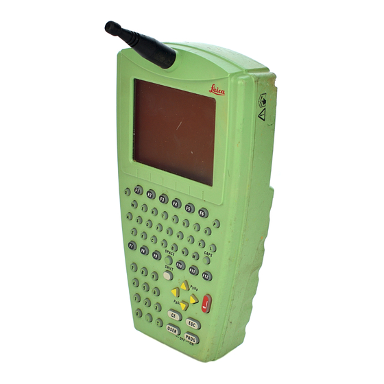
- Page 125 RX1210 Control unit Display: 1/4 VGA, monochrome, graphics capable Keyboard: 62 keys; 12 function keys, illumination Characters: Maximum 256, extended ASCII character set as standard Touch screen Toughened film on glass Dimensions Type Length [m] Width [m] Thickness [m] RX1210 0.218 0.123 0.036...
- Page 126 Technical Data GPS1200 8-19 Protection against water, dust and sand Type Protection RX1210 IP67 (IEC 60529) Dusttight Waterproof to 1 m temporary immersion Humidity Type Protection RX1210 Up to 100 % The effects of condensation are to be effectively counter- acted by periodically drying out the RX1210.
- Page 127 Bluetooth Communication Module and Digital Cellular Phones In this chapter Topic Page 8.6.1 GFU16, Bluetooth communication module 8-21 8.6.2 GFU17, Siemens MC45 8-22 8.6.3 GFU18, TDMA cellular phone Ericsson DM25 8-24 Technical Data GPS1200 8-20...
- Page 128 Technical Data GPS1200 8-21 8.6.1 GFU16, Bluetooth communication module Conformity to • FCC Part 15 (applicable in US) national regula- • European Directive 1999/5/EC on radio equipment and telecommunication tions terminal equipment (see CE Conformity Declaration) • The conformity for countries with other national regulations not covered by the FCC part 15 or European directive 1999/5/EC has to be approved prior to use and operation.
- Page 129 8.6.2 GFU17, Siemens MC45 Conformity to • FCC Part 15 and 24 (applicable in US) national regula- • European Directive 1999/5/EC on radio equipment and telecommunication tions terminal equipment (see CE Conformity Declaration) • The conformity for countries with other national regulations not covered by the FCC part 15 and 24 or European directive 1999/5/EC has to be approved prior to use and operation.
- Page 130 Technical Data GPS1200 8-23 Specific Absorp- The product meets the limits for the maximum permissible exposure of the guide- tion Rate (SAR) lines and standards which are force in this respect. The product must be used with the recommended antenna. A separation distance of at least 20 centimeters should be kept between the antenna and the body of the user or nearby person within the intended application.
- Page 131 8.6.3 GFU18, TDMA cellular phone Ericsson DM25 Conformity to • FCC Part 15, 22 and 24 (applicable in US) national regula- • European Directive 1999/5/EC on radio equipment and telecommunication tions terminal equipment (see CE Conformity Declaration) • The conformity for countries with other national regulations not covered by the FCC part 15, 22 and 24 or European directive 1999/5/EC has to be approved prior to use and operation.
- Page 132 Technical Data GPS1200 8-25 Specific Absorp- The product meets the limits for the maximum permissible exposure of the guide- tion Rate (SAR) lines and standards which are force in this respect. The product must be used with the recommended antenna. A separation distance of at least 20 centimeters should be kept between the antenna and the body of the user or nearby person within the intended application.
- Page 133 Technical Data GPS1200 8-26...
-
Page 134: Index
Index GPS1200 Index For internal power supply ......2-14 Icon ............... 3-7 AC, power supply unit ........2-14 Internal ............8-8 In Diagram .............5-7 Baud rate ............5-12 Accuracy .............8-5 Bluetooth communication module ....8-21 Antennas ............8-13 GFU16 Bluetooth communication module ..8-21 GFU17, Siemens MC45 ......8-22 Capacity, memory .......... -
Page 135: Gps1200
Memory device ..........2-12 Device Remove ............4-7 Clip-on-housing ........... 4-11 Safety instructions .........4-7 Status ............4-15 Connector, antennas ........8-14 Dimensions Container Antennas ............. 8-13 Contents ............2-5 Receivers ............8-7 Lower portion ..........2-6 RX1210 ............8-18 Upper portion ..........2-7 Documentation ........... 1-2 Contents, container ..........2-5 Drive Conversion of data ...........2-13... -
Page 136: Gps1200
Index GPS1200 Event input ............8-11 Exchange data Housing for devices ......... 4-11 Between receiver and PC ......2-4 External power supply ........2-14 Icons ..............3-6 Indicators, LED ..........4-15 Fields ..............1-1 Insert Flashing LED on clip-on-housing .....4-18 CompactFlash card ........4-7 Flow control ............5-12 SIM card ............. - Page 137 Housing ............4-15 Leica NiCd battery ............8-8 Geo Office ..........2-2, 2-3 GPS Spider ..........2-2, 2-4 OFF button ..........2-8, 4-3 LGO ..............2-3 OMNI drive ............2-13 Light Emitting Diode .........4-15 ON button ............ 2-8, 4-3 Li-Ion battery ............8-8 Operating times ..........8-8 Storage ............6-3 Operation Line, icon ............3-7...
-
Page 138: Icons
Position mode, icon ..........3-6 CompactFlash card ........4-7 Position status, icon ...........3-6 SIM card ............. 4-13 Power ............2-14, 8-8 RX1200 .............. 2-2 Power supply unit Functionality for GRX1200/GRX1200 Pro .. 5-10 AC, reference station setup ......5-7 With/without touch screen ......1-2 PPS output ............8-10... - Page 139 SIM card Temperature Insert ............4-12 Antenna Remove ............4-13 Operating ..........8-15 Software Storage ..........8-15 Application program ........2-10 Battery internal Standard ............2-10 Charging ..........4-6 System ............2-10 Operating ..........8-10 Upload ............2-11 Storage ..........8-10 Specifications, environmental ......8-1 CompactFlash card Antennas .............8-15 Operating ..........
- Page 140 Index GPS1200 Touch screen ............3-2 Tracking characteristics ........8-2 Transfer raw data to LGO .........2-13 Uninterruptible Power Supply ......2-15 Upload software ..........2-11 UPS ..............2-15 User interface .............3-1 Weight Antennas .............8-14 Receiver ............8-7 RX1210 ............8-18...
- Page 141 Index GPS1200...
- Page 142 Environmental Management Systems (ISO standard 14001). Leica Geosystems AG 733483-1.0.0en CH-9435 Heerbrugg (Switzerland) Phone +41 71 727 31 31 Printed in Switzerland - Copyright Leica Geosystems AG, Heerbrugg, Fax +41 71 727 46 73 Switzerland 2004 Original text www.leica-geosystems.com...
Need help?
Do you have a question about the RX1200 and is the answer not in the manual?
Questions and answers