Table of Contents
Advertisement
Quick Links
DIRECT-VENT CHASSIS
OWNER'S INSTALLATION INSTRUCTIONS
PFS
®
US
Patent Pending
MODELS (V)DVC36(B)(H) AND (V)DVC42(B)(H)
FOR USE WITH DVM SERIES BURNER MODULES
Installation and service must be performed by a quali-
fied installer, service agency or the gas supplier.
WARNING: Improper installation, adjustment, altera-
tion, service or maintenance can cause injury or prop-
erty damage. Refer to this manual for correct installation
and operational procedures. For assistance or addi-
tional information consult a qualified installer, service
agency or the gas supplier.
This appliance may be installed in an aftermarket,* per-
manently located, manufactured (mobile) home, where
not prohibited by local codes.
* Aftermarket: Completion of sale, not for purpose of resale, from the manufacturer
State of Massachusetts: The installation must be made
by a licensed plumber or gas fitter in the Commonwealth
of Massachusetts.
INSTALLER: Leave this manual with the appliance.
CONSUMER: Retain this manual for future reference.
For more information, visit www.fmiproducts.com
Advertisement
Table of Contents

Related Manuals for FMI DVC36B


Summary of Contents for FMI DVC36B
- Page 1 DIRECT-VENT CHASSIS OWNER’S INSTALLATION INSTRUCTIONS ® Patent Pending MODELS (V)DVC36(B)(H) AND (V)DVC42(B)(H) FOR USE WITH DVM SERIES BURNER MODULES Installation and service must be performed by a quali- fied installer, service agency or the gas supplier. WARNING: Improper installation, adjustment, altera- tion, service or maintenance can cause injury or prop- erty damage.
-
Page 2: Table Of Contents
TABLE OF CONTENTS Safety Information ..........2 Venting Installation Instructions ......7 Local Codes............3 Replacement Parts ..........16 Product Identification ........... 3 Technical Service..........17 Product Features ..........3 Accessories ............17 Pre-Installation Preparation ......... 4 Illustrated Parts Breakdown and Parts List..18 Location of Termination Cap ........ -
Page 3: Local Codes
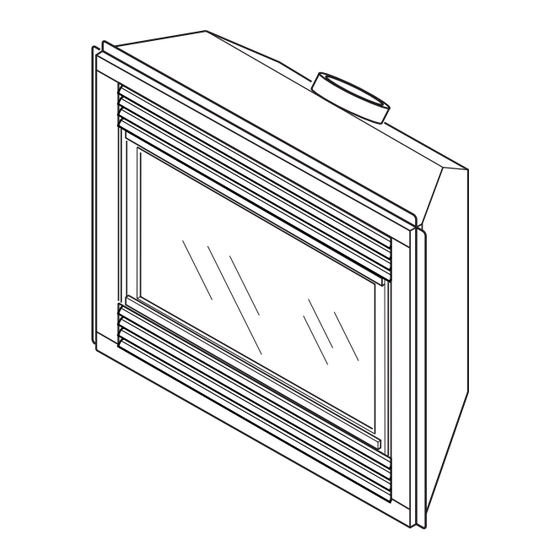
SAFETy INFORMATION PRODUCT Continued IDENTIFICATION 3. You must keep control compartments, burn- Upper Louver Flue Collar ers and circulating air passages clean. More Panel frequent cleaning may be needed due to ex- cessive lint and dust from carpeting, bedding Nailing material, etc. Turn off the gas valve and pilot Flange light before cleaning fireplace. Glass Door 4. Have venting system inspected annually by Assembly a qualified service person. If needed, have venting system cleaned or repaired. 5. Do not use any solid fuels (wood, coal, paper, cardboard, etc.) in this fireplace. Use only the gas type indicated on fireplace nameplate. -
Page 4: Pre-Installation Preparation
LOCATION AND SPACE termination cap. REqUIREMENTS • Do not locate termination cap where excessive Determine the safest and most efficient location snow or ice build up may occur. Be sure to for your FMI PRODUCTS, LLC direct-vent clear vent termination area after snow falls to fireplace. Make sure that rafters and wall studs prevent accidental blockage of venting system. are not in the way of the venting system. Choose When using snow blowers, do not direct snow a location where the heat output is not affected towards vent termination area. - Page 5 PRE-INSTALLATION PREPARATION 15" " " Continued " NOTICE: This fireplace is in- tended for use as supplemental heat. Use this fireplace along with " 41" your primary heating system. Do Nailing " Nailing Tabs not install this fireplace as your Tabs "...
-
Page 6: Location Of Termination Cap
LOCATION OF TERMINATION CAP Fixed Openable Fixed Closed Closed Openable TERMINATION CAP GAS METER RESTRICTED AREA AIR SUPPLY INLET (TERMINATION PROHIBITED) A = clearance above grade, veranda, porch, deck, or I = clearance to service regulator vent outlet [*72" (182.9 cm) balcony [*12"... -
Page 7: Venting Installation Instructions
These models are tested and approved for use with FMI PRODUCTS, LLC (direct-vent) pipe NOTICE: Failure to follow these in- components and terminations. structions will void the warranty. The venting system must terminate on the outside of... - Page 8 5. Carefully determine the location where the vent VENTINg INSTALLATION pipe assembly will penetrate the outside wall. INSTRUCTIONS The center of the hole should line up with the Continued center-line of the horizontal vent pipe. Mark the wall for a 11 " x 11 " square hole. Cut and INSTALLATION PLANNING frame the square hole in the exterior wall where There are two basic types of direct-vent in- the vent will be terminated. If the wall being stallation: penetrated is constructed of noncombustible • Horizontal Termination material, such as masonry block or concrete, • Vertical Termination " hole with zero clearance is acceptable (see Figure 9). horizontal Termination Installation IMPORTANT: Horizontal square terminations Female require only inner portion of wall firestop. Hori-...
- Page 9 VENTINg INSTALLATION INSTRUCTIONS Continued Vent Cap WARNING: Do not recess vent termination into any wall. This will cause a fire hazard. Position the Noncombustible Exterior Wall: horizontal vent cap in the center of the 8 " round hole and attach to the exterior wall with four wood screws provided. Before attaching the vent cap to exterior wall, run a bead of Wood Screw non-hardening mastic (pliable sealant) around Figure 10 - Installing Horizontal Vent Cap the outside edges to make a seal between it and...
- Page 10 VENTINg INSTALLATION GROUND FLOOR INSTALLATION Recommended Applications: INSTRUCTIONS • Installation using cabinet surrounds Continued • Through the wall using round or square termina- tion (up to 12" Adjustable pipe) Minimum Pipe Siding Standoff Overlap 1 " • NOT FOR CORNER INSTALLATION Direct-Vent Adjustable Pipe Horizontal Screws Pipe 12" Max. 45° Elbow High Wind Square Wall Termination Firestop Wall Firestop Maintain 1"...
- Page 11 VENTINg INSTALLATION INSTRUCTIONS Continued CORNER INSTALLATION Not to Exceed Recommended Applications: (H) Limits Square • Corner ground floor installation Termination 90° Elbow • Ground floor installation where pipe vents horizon- tally through wall (over 12" horizontal pipe) • Basement installation where one foot clearance from ground to termination is possible Wall 90° Elbow 12" Min. Not to Exceed (H) Limits Firestop Square As Required Termination for (V), See Chart for 45°...
- Page 12 VENTINg INSTALLATION INSTRUCTIONS Continued hORIZONTAL SYSTEM INSTALLATION USING TWO 90° ELBOWS The following configurations show the minimum vertical rise requirements for a horizontal system using two 90° elbows. 45° Elbow Venting with Two 90° Elbows horizontal (h Vertical (V) horizontal (h horizontal (h 5' min. 2' max. 6' max. 6' min. 4' max. 12' max. 7' min.
-
Page 13: Flat Ceiling Installation
VENTINg INSTALLATION Flat Ceiling Installation 1. Cut a 11 " square hole in the ceiling using INSTRUCTIONS the locating hole as a center point. The open- Continued ing should be framed to 11 " x 11 " (29.21 cm x 29.21 cm) inside dimensions, as shown INSTALLATION FOR VERTICAL in Figure 9 on page 8 using framing lumber TERMINATION the same size as the ceiling joists. If the area Note: Vertical restrictor must be installed in all above the ceiling is an insulated ceiling or an vertical installations. attic space, nail firestop from the top side. This 1. Determine the route your vertical venting prevents loose insulation from falling into the will take. If ceiling joists, roof rafters or other required clearance space. If the area above the framing will obstruct the venting system, ceiling is a living space, install firestop below consider an offset (see Figure 19) to avoid cut- the framed hole. The firestop should be installed... - Page 14 VENTINg INSTALLATION Vertical Termination Configurations Figures 21 through 24 show four different con- INSTRUCTIONS figurations for vertical termination. Continued Venting with Two 90° Elbows 5. Place the flashing over the pipe section(s) horizontal (h extending through the roof. Secure the base of Vertical (V) horizontal (h the flashing to the roof and framing with roof- 5' min. 2' max. ing nails. Be sure roofing material overlaps the 6' min.
- Page 15 VENTINg INSTALLATION INSTRUCTIONS Continued Vertical Venting V = 40' max. Note: Install restrictor into Note: Install inner collar of restrictor into fireplace as inner collar of shown. fireplace as shown. 45° Elbow 45° Elbow Venting with Two 90° Elbows Figure 24 - Vertical Venting Vertical (V horizontal (h) Configuration With No Horizontal Run...
-
Page 16: Replacement Parts
Termination Kit, Galvanized PARTS LIST FOR VENTING KITS HTS-58 Horizontal Square Termination, AND COMPONENTS Galvanized HTKS-58 Horizontal Square Termination Kit FMI PRODUCTS, LLC (5"/8") Pipe & Vent (Includes: Square Termination, Kits Wall Firestop, 45° Elbow) Number Description VT-58 Vertical Round Termination, P58-6 6"... -
Page 17: Technical Service
REPLACEMENT PARTS FACE/LOUVER PANEL KIT (Not Shown) Continued FPD36 - Filigree, Black PARTS NOT UNDER WARRANTY FPD36B - Filigree, Brushed Brass Contact authorized retailers of this product. If they FPD36P - Filigree, Platinum can not supply original replacement part(s), call FMI PRODUCTS, LLC at 1-866-328-4537 for RLD42 - Rolled Louver, Black referral information. FPD42 - Filigree, Black When calling, have ready FPD42B - Filigree, Brushed Brass • model number of your fireplace FPD42P - Filigree, Platinum • the replacement part number LOUVER TRIM KIT (Rolled Louvers Only) (Not Shown) -
Page 18: Illustrated Parts Breakdown And Parts List
ILLUSTRATED PARTS BREAkDOWN MODELS (V)DVC36(B)(h) AND (V)DVC42(B)(h) www.fmiproducts.com 118197-01D... -
Page 19: Parts List
PARTS LIST MODELS (V)DVC36(B)(h) AND (V)DVC42(B)(h) This list contains replaceable parts used in your fireplace. When ordering parts, follow the instructions listed under Replacement Parts on page 16 of this manual. (V)DVC36(B)(h) (V)DVC42(B)(h) DESCRIPTION qTY. Firebox Assembly Face Weldment 108010-01 108328-01 Door Assembly — 108328-02 Door Assembly (V Models Only) 108011-01 108331-01 Top Louver Assembly 108011-02 108331-02 Bottom Louver Assembly Fireplace Top Fireplace Top Insulation Fireplace Surround 109082-01... - Page 20 THIS WARRANTy Model (located on product or identification tag) _____________________________ Serial No. (located on product or identification tag) __________________________ Date Purchased __________________________ Keep receipt for warranty verification. FMI PRODUCTS, LLC LIMITED WARRANTIES New Products Standard Warranty: FMI PRODUCTS, LLC warrants this new product and any parts thereof to be free from defects in material and workmanship for a period of two (2) years from the date of first purchase from an authorized dealer provided the product has been installed, maintained and operated in accordance with FMI PRODUCTS, LLC’s warnings and instructions. For products purchased for commercial, industrial or rental usage, this warranty is limited to 90 days from the date of first purchase.
Need help?
Do you have a question about the DVC36B and is the answer not in the manual?
Questions and answers