
Related Manuals for NI 9269


Summary of Contents for NI 9269
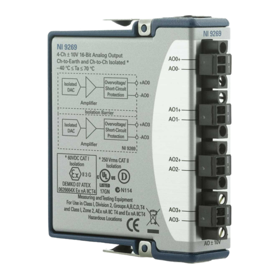
- Page 1 OPERATING INSTRUCTIONS AND SPECIFICATIONS NI 9269 4-Channel, ±10 V, 16-Bit, Simultaneous, Channel- to-Channel Isolated Analog Voltage Output Module Français Deutsch ni.com/manuals...
- Page 2 This document describes how to use the National Instruments 9269 and includes specifications and terminal assignments for the NI 9269. Visit and enter to determine ni.com/info rdsoftwareversion which software you need for the modules you are using. For information about installing, configuring, and programming the system, refer to the system documentation.
-
Page 3: Safety Guidelines For Hazardous Voltages
Safety Guidelines Operate the NI 9269 only as described in these operating instructions. This icon denotes that the component may be Hot Surface hot. Touching this component may result in bodily injury. Safety Guidelines for Hazardous Voltages If hazardous voltages are connected to the module, take the following precautions. - Page 4 LIVE (>42.4 V /60 VDC), you must ensure that devices and circuits connected to the module are properly insulated from human contact. You must use the NI 9971 connector backshell kit to ensure that the terminals are not accessible. Figure 1 shows the NI 9971 connector backshell.
-
Page 5: Safety Guidelines For Hazardous Locations
Safety Guidelines for Hazardous Locations The NI 9269 is suitable for use in Class I, Division 2, Groups A, B, C, D, T4 hazardous locations; Class I, Zone 2, AEx nA IIC T4, and Ex nA IIC T4 hazardous locations; and nonhazardous locations only. - Page 6 II 3G and is suitable for use in Zone 2 hazardous locations, in ambient temperatures of –40 °C ≤ Ta ≤ 70 °C. If you are using the NI 9269 in Gas Group IIC hazardous locations, you must use the device in an NI chassis that has been evaluated as Ex nC IIC T4, EEx nC IIC T4, Ex nA IIC T4, or Ex nL IIC T4 equipment.
- Page 7 Power supply and module cables must be separated on opposite sides of the enclosure and must enter and exit through opposing enclosure walls. © National Instruments Corp. NI 9269 Operating Instructions and Specifications...
-
Page 8: Connecting The Ni 9269
Connecting the NI 9269 The NI 9269 has four 2-terminal detachable screw-terminal connectors that provide connections for 4 analog output channels. AO0+ AO0– AO1+ AO1– AO2+ AO2– AO3+ AO3– Figure 2. NI 9269 Terminal Assignments NI 9269 Operating Instructions and Specifications... - Page 9 You can connect a load to each channel of the NI 9269. Connect the positive lead of the load to the AO+ terminal. Connect the ground of the load to the corresponding AO– terminal. Refer to Figure 3 for an illustration of how to connect a load to the NI 9269.
- Page 10 Isolated Short-Circuit Protection AO – NI 9269 Figure 4. Output Circuitry for One Channel of the NI 9269 When the module powers on, the channels output the startup voltage. Refer to the Specifications section for more information about startup voltage. Refer to the software help for information about configuring startup output states in software.
-
Page 11: Wiring For High-Vibration Applications
If an application is subject to high vibration, National Instruments recommends that you either use ferrules to terminate wires to the detachable screw-terminal connector or use the NI 9971 backshell kit to protect the connections. Refer to Figure 5 for an illustration of using ferrules. -
Page 12: Increasing Output Voltage Range
Increasing Output Voltage Range Each channel of the NI 9269 has a nominal output voltage range of ±10 V and can drive up to ±10 mA of current. The total output current of all channels is limited to ±20 mA. For example, if the output current of AO0 is ±10 mA, the output current of... - Page 13 Cascading more than four output channels of multiple NI 9269 modules violates the electrical safety and overvoltage protection ratings. Because the NI 9269 outputs can source and sink current, it is not possible to increase the current drive by connecting output channels in parallel.
-
Page 14: Sleep Mode
In sleep mode, the system consumes minimal power and may dissipate less heat than it does in normal mode. Refer to the Specifications section for more information about power consumption and thermal dissipation. NI 9269 Operating Instructions and Specifications ni.com... -
Page 15: Specifications
When the output stage powers on, a glitch occurs for 5 μs peaking at –900 mV. When the module powers down, a glitch occurs for 20 μs peaking at –600 mV. © National Instruments Corp. NI 9269 Operating Instructions and Specifications... - Page 16 Current drive ........±20 mA all channels max; ±10 mA per channel typ Output impedance......100 mΩ Refer to the Increasing Output Voltage Range section for the cascaded nominal output voltage range and current drive. NI 9269 Operating Instructions and Specifications ni.com...
- Page 17 Uncalibrated, typ (25 °C, ±5 °C) 0.14% 0.05% Range equals 10.47 V Stability Gain drift ........14 ppm/°C Offset drift ........80 μV/°C Protection Overvoltage ........ ±30 V Short-circuit........ Indefinitely © National Instruments Corp. NI 9269 Operating Instructions and Specifications...
- Page 18 Channel-to-channel ....100 dB Common-mode voltage ....120 dB Settling time 100 pF load, to 1 LSB Full-scale step ...... 20 μs 1 V step ........ 10 μs 0.1 V step ......10 μs NI 9269 Operating Instructions and Specifications ni.com...
-
Page 19: Power Requirements
Power consumption from chassis Active mode ....... 1 W max Sleep mode ......... 120 μW max Thermal dissipation (at 70 °C) Active mode ....... 1.4 W max Sleep mode ......... 77 mW max © National Instruments Corp. NI 9269 Operating Instructions and Specifications... -
Page 20: Physical Characteristics
Torque for screw terminals ....0.5 to 0.6 N · m (4.4 to 5.3 lb · in.) Ferrules ..........0.25 mm to 0.5 mm Weight..........147 g (5.2 oz) NI 9269 Operating Instructions and Specifications ni.com... - Page 21 Measurement Category II Withstand........2,300 V , verified by a 5 s dielectric withstand test Division 2/Zone 2 hazardous locations applications (Channel-to-channel and channel-to-earth ground) ....60 VDC, Measurement Category I © National Instruments Corp. NI 9269 Operating Instructions and Specifications...
- Page 22 115 V for U.S. or 230 V for Europe. Do not connect to signals or use for Caution measurements within Measurement Categories III or IV. NI 9269 Operating Instructions and Specifications ni.com...
- Page 23 • IEC 61010-1, EN 61010-1 • UL 61010-1, CSA 61010-1 For UL and other safety certifications, refer to the Note product label or the Online Product Certification section. © National Instruments Corp. NI 9269 Operating Instructions and Specifications...
-
Page 24: Electromagnetic Compatibility
ICES-001: Class A emissions For the standards applied to assess the EMC of this Note product, refer to the Online Product Certification section. For EMC compliance, operate this device with Note shielded cables. NI 9269 Operating Instructions and Specifications ni.com... -
Page 25: Online Product Certification
To obtain product certifications and the DoC for this product, visit ni.com/ , search by module number or product line, and certification click the appropriate link in the Certification column. © National Instruments Corp. NI 9269 Operating Instructions and Specifications... -
Page 26: Shock And Vibration
Shock and Vibration To meet these specifications, you must panel mount the system and either affix ferrules to the ends of the terminal wires or use the NI 9971 backshell kit to protect the connections. Operating vibration Random (IEC 60068-2-64)..5 g , 10 to 500 Hz Sinusoidal (IEC 60068-2-6) .. -
Page 27: Environmental Management
NI recognizes that eliminating certain hazardous substances from our products is beneficial to the environment and to NI customers. For additional environmental information, refer to the NI and the Environment Web page at . This page ni.com/environment... - Page 28 (For information ni.com/environment/rohs_china about China RoHS compliance, go to ni.com/ environment/rohs_china Calibration You can obtain the calibration certificate and information about calibration services for the NI 9269 at ni.com/calibration Calibration interval ......1 year NI 9269 Operating Instructions and Specifications ni.com...
-
Page 29: Where To Go For Support
Finland 358 (0) 9 725 72511, France 01 57 66 24 24, Germany 49 89 7413130, India 91 80 41190000, Israel 972 3 6393737, Italy 39 02 41309277, Japan 0120-527196, © National Instruments Corp. NI 9269 Operating Instructions and Specifications... - Page 30 South Africa 27 0 11 805 8197, Spain 34 91 640 0085, Sweden 46 (0) 8 587 895 00, Switzerland 41 56 2005151, Taiwan 886 02 2377 2222, Thailand 662 278 6777, Turkey 90 212 279 3031, United Kingdom 44 (0) 1635 523545 NI 9269 Operating Instructions and Specifications ni.com...
- Page 31 National Instruments, NI, ni.com, and LabVIEW are trademarks of National Instruments Corporation. Refer to the Terms of Use section on ni.com/legal for more information about National Instruments trademarks. Other product and company names mentioned herein are trademarks or trade names of their respective companies.
Need help?
Do you have a question about the 9269 and is the answer not in the manual?
Questions and answers