Advertisement
Quick Links
Advertisement

Subscribe to Our Youtube Channel
Related Manuals for Primo International EZ Base

Summary of Contents for Primo International EZ Base
- Page 1 EZ Base Assembly Instructions...
- Page 2 We at Primo International would like to thank you for your purchase. Now that your new product has been delivered to you, let us help you through its assembly so you can enjoy it fully. STEP 1 Open the packaging at the end where the handle is and identify the location of the upholstered frames inside the packaging.
- Page 3 STEP 2 Open the packaging after making sure the upholstered frames inside the box are on the opposite side to avoid damaging the material. STEP 3 Remove all pieces from the packaging and make sure there is nothing left inside the carton before disposing of it. Please pay attention to any small hardware that could have come loose.
- Page 4 STEP 4 Remove the components from the protective material and place them on a clean, flat and levelled surface, this is important. The box should contain the following pieces: 2x Side frames (A) 2x End frames (B) 1x Center rail (C) 10x Slats (D) 1x Cover (E) 1x Hardware (F) pack STEP 5 Identify the content of the Hardware pack (F): 4x Legs (H) 4x Corner brackets (I) 1x Support leg (J) 2x Headboard bracket (K) 2x Center rail Bracket (L)
-
Page 5: Important Note
26x Bolts (M) 26x Washers (N) 4x Carriage bolts (O) 4x Flat washers (P) 4x Nuts (Q) 4x Wood screws (R) 1x Spanner (S) 1x Allen key (T) IMPORTANT NOTE Do not use a power tool to assemble this product as it could damage the thread of the hardware and affect the solidity/durability of the product. - Page 6 STEP 6 Now that you have identified all components, we can start the assembly process but first, pay close attention to the following detail: IMPORTANT NOTE The corner brackets are fitted with round holes and rounded rectangle holes. The round holes must be used to attach the bracket to the Side Frames (A) and the rounded rectangle holes used to attach the bracket to the End frames (B) Round hole Rounded rectangle hole...
- Page 7 STEP 7 Use the bolt (M) and washer (N) to attach the 2 center rail bracket (L) to the end frames (B). The bracket must be installed upward as illustrated below. Adjust the brackets to be straight and level against the top of the frame and tighten using the Allen key (T) ...
- Page 8 STEP 8 Attach the 4 corner brackets (I) to the 2 end frames (B) with the bolts (M) and washers (N) using the rounded rectangle holes. Do not fully tighten the bolts at this stage, leave them loose. Rounded rectangle hole The bottom of the corner bracket is fitted with a plate where the legs will attach on. Insure to position the bracket so the plate is at the same level to the bottom of the frame.
- Page 9 STEP 9 Attach the side frame (A) to the end frame (B) using bolts (M) and washers (N) Leave the bolt loose, do not tighten at this stage of the assembly...
- Page 10 STEP 10 Complete attaching all frames but leave all bolts loose STEP 11 Adjust each corner so the end on the side frame (A) correctly lines up with end of end frame (B) then thighten the bolts.
- Page 11 STEP 12 Put the frame on its side and attach the legs (H) to the corner brackets base Once all 4 legs have been attached, please re‐check that all bolts are evenly tighten. ...
- Page 12 STEP 13 Take the center rail (C) and the support leg (J). Locate the attachment screws on the center rail Attach the support leg (J) to the center rail (C) using the bolts (M) and washers (N). VERY IMPORTANT, the bolts must be attached from the opposite side of where the attachment nut is flush against the rail. This is the wrong side. Correct side to attach the support leg...
- Page 13 STEP 14 Once the support leg is attached to the center rail, place the center rail in the center rail brackets.
- Page 14 STEP 15 2 of the wooden slats (D) are fitted with holes which will be used to attach them to the side frames. Those 2 slats are to be placed in the center of the base as illustrated below. ...
- Page 15 Use a Phillips (star head) screw driver to attach the 2 middle slats to the side frames using the wood screws (R) Your new platform base can now be covered.
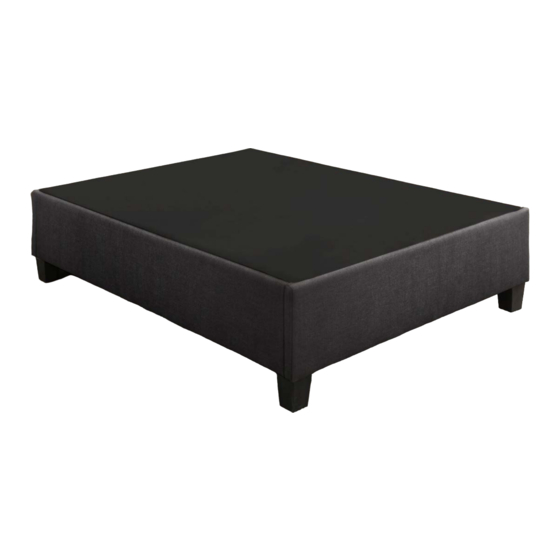
- Page 16 LAST STEP Use the cover (E) to recover the frame and voila, your new platform base is ready for use.
- Page 17 OPTIONAL STEPS FOR HEADBOARD Should you decide to use your new platform base with a headboard, the required hardware is already provided with the pack you received. STEP: Take the headboard bracket (K) provided with the hardware pack of your base and identify which holes on the bracket corresponds to the attachment holes on your headboard. STEP: Once you have identified the matching holes, put 1 carriage bolt (O) in each matching hole (In the illustration below, the washer (P) and nut (N) are used to keep the carriage bolts in place only)
- Page 18 STEP: Attach the headboard bracket (K) to the end frame (B) that is already fitted with pre‐drilled holes using the bolts (M) and washers (N). Adjust the height of the braket by sliding it up or down. Once at the desired height, make sure the bracket is straight and tighten the bolts.
- Page 19 STEP: You can slide the carriage bolts side‐to‐side to fit into the head‐ board attachment holes after removing the nut and washer. Once the headboard (not Illustrated) is in place, use the spanner (S) to tighten it to the headboard brackets using the Washers (P) and nuts (Q).
Need help?
Do you have a question about the EZ Base and is the answer not in the manual?
Questions and answers