Table of Contents
Advertisement
Quick Links
Download this manual
See also:
User Manual
Advertisement
Table of Contents

Related Manuals for Sony SDX-500 Series


Summary of Contents for Sony SDX-500 Series
-
Page 1: Installation Manual
Installation Manual SDX-500 Series Ver.2.0 AIT Drive Sony Corporation... -
Page 2: Table Of Contents
Location of 3 LEDs ....................9 LED Indication for Drive Status ................ 10 Drive Operation ..................11, 12, 13 Interface Implementation ................... 14 Supported SCSI Messages ................... 14 Supported SCSI Commands ................14 Specification ......................15 Product Specifications ................... 15, 16 Sony Contacts ....................... 17... - Page 3 Intelligent tape (AIT) technology. The SDX-500 series drive achieves high data reliability through Read-After-Write, an additional level of Error Correction Code, and other features. The Sony SDX-500 series drive stores data on tape using a standard format called AIT (Advanced Intelligent Tape) and ALDC formats.
-
Page 4: Table Of Contents
Introduction Product Features SDX-500 series Data Capacity 50 G Byte capacity (with AIT-2 230m tape) (approximately 100 G Byte to 150 G Byte with Data Compression ) Transfer Rate 6 M Byte/sec (with AIT-2 format) (sustained) (approximately 12 M Byte/sec to 18 M Byte/sec with Data Compression) Data compression function is available with SDX-500C and 510C. -
Page 5: Precautions
Precautions Installation Avoid placing the drive in a location subject to: - high humidity - high temperature - mechanical shock and vibration - direct sunlight Operation • Do not move the drive while it is operating. It may cause malfunction. •... -
Page 6: Installation
Installation SCSI Connection/Setting the SCSI ID SCSI ID SCSI ID SCSI 68pin Connector Jumpers Power Connector GND GND 12 V Parity Disable Enable Note : = CLOSED/Jumper OPEN/Jumper not installed Don’t care Parity Disable Jumper Parity check function can be disabled by Jumper. Parity check is disabled while left end jumper is installed. -
Page 7: Option Switches (Dip Switch)
Option Switches ( DIP Switch ) DIP Switch DIP Switch Positions Reserved (OFF) Reserved (OFF) Reserved (OFF) Reserved (OFF) Terminator Power (ON) Reserved (OFF) DC Control (1) (ON) DC Control (2) (OFF) Data Compression Control DIP switch Data compression can be selected by DIP switches. Data compression is enabled while position 7 [DC Control (1)] is ON. -
Page 8: Mounting Holes
Mounting Holes for 3.5" Standard Height (SDX-500C) 4.7±0.5 mm (0.185 In) 92.71mm (3.65 In) 8 mm (0.315 In) 3-M3 (depth 2.5mm) (depth 0.10 In) 6-M3 (depth 2.5mm) (depth 0.10 In) 5±0.3 mm 94±0.3 mm (0.20 In) (3.70 In) 41.2±0.5 mm 101.6±0.5 mm (1.62 In) (4.00 In) - Page 9 Mounting Holes for 3.5" Standard Height (SDX-510C) 4.7±0.5 mm (0.185 In) 92.71mm (3.65 In) 8 mm (0.315 In) 3-M3 (depth 2.5mm) (depth 0.10 In) 6-M3 (depth 2.5mm) (depth 0.10 In) 5±0.3 mm (0.20 In) 94±0.3 mm (3.70 In) 41.2±0.5 mm (1.62 In) 101.6±0.5 mm (4.00 In)
-
Page 10: Orientation
Orientation 10° 10° 10° 10° 10° 10° 10° 10°... -
Page 11: Operation
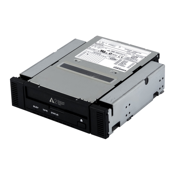
Operation Location of 3 LEDs There are three LED indications (BUSY,TAPE and STATUS ) and an EJECT button on the front panel of the unit. Front Panel (for 3.5" Standard Height) Advanced Intelligent Tape BUSY TAPE STATUS... -
Page 12: Led Indication For Drive Status
LED Indication for Drive Status The LED indicators are defined as follows STATE BUSY TAPE STATUS Activity Cartridge Other None None None SCSI None None Drive Loading/Unloading None Drive Loading/Unloading Write Protected None Loaded Cleaning Tape at EOM None Loaded None SCSI Loaded... -
Page 13: Drive Operation
Using a Cleaning Cassette In case of SDX-500 series, a cleaning function is built in the drive and hence, a periodic cleaning using cleaning cassette such as other format requires is not necessary. However, when the drive does not recover at the worst case, cleaning cassette is... -
Page 14: Emergency Tape Removal Procedure
6. After the tape slack has been removed, turn the screw located on the right side of the drive clockwise by a precision screwdriver until the tape cartridge is lifted out of the drive mechanism and is ejected. 7. Return the drive to Sony for repair. 3. Cassette Compartment Motor 2. Reel Motor... - Page 15 tape guide surface tape guide surface detail A Cartridge Photo-1: The Initial Position of the Threading Mechanism Caution: Stop rotating the motor shaft immediately, when the guide B (see detail A of Photo-1) gets to the area below the line C-C (This line is defined by 2 circular tape guide surfaces of the cartridge).
-
Page 16: Interface Implementation
Interface Implementation Supported SCSI Messages Abort Message Parity Error Bus Device Reset Message Reject Command Complete No Operation Disconnect Restore Pointers Extended Message Save Data Pointer - Synchronous Data Transfer Request - Wide Data Transfer Request Identify ( w/&w/o Disconnect ) Ignore Wide Residue Supported SCSI Commands Erase... -
Page 17: Specification
Specification Product Specifications Dimensions Acoustic Noise (A) curve weight SDX-500C Streaming Write/Read 35 db (A) SDX-510C Height 41.2 mm (1.62 in) Insert/Eject 41.2 mm (1.62 in) 60 db (A) Width 101.6 mm (4.0 in ) 101.6 mm (4.0 in ) Note: The sound-meter on (A) scale is located 1 m Depth 155.0 mm ( 6.1 in ) in front of the center of the drive front panel. -
Page 18: Power Requirements
Power Requirements Current Model Voltage Max Ripple Typical Maximum 5V +/– 5% 100 mVp-p 1.5 A 2.5 A SDX-500C 12 V +/– 10% 150 mVp-p 0.4 A 1.2 A 5V +/– 5% 100 mVp-p 1.6 A 2.5 A SDX-510C 12 V +/– 10% 150 mVp-p 0.4 A 1.2 A... -
Page 19: Sony Contacts
Gotenyama Hills, 4-7-35, Kitashinagawa, Shinagawa-Ku, Tokyo, 140-0001 Japan TEL: 81- (0) 3-5448-2289 FAX: 81- (0) 3-5448-7902 Sony of Canada Ltd., Computer and Personal Information Division 405 Gordon Baker Road, Willowdale, Ontario, Canada M2H 2S6 S TEL: (416) 718-5050 or (1) 800-961-7669... - Page 20 The information contained in this document is subject to change without notice. SONY MAKES NO WARRANTY OF ANY KIND WITH REGARD TO THIS DOCUMENT. Sony shall not be liable for error contained herein, indirect, special, incidental or consequential damages in connection with the furnishing, performance or use of this document.
Need help?
Do you have a question about the SDX-500 Series and is the answer not in the manual?
Questions and answers