Advertisement
Service Manual
Specification
Detail
Power Source
Cooking
Power
consumption
Warming
Cooking capacity
Center thermostat
working temperature
Keep warm temperature
Thermal fuse specification
Dimension (mm)
Width x Depth x Height
Weight
Power Cord (approx.)
Accessories
Specification subject to change without notice.
Model
SR-G06G
300W
-
0.18 ~ 0.6 L
254 x 201 x 209
1.5 kg
Rice Scoop
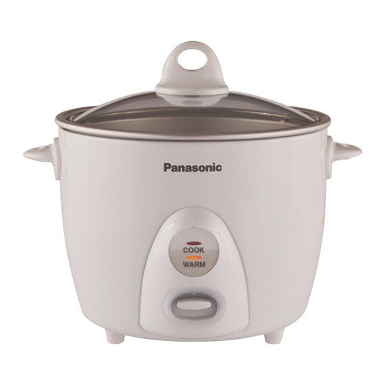
Automatic Rice Cooker
SR-G06G/G10SG/G18SG
SR-G10SG
1 Phase AC 120V 60 Hz
43.7W
0.18 ~ 1.0 L
134 °C ± 6 °C
More than or equal to 80 °C (After 1 Hr. keep warm)
110 °C 250V 10A
282 x 229 x 238
© 2007 Panasonic Home Appliance (Thailand) Co.,Ltd
All rights reserved. Unauthorized copying and distrbution
is a violation of law.
Order No. PHAT070801S3
(Hong Kong)
450W
2.1 kg
1.0 m
Measuring Cup, Steaming Basket
SR-G18SG
650W
45W
0.54 ~ 1.8 L
325 x 283 x 255
2.7 kg
Advertisement
Table of Contents
Troubleshooting

Related Manuals for Panasonic SR-G06G


Summary of Contents for Panasonic SR-G06G
- Page 1 2.1 kg 2.7 kg Power Cord (approx.) 1.0 m Accessories Rice Scoop Measuring Cup, Steaming Basket Specification subject to change without notice. © 2007 Panasonic Home Appliance (Thailand) Co.,Ltd All rights reserved. Unauthorized copying and distrbution is a violation of law.
-
Page 2: Table Of Contents
SR-G06G/SR-G10SG/SR-G18SG CONTENTS Page 1. SCHEMATIC DIAGRAM & WIRING DIAGRAM ................3-4 2. FUNCTION OF CENTER THERMOSTAT AND THERMAL FUSE ..........5-6 3. TROUBLE SHOOTING GUIDE .....................7-8 4. TEST PROCEDURE ........................9-10 5. EXPLODED VIEW .......................... 11 6. REPLACEMENT OF PARTS LIST & PACKING LIST ..............12-14 WARNING This service information is designed for experienced repair technicians only and is not designed for use by the general public. -
Page 3: Schematic Diagram & Wiring Diagram
SR-G06G/SR-G10SG/SR-G18SG 1. SCHEMATIC DIAGRAM & WIRING DIAGRAM SCHEMATIC DIAGRAM (SR-G06G) LAMP BORD COOKING NEON LAMP KEEP WARM NEON LAMP T. F. LAMP RESIST. LAMP RESIST. BLUE WHITE YELLOW CAST HEATER MICA HEATER ASS’Y GREEN INPUT SWITCH WIRING DIAGRAM (SR-G06G) Red tube (N) -
Page 4: Schematic Diagram & Wiring Diagram
SR-G06G/SR-G10SG/SR-G18SG 1. SCHEMATIC DIAGRAM & WIRING DIAGRAM SCHEMATIC DIAGRAM (SR-G10SG/SR-G18SG) LAMP BORD SWITCH COOKING NEON LAMP T. F. LAMP RESIST. BLUE YELLOW GREEN INPUT CAST HEATER WIRING DIAGRAM (SR-G10SG/SR-G18SG) Red tube (N) Insulation Color : Blue In case of wire broken, make sure that... -
Page 5: Function Of Center Thermostat And Thermalfuse
SR-G06G/SR-G10SG/SR-G18SG 2. FUNCTION OF CENTER THERMOSTAT AND THERMALFUSE A. Center Thermostat The center thermostat senses when the bottom of the rice cooker pan reach 134°C ± 6°C. And it’s action turns off the cooking cycle, and starts the warming cycle. - Page 6 SR-G06G/SR-G10SG/SR-G18SG 2. FUNCTION OF CENTER THERMOSTAT AND THERMALFUSE C. Thermal Fuse The thermal fuse is used to open the circuit to the cooking heater when the temperature has gone unusually high. This happens in cases such as incomplete contact between the heater and pan or if the switch buttons is forced to stay on keeping the heater energized abnormally.
-
Page 7: Troubleshooting Guide
SR-G06G/SR-G10SG/SR-G18SG 3. TROUBLESHOOTING GUIDE When receiving the cooker to be repaired, be sure to always take charge of not only the cooker body but also the pan and the lid, and ask for details as to the symptom of the trouble. -
Page 8: Trouble Shooting Guide
SR-G06G/SR-G10SG/SR-G18SG 3. TROUBLESHOOTING GUIDE Symptom Diagnosis Remedy ● Earlier Switching-off ● Poor cooking finish Poor contact between pan and sheathed ● Replace pan or sheathed heater? (Check with bubbling test) heater. Too hard Too soft Half-boiled Center thermostat defective? ● Replace Center thermostat. -
Page 9: Test Procedure
SR-G06G/SR-G10SG/SR-G18SG 4. TESTING PROCEDURE 1. Bubbling test Input the pan in the main body, and lightly rotate the pan clockwise and counter clockwise to set the pan on the heating plate properly. 1. Fill water until the center area of the pan bottom is dipped, and close the lid. Then turn on the boiling switch. - Page 10 SR-G06G/SR-G10SG/SR-G18SG 4. TESTING PROCEDURE 3. Boiling control lever adjustment Such a mechanical operation as center thermostat goes up and down is used to turn on and off the micro-switch. Check and adjust this relationship as shown below. When the boiling switch is turned on.
-
Page 11: Exploded View
SR-G06G/SR-G10SG/SR-G18SG 5. EXPLODED VIEW... -
Page 12: Replacement Of Parts List & Packing List
SR-G06G/SR-G10SG/SR-G18SG 6. REPLACEMENT OF PARTS LIST & PACKING LIST PARTS LIST Part Name Part Number SR-G06G SR-G10SG SR-G18SG Remark AQB01T280-WU GLASS LID ASS’Y White AQB01T280-EG GLASS LID ASS’Y Silver AQB01T279-WU GLASS LID ASS’Y White AQB01T279-EG GLASS LID ASS’Y Silver AQB01T278-WU GLASS LID ASS’Y... -
Page 13: Replacement Of Parts List & Packing List
SR-G06G/SR-G10SG/SR-G18SG 6. REPLACEMENT OF PARTS LIST & PACKING LIST PARTS LIST Part Name Part Number SR-G06G SR-G10SG SR-G18SG Remark AQN65T270 WIRING TIED AQL65T270 WIRING TIED AQN20T272-WT DECORATIVE PANEL White AQN20T272-UH DECORATIVE PANEL Silver AQN20T270-WT DECORATIVE PANEL White AQN20T270-UH DECORATIVE PANEL... - Page 14 SR-G06G/SR-G10SG/SR-G18SG 6. REPLACEMENT OF PARTS LIST & PACKING LIST LIST OF SCREW Part Name Part Number SR-G06G SR-G10SG SR-G18SG Remark QB06T270 ALUMINIUM SCREW XYN4+C10FNS SEMS SCREW XTN4+10BFJ TAPPING SCREW XTN4+8BFJ TAPPING SCREW XTN4+6FFJ TAPPING SCREW XTN4+14BFJ TAPPING SCREW XYN4+C7FNS TAPPING SCREW...
Need help?
Do you have a question about the SR-G06G and is the answer not in the manual?
Questions and answers