
Summary of Contents for Inficom SQM-160
- Page 1 Cover Page SQM-160 ™ Multi-Film Rate/Thickness Monitor PN 074-511-P1E...
- Page 3 Title Page SQM-160 ™ Multi-Film Rate/Thickness Monitor PN 074-511-P1E ® www.inficon.com re achus@inficon.com ©2015 INFICON...
- Page 4 The trademarks of the products mentioned in this manual are held by the companies that produce them. INFICON® is a trademark of INFICON Inc. SQM-160™ and INFICON® are trademarks of INFICON GmbH. Visual Basic®, Windows®, and Excel® are registered trademarks of Microsoft Corporation.
- Page 7 Warranty WARRANTY AND LIABILITY - LIMITATION: Seller warrants the products manufactured by it, or by an affiliated company and sold by it, and described on the reverse hereof, to be, for the period of warranty coverage specified below, free from defects of materials or workmanship under normal proper use and service. The period of warranty coverage is specified for the respective products in the respective Seller instruction manuals for those products but shall not be less than two (2) years from the date of shipment thereof by Seller.
-
Page 9: Table Of Contents
SQM-160 Configurations ........ - Page 10 SQM-160 Operating Manual 2.1.2 Ground Requirements ......... 2-2 2.1.3...
- Page 11 SQM-160 Comm Software ........
- Page 12 SQM-160 Operating Manual 5.3.3 Calculating the CRC......... . 5-11 Commands .
- Page 13 SQM-160 Operating Manual Chapter 8 Measurement and Theory Basics ............8-1 8.1.1...
- Page 14 SQM-160 Operating Manual This page is intentionally blank. TOC - 6...
-
Page 15: Introduction And Specifications
® software that allows instrument setup from a computer. The software can be used to set and store all parameters, operate SQM-160, and save process data in a .txt file that can be ® imported into Excel . Universal Serial Bus (USB) or Ethernet options add to the communications flexibility. -
Page 16: Related Manuals
SQM-160 Operating Manual 1.1.1 Related Manuals Quartz crystal sensors are covered in separate manuals. The following manuals are available on the Thin Film Instrument and Sensor Manuals CD (PN 074-5000-G1), part of the ship kit: PN 074-154 - UHV Bakeable Sensor ... -
Page 17: General Safety Information
SQM-160 Operating Manual 1.2.2 General Safety Information WARNING Do not open the SQM-160 case. Refer all maintenance to qualified personnel. There are no user-serviceable components within the SQM-160 case. Dangerous voltages may be present whenever the power cable or external input/relay connectors are present. -
Page 18: Earth Ground
Repair Service When experiencing a problem with SQM-160, please have the following information readily available: The Sales Order or Purchase Order number of the SQM-160 purchase The version of SQM-160 firmware The version of Windows operating system ... -
Page 19: Returning Sqm-160
SQM-160 Operating Manual 1.3.1 Returning SQM-160 Do not return any component of SQM-160 to INFICON before speaking with a Customer Support Representative and obtaining a Return Material Authorization (RMA) number. SQM-160 will not be serviced without an RMA number. Packages delivered to INFICON without an RMA number will be held until the customer is contacted. -
Page 20: Film Parameters
SQM-160 Operating Manual 1.4.2 Film Parameters Stored Films ....99 Density ..... . . 0.50 to 99.99 g/cm Tooling . -
Page 21: Digital I/O
SQM-160 Operating Manual 1.4.4 Digital I/O Digital Inputs....4 Functions ..... Open Shutter, Close Shutter, Zero Thickness, Zero Time Input Rating . -
Page 22: Unpacking And Inspection
1.6 Configurations and Accessories 1.6.1 SQM-160 Configurations SQM-160 ......SQM160-X-X-X Consult the figure below for possible configurations. -
Page 23: Accessories
15.2 cm (6 in.) to 78.1 cm (30.75 in.). 1.6.2.2 Rack Mounting Options Rack mount kits allow one or two SQM-160 instruments to be installed in a standard 48.3 cm (19 in.) rack. Full Rack Extender (one SQM-160) ..PN 782-900-008 Rack Adapter (two SQM-160s) . -
Page 24: Sensors
NOTE: X indicates user-selectable option (see www.inficon.com for Sensor Datasheets). NOTE: All shuttered sensors require a feedthrough with an air line and a solenoid valve (PN 750-420-G1). NOTE: Multi-crystal (rotary) sensor should not be used with SQM-160. 1 - 10... -
Page 25: Installation
Quartz crystals appropriate for the application CAUTION To maintain proper SQM-160 performance, use only the 15.2 cm (6 in.) BNC cable, included in the oscillator kit, to connect the oscillator to the crystal sensor. The in-vacuum cable (Front Load and Sputtering Sensors) or electrical conduit tube (Cool Drawer, ALD, and UHV Bakeable Sensors) should not exceed 78.1 cm... -
Page 26: Ground Requirements
(see Figure 2-1 for the recommended grounding method). The oscillator is grounded to SQM-160 and crystal sensor through the BNC cables. The crystal sensor is typically grounded to the wall of the vacuum system. If the sensor feedthrough is not properly grounded to earth through the vacuum system, connect a copper strap between the feedthrough and the common ground point on the vacuum system. -
Page 27: Establishing Earth Ground
NOTE: Do not use braided wire. Use a solid copper strap. 2.2 Rack Mounting Procedure SQM-160 is designed to mount in a standard 48.3 cm (19 in.) rack using optional rack mount kits or can be used on a benchtop. -
Page 28: Installation
SQM-160 Operating Manual 2.2.1.2 Installation Assemble the Extender Use the eight small flat-head screws to connect the two small black aluminum panels and two large black aluminum panels (see Figure 2-2). Figure 2-2 Assembly of extender Small flat head screws... - Page 29 SQM-160 Operating Manual Install Hex Shoulder Screws From inside the extender, thread two hex shoulder screws on one side, closest to the front of SQM-160. Continue to thread the screws until the threads are completely exposed (see Figure 2-3 Figure 2-4).
- Page 30 Align the extender with SQM-160 to fit the rack. The hex shoulder screws installed in step 2 need to align with the two large threaded holes in SQM-160. Tighten the hex shoulder screws to secure the extender to SQM-160 (see Figure 2-5).
- Page 31 Install the Rack Mount Ears Using the four large flat-head screws provided, install the rack mount ears onto the outer ends of the instrument assembly. Install one rack mount ear to SQM-160, and the other to the extender (see Figure 2-6 Figure 2-7).
-
Page 32: Rack Adapter
SQM-160 Operating Manual 2.2.2 Rack Adapter The optional Rack Adapter (PN 782-900-014) mounts two SQM-160 or CI-100 instruments side-by-side in a full-width 48.3 cm (19 in.) rack space. 2.2.2.1 Inventory Two rack mount ears Two rear mount couplers ... - Page 33 SQM-160 Operating Manual Install the Rear Mount Couplers Using the four pan-head screws and washers provided, install one side of each rear mount coupler to each instrument (see Figure 2-9). Do not fully tighten the screws until all screws are installed.
- Page 34 2-11). Figure 2-10 Rack mount ear installation Flat head screws Figure 2-11 Rack Adapter final assembly Mount the SQM-160 Assembly Slide the completed assembly (refer to Figure 2-11) into an empty 2U rack mount space (8.9 cm [3.5 in.] H), 48.3 cm [19 in.] W). Secure the assembly with four rack screws (not provided).
-
Page 35: Rear Panel Interfaces
SQM-160 Operating Manual 2.3 Rear Panel Interfaces Figure 2-12 Rear panel Option Card RS-232 USB/Ethernet Sensor Sensor 1 Sensor 2 Rate Out Thick Out Relay I/O Sensor 1/Sensor 2 BNC connection to the oscillators for sensors 1 and 2 (see section 2.4.1... -
Page 36: System Connections
SQM-160 Operating Manual Power Connector and Fuse Receptacle for mains power. SQM-160 contains a universal power supply capable of accepting 100 to 240 V (ac) input at 50/60 Hz. Fuse is 5 x 20 mm, 500 mA, 250 V time lag (PN 062-0105). -
Page 37: Sensor Connections
1 m (40 in.). 3 m (10 ft.) BNC Cable Connects the oscillator to SQM-160. Lengths up to 22.8 m (75 ft.) are acceptable. Ground Wire A wire, preferably a solid copper ground strap, that connects the earth-grounded vacuum system to SQM-160 ground terminal (refer to section 2.1.2, Ground... -
Page 38: I/O Connections
I/O, and wiring from hazardous voltages. Turn ON SQM-160, using the ON/OFF switch. 2.5 I/O Connections A 15-pin, female D-sub connector is included with SQM-160 to connect the digital I/O to SQM-160 Relay I/O connector. See Figure 2-14 for the solder-side pin assignments for D-sub connector. - Page 39 SQM-160 Operating Manual Table 2-1 Pin functions and descriptions Pins Function Description Crystal Fail Relay Activates when all enabled sensors have failed. Relay 1 If RL2 in the System menu is set to: Time Setpoint, Dual Sensor, or Relay 2 ...
- Page 40 SQM-160 Operating Manual This page is intentionally blank. 2 - 16...
-
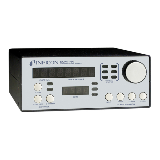
Page 41: Operation
SQM-160 Operating Manual Chapter 3 Operation 3.1 Introduction This chapter details the operation of the SQM-160 menus and front panel controls. 3.2 Front Panel Controls Figure 3-1 SQM-160 front panel Crystal Control Status Knob Display 1 Indicators Setpoint Configuration Control... - Page 42 SQM-160 Operating Manual Control Section Zero ......Press to zero the thickness reading. Xtal Life ..... . Press to toggle display between Crystal Life and Rate/Thickness readings.
-
Page 43: Menu Selection
In Program mode, Display 1 indicates the parameter to be changed. Display 2 indicates the value of the selected parameter. NOTE: If Crystal Life is displayed on SQM-160 display, press Xtal Life to return to normal Rate/Thickness or Frequency display. -
Page 44: Film Menu
SQM-160 Operating Manual 3.4 Film Menu The Film menu aids in programming SQM-160 for the materials that will be deposited. Ninety-nine films can be stored, but only one film is active at any time. Press Program to enter Program mode. -
Page 45: System Menu
SQM-160 Operating Manual Table 3-1 Film menu Display Description Range Default Units DENSITY Density of the material being deposited (see 0.50 to 99.99 1.00 g/cm Appendix A for common material densities). TOOLING Overall Tooling Factor for this film (see 10 to 399 section 3.8 on page... - Page 46 SQM-160 Operating Manual 3.5 System Menu The System menu sets function values for SQM-160 and the vacuum system setup. System menu parameters apply to all films. Press Program to enter Program mode. Press Prev to display the System menu. Press Next and Prev to select other parameters in the System menu.
- Page 47 SAMPLING When Sampling is ON, the sensor shutter On/Off periodically samples the rate, then closes the shutter. SQM-160 holds the same rate reading until the next sample period (see section 3.14 on page 3-14). Sample and Hold times are set in the Film menu (refer to section 3.4).
- Page 48 SQM-160 Operating Manual Table 3-2 System menu (continued) Display Description Range Default Units RELAYS Assigns normally open or normally closed nO/nC operation for each relay. NOTE: All relays are open with power FMIN/MAX Sub-menu sets minimum and maximum Min: 1.00 to 6.40 5.00...
-
Page 49: Sensor Selection
If the indicator is illuminated, the sensor is enabled and SQM-160 is receiving valid readings. If the indicator is blinking, the sensor is enabled, but SQM-160 is not receiving valid readings (crystal fail) (see Chapter 6, Troubleshooting and Maintenance). -
Page 50: Sensor Frequency
Both values are used to determine the % life that is displayed in Xtal Life mode. When the sensor frequency reads below the minimum or above the maximum, SQM-160 indicates a sensor failure (crystal fail) with a flashing Crystal Status indicator. To set sensor minimum and maximum frequencies: Press Program to enter Program mode. -
Page 51: Sensor Tooling
SQM-160 Operating Manual 3.8 Sensor Tooling Sensor Tooling (xTooling) adjusts for the difference in deposition rate between the sensor and the substrate being coated. It is an empirically determined value that aligns the sensor readings to the vacuum system. ... -
Page 52: Display Units
NOTE: The Display Units setting does not affect data returned through remote communications or analog outputs. 3.10 Crystal Life SQM-160 calculates the crystal life value based on the current frequency compared to the FMIN/FMAX values set in the System menu (refer to section 3.5 on page 3-6 section 3.7 on page... -
Page 53: Zero Thickness
3.13 Dual Sensors Dual sensors provide a backup (secondary) crystal should the primary crystal fail. When Relay 2 (RL2) is programmed for DUAL in the System menu, SQM-160 will automatically switch to Sensor 2 when Sensor 1 readings stop or become erratic. -
Page 54: Rate Sampling
With Rate Sampling enabled, SQM-160 opens a sensor shutter for a fixed time in order to sample the rate. SQM-160 then closes the shutter and for a fixed time. While the shutter is closed (Hold mode), SQM-160 calculates thickness based on the last sampled rate. -
Page 55: Time Setpoint
2 shutter relay. The function of Relay 2 is set in the System menu RL2 parameter (refer to section 3.5 on page 3-6 for more information about SQM-160 System parameters or see section 3.19 on page 3-18 for more information about SQM-160 relay functions). -
Page 56: Thickness Setpoint
SQM-160 Operating Manual 3.16 Thickness Setpoint The Time Setpoint provides a convenient way to signal a thickness based event when SAMPLING is set to OFF in the System menu. When the programmed thickness is reached, the Thick SP indicator illuminates and Relay 4 deactivates. -
Page 57: Simulate Mode
ON/OFF switch to ON or the procedure will not work. To clear only Film parameters: Press and hold ZERO + XTAL LIFE + SHUTTER while SQM-160 turns ON. Continue holding and proceed to step 2. To clear only System parameters (firmware version v4.10 and higher): Press and hold ZERO + XTAL LIFE + SHUTTER + CONTROL KNOB while SQM-160 turns ON. -
Page 58: Relay Operation
The four SQM-160 relays are physically single-pole, normally-open (1FormA) relays. Each relay can be programmed to act as either normally-open or normally-closed during SQM-160 operation. NOTE: All relays will open if SQM-160 is turned OFF or loses power (refer to section 2.5 on page 2-14 for relay wiring). -
Page 59: Depositing A Film
If the Program mode is active, press Program to return to Normal mode. Zero Thickness If needed, press Zero to zero the Thickness reading. Start Deposition Apply power to the source evaporation supply. If the SQM-160 shutter relay is connected (refer to section 2.5 on page 2-14), press Shutter to open the source shutter and begin deposition. - Page 60 SQM-160 Operating Manual This page is intentionally blank. 3 - 20...
-
Page 61: Introduction
SQM-160 Comm software communicates with SQM-160 to allow remote instrument setup and data logging. Features include: Selecting a Film on SQM-160, then opening the shutter to start deposition. Viewing SQM-160 readings in both numerical and graphical format. ... -
Page 62: Update Of An Older Version Of Sqm-160 Comm
If an older version of SQM-160 Comm software is being updated: Navigate to Windows Control Panel >> Programs. In Programs, select SQM-160 Comm and click Uninstall to remove the old version of SQM-160 Comm software. Install the latest version of SQM-160 Comm software (refer to section 4.2). -
Page 63: Start The Sqm-160 V2 Comm Software
For Windows 7 Click Windows Start icon >> All Programs >> INFICON >> SQM-160 Comm V2. Double click the SQM-160 Comm V2 shortcut icon on the desktop. For Windows 8 In the Start window, click the SQM-160 Comm V2 icon. -
Page 64: Main Window
4-1). Figure 4-1 SQM-160 Comm Main window - online On program startup, SQM-160 Comm software attempts to find an SQM-160 using the last communications port settings. It may take a few seconds to establish a connection. At this time, Initializing... will be displayed at the bottom of the Main window. -
Page 65: Menu Bar Functions
SQM-160 Operating Manual If SQM-160 Comm software is unable to connect to SQM-160, control functions are disabled, Off Line - Check communications is displayed at the bottom of the Main window, and Off Line is displayed at the top of the Main window (see Figure 4-2). -
Page 66: File Menu
Data Log ..... Opens the Data Log window for configuration of the SQM-160 Data Log function (see section 4.5 on page 4-9). -
Page 67: Edit Menu
Main window. 4.4.1.4 Help Menu About ......Displays the SQM-160 About window (see section 4.10 on page 4-23). -
Page 68: Main Window Control Functions
Zero ......Zeros the thickness reading on SQM-160. The following Main window features display readings from SQM-160: Graph &... -
Page 69: Data Log Window
4-7). 4.5 Data Log Window SQM-160 Comm software has the ability to log data to a .txt file at user-specified time intervals. Click File >> Data Log on the Main window to display the Data Log window. The Data Log window configures the SQM-160 Comm software data... -
Page 70: Log File Pane
SQM-160 Operating Manual Data is saved in tab delimited .txt file format for easy viewing or importing into a spreadsheet (see Table 4-1). Table 4-1 Data in tab delimited .txt file format Start: Date: 9/10/2013 Time: 14:04:41 Film: ALUM Time... -
Page 71: Duration Pane
Click Edit >> Films on the Main window to display the Films window. This window allows films to be created, edited, and saved to a file or transferred to/from SQM-160. The films are stored in an SQM-160 configuration file in an Extensible Markup Language (XML) format, Monitor.xml, in the SQM-160 Comm software program directory by default. - Page 72 .xml file. Upload Al <- ....Reads films stored in SQM-160 to the Films List and automatically saves the read films to the file UploadData.xml.
- Page 73 (closes the source shutter) and Final Thk indicator illuminates on the SQM-160 front panel. Values from 0 to 9999 kÅ are valid. Thick Setpoint....A thickness setpoint that closes the...
- Page 74 Material ..... . List of available materials. Materials named UnitMat# are unknown materials uploaded from SQM-160. Selecting a material in this list updates Density and Z factor parameters with stored values for that material.
-
Page 75: System Parameters Window
Click Edit >> System on the Main window to display the System Parameters window. This window allows system parameters to be sent to or read from a connected SQM-160. These parameters appear in the SQM-160 System menu (refer to section 3.5 on page 3-6). - Page 76 SQM-160. This option only affects the number of displayed digits. Display Thickness ... . . When selected, DSP on the SQM-160 System menu is set to THCK. If DSP is set to NANM, FREQ, or MASS, Display Thickness is cleared.
-
Page 77: Communications Setup Window
3.5 on page 3-6). USB ......Select the connected SQM-160 (for example, 91102). 4 - 17... -
Page 78: Establishing Communications
(for example, Port 2101, Address 192.168.1.200). Close ......Exits SQM-160 Comm Setup window and saves communications settings. - Page 79 Verify SQM-160 is turned on and connected to the computer with a standard USB cable. Select USB in the Comm Port pane of the SQM-160 Comm Setup window. Click Find to test the connection. If communication is established successfully, Found SQM-160 Ver.
-
Page 80: Command Field
SQM-160 Operating Manual 4.8.2 Command Field In the SQM-160 Comm Setup window, the Command field provides a command/response interface for testing SQM-160 remote commands (see Figure 4-7). The remote communications protocol and commands are detailed in section 5.3, SQM-160 Communications Protocol, on page 5-9. -
Page 81: Configure Graph(S) Window
SQM-160 Operating Manual 4.9 Configure Graph(s) Window Click Edit >> Graph Settings on the Main window to display the Configure Graph(s) window. This provides access to graph axis and grid settings. Figure 4-8 Configure Graph(s) window OK ......Click to save changes and exit the Configure Graph(s) window. - Page 82 SQM-160 Operating Manual The following are available on the Avg Rate, Sensor Rate, Avg Thickness, and Sensor Thickness tabs. Y Axis Range Y Axis Min ....Sets the minimum value displayed on the Y axis of the graph, in Å/s or kÅ...
-
Page 83: Help Menu
SQM-160 Operating Manual 4.10 Help Menu Click Help >> About on the Main window to display the About window, which provides program revision installation information (see Figure 4-9). Figure 4-9 About window NOTE: Help >> Help does not have an assigned function. - Page 84 SQM-160 Operating Manual This page is intentionally blank. 4 - 24...
-
Page 85: Introduction
2-11). A mating male connector is required to attach a host interface. The host and SQM-160 can be separated by up to 15.2 m (50 ft.) using multiconductor shielded data cable. For successful communications, the baud rate of the host and SQM-160 must match. -
Page 86: Usb Port
Once the drivers are installed, Windows will find and install SQM-160 automatically when connected to a USB port. NOTE: If SQM-160 is not found, it is possible to manually install the device from the 074-5000-G1 INFICON Thin Film Instrument and Sensor Manuals CD using the USB Installer v1.8.0 Setup file. -
Page 87: Accessing Network Settings In Windows Xp
SQM-160 Operating Manual SQM-160 ships with a pre-assigned address of 192.168.1.200. To communicate directly with SQM-160 from a computer, the computer must also be assigned a 192.168.1.xxx address, but cannot be set to 192.168.1.200. The examples in section 5.1.3.1.1 section 5.1.3.1.2 use the address 192.168.1.201 for the... - Page 88 SQM-160 Operating Manual On the General tab, select Internet Protocol (TCP/IP) and click the Properties button (see Figure 5-3). Figure 5-3 Internet Protocol (TCP/IP) Properties 5 - 4...
- Page 89 Figure 5-4 Entering the IP Address and Subnet mask Click OK in all open dialog boxes to close out the Internet Protocol setup for the Local Area Connection. Open the SQM-160 software and confirm communications (refer to section 4.8 on page 4-17).
-
Page 90: Accessing Network Settings In Windows 7 And Windows 8
SQM-160 Operating Manual 5.1.3.1.2 Accessing Network Settings in Windows 7 and Windows 8 Open the Control Panel (Start >> Control Panel) and Select Network and Sharing Center. Click Change adapter settings on the left side panel (see Figure 5-5). This will open the Network Connections window. - Page 91 SQM-160 Operating Manual In the Local Area Connection Properties, select Internet Protocol Version 4 (TCP/IPv4) and click Properties (see Figure 5-7). Figure 5-7 Local Area Connection Properties 5 - 7...
-
Page 92: How To Change The Sqm-160 Ip Address
Figure 5-8) and click OK. With this selection, the computer is assigned an IP address to use when communicating with SQM-160. Figure 5-8 Entering the IP Address and Subnet mask Click OK in all open dialog boxes to exit the Internet Protocol setup for the Local Area Connection. -
Page 93: Comm Software
SQM-160 communicates with a host computer using an ASCII based protocol. SQM-160 defaults to 19,200 baud, 8 data bits, and no parity. The baud rate can be changed in the SQM-160 System menu, but is always 8 data bits with no parity. -
Page 94: Response Packet (Sqm-160 To Host Message)
SQM-160 Operating Manual 5.3.2 Response Packet (SQM-160 to Host Message) <Sync character><Length character><Response Status character><Response Message><CRC1><CRC2> Sync......The Sync character is an exclamation point (!). -
Page 95: Calculating The Crc
SQM-160 Operating Manual 5.3.3 Calculating the CRC The following algorithm is used to compute the Cyclic Redundancy Check (CRC): NOTE: The Sync character and CRC are not included in the CRC calculation. All other characters should be included. The CRC register (16 bits) is initialized to hexadecimal 3FFF. -
Page 96: Commands
SQM-160. Update ..... . . Updates parameters in SQM-160. Remote ..... . Performs an action. -
Page 97: Command
SQM-160 Operating Manual 5.4.1 Command: @ Command Type ....Query Description ....Returns the firmware version number. - Page 98 SQM-160 Operating Manual Thickness Setpoint ... 0.000 to 9999 (kÅ) Time Setpoint ....0:00 to 99:59 (mm:ss) Sent/received in integer seconds (0 to 5999).
-
Page 99: Command: B
SQM-160 Operating Manual 5.4.3 Command: B Command Type ....Query/Update Description ....Query or update System 1 parameters. -
Page 100: Command: C
SQM-160 Operating Manual Example (query) Sent ..... . !$B?(93)(116) Received ....!JA_0.10_1_0_0_1_100_100_100_100_100_... -
Page 101: Command: D
SQM-160 Operating Manual 5.4.5 Command: D Command Type ....Update Description ....Update the active Film. -
Page 102: Command: M
SQM-160 Operating Manual 5.4.8 Command: M Command Type ....Status Description ....Read the current Average Rate. -
Page 103: Command: P
SQM-160 Operating Manual 5.4.11 Command: P Command Type ....Status Description ....Read the current Frequency for a sensor. -
Page 104: Command: T
SQM-160 Operating Manual 5.4.14 Command: T Command Type ....Remote Description ....Zero Time Command Structure . -
Page 105: Command: Y
Description ....Read the status of the Power-Up Reset flag. The Power-Up Reset flag is set while SQM-160 turns on, and stays set until the status of the RS-232 interface is read. After the flag is read, it is reset and will not be set again until SQM-160 is power cycled. -
Page 106: Crc Examples
SQM-160 Operating Manual 5.5 CRC Examples This section includes examples of code for calculating the CRC in Visual Basic, Java, and C++. Instructions for calculating the CRC are located in section 5.3.3 on page 5-11. ® 5.5.1 Visual Basic Public Sub CalcChkSumByte(ByRef ByData() As Byte, ByRef byCRC() As... - Page 107 SQM-160 Operating Manual Public Function LoByte(ByVal intNumber As Integer) As Byte ' Comments : Returns the low byte of the passed integer ' Parameters: intNumber - integer value for which to return the low byte ' Returns : byte ' Source...
-
Page 108: Java
SQM-160 Operating Manual PROC_ERR: MsgBox "Error: " & Err.Number & ". " & Err.Description, , _ "Shri" Resume PROC_EXIT End Function ® 5.5.2 Java private short calcCRC(byte[] str) { short crc = 0; short tmpCRC; int length = 1 + str[1] - 34;... - Page 109 SQM-160 Operating Manual 5.5.3 C++ class CRC14 public: CRC14(void) { crc = 0x0;}; public: short crc; public: short calcCRC( unsigned char * str) int length = (str != NULL) ? 1 + str[1] - 34 : 0; if (length > 0) { crc = (short) 0x3fff;...
- Page 110 SQM-160 Operating Manual This page is intentionally blank. 5 - 26...
-
Page 111: Troubleshooting And Maintenance
Chapter 6 Troubleshooting and Maintenance 6.1 Troubleshooting Guide If SQM-160 does not function as expected, or appears to have diminished performance, the following Symptom/Cause/Remedy chart may be helpful (see Table 6-1). Additional troubleshooting information can be found in the operating manuals for sensors, located on the Thin Film Instrument and Sensor Manuals CD. - Page 112 Ground wires or straps must connect to an appropriate earth ground (refer to section 2.1 on page 2-1). SQM-160 is malfunctioning. Contact INFICON service department (refer to section 1.3 on page 1-4). Stored parameter values SQM-160 is malfunctioning. Contact INFICON service are lost when SQM-160 is department.
- Page 113 SQM-160 Operating Manual Table 6-1 Symptom/Cause/Remedy chart (continued) SYMPTOM CAUSE REMEDY Thickness, Frequency, or Humidity level on the crystal Avoid condensation by Mass reading is unstable is changing. Moisture being turning off cooling water to or drifting (not the absorbed or exuded from the...
- Page 114 SQM-160 Operating Manual Table 6-1 Symptom/Cause/Remedy chart (continued) SYMPTOM CAUSE REMEDY Thickness, Frequency, or SQM-160 or oscillator is Test the SQM-160 and Mass reading is unstable malfunctioning. oscillator using the oscillator or drifting (not the test mode (see section 6.4 on...
- Page 115 SQM-160 Operating Manual Table 6-1 Symptom/Cause/Remedy chart (continued) SYMPTOM CAUSE REMEDY Crystal Status indicator is Failed crystal, or no crystal in Install a new crystal. blinking, indicating Xtal sensor. fail. Two crystals were installed or Remove extra crystal. crystal is upside down.
- Page 116 Substitute a known good in-vacuum cable. Substitute a known good sensor/feedthrough. Substitute a PN 760-601-G2 Sensor Emulator for the sensor. SQM-160 or oscillator is Test the SQM-160 and malfunctioning. oscillator using the oscillator test mode (see section 6.4 on page 6-13).
- Page 117 SQM-160 Operating Manual Table 6-1 Symptom/Cause/Remedy chart (continued) SYMPTOM CAUSE REMEDY Crystal Status indicator is Crystal is being hit by small Use a shutter to shield the blinking, indicating Xtal droplets of molten material sensor during source fail, during deposition from the evaporation source.
- Page 118 SQM-160 Operating Manual Table 6-1 Symptom/Cause/Remedy chart (continued) SYMPTOM CAUSE REMEDY Rate reading, and Excessive cable length In-vacuum cable length Thickness, Frequency, or between oscillator and should not exceed 78.1 cm Mass reading are noisy. crystal. (30.75 in.). Use the 15.2 cm (6 in.) cable between oscillator and feedthrough.
- Page 119 SQM-160 Operating Manual Table 6-1 Symptom/Cause/Remedy chart (continued) SYMPTOM CAUSE REMEDY Thickness, Frequency, or Mode hopping due to Replace the crystal. Mass reading has large damaged crystal. excursions during Crystal is near the end of its Replace the crystal. deposition.
- Page 120 SQM-160 Operating Manual Table 6-1 Symptom/Cause/Remedy chart (continued) SYMPTOM CAUSE REMEDY Thickness, Frequency, or Excessive heat input to the If heat is due to radiation Mass reading has large crystal. from the evaporation source, excursions during source move sensor farther away (at warm-up or when source least 25.4 cm (10 in.)) from...
- Page 121 Check cable connections. established between the connected properly to host computer and SQM-160 or host computer. SQM-160. Baud setting in SQM-160 is Correct communications port different than the baud settings (refer to section 3.5 setting in SQM-160 Comm on page 3-6 section 4.8...
-
Page 122: Maintenance
6.2 Maintenance Routine maintenance is not required for SQM-160. Regular sensor maintenance procedures should be followed according to the sensor operating manual. 6.3 Spare Parts Fuse ......PN 062-0105 Oscillator . -
Page 123: Persistent Crystal Fail Indication
This connects the internal test crystal to the circuit instead of the normal Sensor connector. If SQM-160 and the oscillator are functioning correctly, the Crystal Status indicator will stop blinking and illuminate while this button is depressed. - Page 124 SQM-160 Operating Manual This page is intentionally blank. 6 - 14...
-
Page 125: Calibration Procedures
7.1 Importance of Density, Tooling and Z-Ratio The quartz crystal microbalance is capable of precisely measuring the mass added to the face of the oscillating quartz crystal sensor. SQM-160 recognizes the density of this added material to allow conversion of the mass information into thickness. -
Page 126: Determining Tooling
Thickness reading on SQM-160 Measured thickness A quick check of the calculated Density may be made. If the SQM-160 thickness has not been zeroed between the test deposition, enter the calculated Density. Program SQM-160 with the new Density value and observe whether the displayed thickness is equal to the measured thickness. -
Page 127: Laboratory Determination Of Z-Ratio
SQM-160 Operating Manual 7.4 Laboratory Determination of Z-Ratio A list of Z-Ratio values for materials commonly used are available in Appendix For other materials, Z-Ratio can be calculated from the following formula: -- - ----------- - ... - Page 128 SQM-160 Operating Manual Using the Density value from step 1 and the recorded values for F and F adjust the Z-Ratio value in thickness equation [5] to bring the calculated thickness value into agreement with the actual thickness. If the calculated value of thickness is greater than the actual thickness, increase the Z-Ratio value.
-
Page 129: Measurement And Theory
SQM-160 Operating Manual Chapter 8 Measurement and Theory 8.1 Basics The Quartz Crystal deposition Monitor (QCM) utilizes the piezoelectric sensitivity of a quartz monitor crystal to added mass. The QCM uses this mass sensitivity to control the deposition rate and final thickness of a vacuum deposition. -
Page 130: Monitor Crystals
SQM-160 Operating Manual A crystal with a starting frequency of 6.0 MHz will display a reduction of its frequency by 2.27 Hz when 1 angstrom of Aluminum (density of 2.77 g/cm is added to its surface. In this manner, the thickness of a rigid adlayer is inferred from the precise measurement of the frequency shift of the crystal. - Page 131 SQM-160 Operating Manual The second set of improvements was to contour one face of the crystal and to reduce the size of the exciting electrode. These improvements have the effect of trapping the acoustic energy. Reducing the electrode diameter limits the excitation to the central area.
-
Page 132: Period Measurement Technique
SQM-160 Operating Manual Since there is currently no way to separate the frequency change caused by added mass (which is negative), or even the frequency changes caused by temperature gradients across the crystal or film induced stresses, it is essential to minimize these temperature-induced changes. - Page 133 SQM-160 Operating Manual Electronically, the period measurement technique uses a second crystal oscillator, or reference oscillator, not affected by the deposition, which is usually much higher in frequency than the monitor crystal. This reference oscillator is used to generate small precision time intervals, which are used to determine the oscillation period of the monitor crystal.
-
Page 134: Z-Match Technique
SQM-160 Operating Manual 8.1.3 Z-match Technique After learning of fundamental work by Miller and Bolef , which rigorously treated the resonating quartz and deposited film system as a one-dimensional continuous acoustic resonator, Lu and Lewis developed the simplifying Z-match™ equation in 1972. -
Page 135: Material Table
SQM-160 Operating Manual Appendix A Material Table A.1 Introduction The following Table A-1 represents the density and Z-Ratio for various materials. The list is alphabetical, by chemical formula. WARNING Some of these materials are toxic. Consult the material safety data sheet and safety instructions before use. - Page 136 SQM-160 Operating Manual Table A-1 Material table (continued) Formula Density Z-Ratio Material Name 5.720 *1.000 barium oxide BaTiO 5.999 0.464 barium titanate (tetr) BaTiO 6.035 0.412 barium titanate (cubic) 1.850 0.543 beryllium 1.990 *1.000 beryllium fluoride 3.010 *1.000 beryllium oxide 9.800...
- Page 137 SQM-160 Operating Manual Table A-1 Material table (continued) Formula Density Z-Ratio Material Name 7.200 0.305 chromium 5.210 *1.000 chromium (iii) oxide 6.680 *1.000 chromium carbide 6.170 *1.000 chromium boride 1.870 *1.000 cesium 4.243 1.212 cesium sulfate CsBr 4.456 1.410 cesium bromide CsCI 3.988...
- Page 138 SQM-160 Operating Manual Table A-1 Material table (continued) Formula Density Z-Ratio Material Name 5.200 *1.000 germanium nitride 6.240 *1.000 germanium oxide GeTe 6.200 *1.000 germanium telluride 13.090 0.360 hafnium 10.500 *1.000 hafnium boride 12.200 *1.000 hafnium carbide 13.800 *1.000 hafnium nitride 9.680...
- Page 139 SQM-160 Operating Manual Table A-1 Material table (continued) Formula Density Z-Ratio Material Name 9.840 *1.000 lutetium 1.740 1.610 magnesium MgAl 3.600 *1.000 magnesium aluminate MgAl 8.000 *1.000 spinel 3.180 0.637 magnesium fluoride 3.580 0.411 magnesium oxide 7.200 0.377 manganese 5.390 0.467...
- Page 140 SQM-160 Operating Manual Table A-1 Material table (continued) Formula Density Z-Ratio Material Name NiCrFe 8.500 *1.000 Inconel NiFe 8.700 *1.000 permalloy NiFeMo 8.900 *1.000 supermalloy 7.450 *1.000 nickel oxide 2.510 *1.000 phosphorus nitride 11.300 1.130 lead PbCl 5.850 *1.000 lead chloride 8.240...
- Page 141 SQM-160 Operating Manual Table A-1 Material table (continued) Formula Density Z-Ratio Material Name 2.320 0.712 silicon 3.440 *1.000 silicon nitride 3.220 *1.000 silicon carbide 2.130 0.870 silicon (ii) oxide 2.648 1.000 silicon dioxide 7.540 0.890 samarium 7.430 *1.000 samarium oxide 7.300...
- Page 142 SQM-160 Operating Manual Table A-1 Material table (continued) Formula Density Z-Ratio Material Name 4.900 *1.000 titanium oxide 4.260 0.400 titanium (iv) oxide 11.850 1.550 thallium TIBr 7.560 *1.000 thallium bromide TICI 7.000 *1.000 thallium chloride 7.090 *1.000 thallium iodide (b) 19.050...
- Page 143 SQM-160 Operating Manual Table A-1 Material table (continued) Formula Density Z-Ratio Material Name 6.490 0.600 zirconium 6.080 *1.000 zirconium boride 6.730 0.264 zirconium carbide 7.090 *1.000 zirconium nitride 5.600 *1.000 zirconium oxide A - 9...
- Page 144 SQM-160 Operating Manual This page is intentionally blank. A - 10...
Need help?
Do you have a question about the SQM-160 and is the answer not in the manual?
Questions and answers