Table of Contents
Advertisement
Advertisement
Table of Contents
Troubleshooting

Related Manuals for Calix T073G HGU ONT


Summary of Contents for Calix T073G HGU ONT
-
Page 1: User Guide
User Guide T073G HGU ONT 220-00602 Rev 10... - Page 2 Copyright © Calix. All rights reserved. No part of this document may be reproduced in any form without the written permission of the copyright owner. Disclaimer The contents of this document are subject to revision without notice due to continued progress in methodology, design, and manufacturing. Calix shall have no liability for any error or damage of any kind resulting from the use of this document.
-
Page 3: Table Of Contents
Contents Contents Product Description Introduction Services Features Specifications Safety Electrical Safety Laser Safety Installation Get to Know the ONT Connecting to the PON Network Connecting Power Connecting Telephone (POTS) Service Connecting Ethernet Service Verifying the Installation Troubleshooting ONT Status LEDs Troubleshooting Procedures 220-00602 R10 | October, 2013... - Page 4 User Guide 220-00602 R10 | October, 2013...
-
Page 5: Product Description
Product Description Product Description Introduction The T073G Optical Network Terminal (ONT) is an ITU-T G.984 compliant device that receives voice, data, and video traffic in the form of optical signal from the service provider Passive Optical Network (PON) and transmitted it to the desired format at residential or business premises. -
Page 6: Specifications
User Guide Specifications Table 1 lists the physical specification. Table 2 lists the electrical specification. Table 3 lists the environmental specification. Table 4 lists the optical specification. Table 1 Physical Specifications Dimensions • Height: 47 mm (1.85 inch) • Width: 229 mm (9 inch) •... - Page 7 Product Description Minimum Nominal Maximum Notes Sensitivity -27 dBm Minimum received power BER<10 Overload -8 dBm Maximum received power for BER<10 220-00602 R10 | October, 2013...
-
Page 8: Safety
User Guide Safety Read and follow all warning notices and instructions marked on the product or included in its packaging, and observe all safety instructions listed in this guide while handling any ONT. Electrical Safety • Always use caution when handling live electrical connections. •... - Page 9 Safety Danger! Personnel handling fiber optic cables must be trained for laser safety. Caution! Do not bend the fiber optic cable to a diameter smaller than 7.5 cm (3 inches). Doing so may damage the fiber or prevent the signal from passing through properly.
-
Page 10: Installation
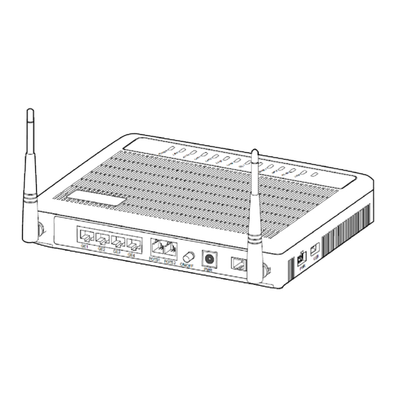
User Guide Installation Get to Know the ONT The figures below show the overview of the ONT. USB connector Ethernet ports POTS ports UPS connector Power switch DC power connector G102382A Figure 1 T073G Back and Right-Side Overview WLAN RESET G102296A Figure 2 T073G Left-Side Overview... -
Page 11: Connecting Power
Installation 2. Remove the dust covers from the SC/APC optical connector. Clean the connectors if necessary. G102342A 3. Plug in the fiber connector to connect the ONT to the network. G102343A Connecting Power The T073G can be powered by the AC power adapter or by an UPS power. This section describes how to power the ONT by both. - Page 12 3.3.2 Connecting to an External UPS NOTE: UPS power cord is sold separately. It is not included with this package. Please contact Calix customer support for information. G102409A Figure 3 UPS PIN Numbering Table 5...
-
Page 13: Connecting Telephone (Pots) Service
Installation Color Signal Description Green Unused Black/Brown Power ground/Signal ground Purple REPLACE_BAT Replace battery Orange LOW_BAT Low battery Yellow Unused Connecting Telephone (POTS) Service 1. Locate the telephone wire pair of premise. 2. If the wire pair is not terminated, follow local practices to attach an RJ-11 connector 3. -
Page 14: Verifying The Installation
User Guide Table 7 Ethernet RJ-45 Connector Wiring Pattern Color Signal Color Signal Orange/White TX_D1+ Blue/White BI_D3- Orange TX_D1- Green RX_D2- Green/White RX_D2+ Brown/White BI_D4+ Blue BI_D3+ Brown BI_D4- Verifying the Installation Check LED states to verify ONT status. Services are not available until the ONT is ranged and provisioned in the PON network. - Page 15 Installation • Verify that the AUTH LED light is green, indicating that the ONT is operating normally. The ONT is placed into service remotely through the OLT. Services to the ONT are likewise provisioned and turned up remotely through the PON network. •...
-
Page 16: Troubleshooting
User Guide Troubleshooting ONT Status LEDs The ONT status LEDs assist with installation and maintenance procedures. These LEDs are described in Table 8. G102381A Figure 6 ONT Status LEDs location Table 8 T073G LED Description Indication Color Status POWER Green Solid ONT is operating from AC power Slow Blink ONT is operating from UPS power... -
Page 17: Troubleshooting Procedures
Troubleshooting Indication Color Status TEL1/2 Green Solid Already register to soft-switch, but no service flow and the line is on-hook Blink There is service flow on this port or the telephone is off-hook System power is off, or is not registered to soft-switch Internet Green... -
Page 18: R10 | October
User Guide Table 9 Troubleshoot Procedures Problem Procedure The POWER LED is off • Check whether the Power Switch button on the rear of the ONT is pressed • Check whether the power adapter matches the ONT • Check whether the power connection is correct The LINK LED is off •... -
Page 19: Fcc Statement
FCC statement ·This device complies with part 15 of the FCC Rules. Operation is subject to the following two conditions: (1) This device may not cause harmful interference, and (2) this device must accept any interference received, including interference that may cause undesired operation. - Page 20 RF exposure warning · This equipment must be installed and operated in accordance with provided instructions and the antenna(s) used for this transmitter must be installed to provide a separation distance of at least 20 cm from all persons and must not be co-located or operating in conjunction with any other antenna or transmitter.
Need help?
Do you have a question about the T073G HGU ONT and is the answer not in the manual?
Questions and answers