
Related Manuals for Cohu HD 4260HD


Summary of Contents for Cohu HD 4260HD
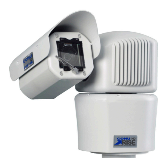
- Page 1 RISE™ Series 4260HD Camera Positioning System Installation Manual 6x-1114D www.CohuHD.com...
- Page 2 - 2 -...
-
Page 3: Table Of Contents
3.3.6 Interconnection Diagram with 120 Vac Power Supply. MS or AMP Connectors 3.3.7 Power over Ethernet (PoE++) 3.4 4260HD Cables 3.4.1 4260HD Models and Available Cable Functions 3.4.2 RJ-45 Connector Pinouts (Models 4261HD, 4262HD, and 4263HD) 3.4.3 RJ-45 Connector Pinouts (Models 4264HD, 4265HD, 4266HD, 4268HD, and 4269HD) 3.4.4 18-pin MS Type (Metal) Connector and its Mating System Cable Connector (Models 4263HD,... - Page 4 3.6.1 Large Pedestal Adapter for the PoE and 24 Vac Power Option 3.6.2 Large Pedestal Plate for the 120 Vac Power Option 3.6.3 Wall Mount Installation 3.6.4 Pole Mount Installation 3.6.5 Corner Mount Installation 3.6.6 Parapet Mount Installation 3.7 Installation Procedure 3.7.1 Instructions on How to Assemble the Waterproof Shielded RJ45 Coupler 3.8 Overall Dimensions and Mounting Base Hole Pattern 3.9 Mounting Brackets Dimensions...
-
Page 5: General Information
1.0 General Information 1.1 About this document This document contains information on how to install and maintain the 4260HD Series Camera Positioning System.Please read this manual carefully prior to installation to prevent any accidental damage or misuse. The manual is available from the CohuHD website at http://www.cohuhd.com/Support/Product-Documentation... -
Page 6: Shipment
If a visual inspection shows damage upon receipt of this shipment, it must be noted on the freight bill or express receipt and the notation signed by the carrier’s agent. Failure to do this can result in the carrier refus- ing to honor the claim. -
Page 7: Safety Instructions
2.0 Safety Instructions 2.1 Important Information Warning: Do not remove the covers or housing. There are no user-serviceable parts inside. Warning: The Schrader Valves on the camera head's back plate are for factory use only. Do not attempt to add any gas to the camera head. Warning: PoE++ (Power over Ethernet) injectors used with this camera system may operate from 100-240 Vac. - Page 8 camera must be bonded to the pole. For installation on a non-grounded or insulated support, the cam- era must be grounded with an adequate ground strap or wire between the camera and a nearby ground system, or to a ground system installed at the base of the support. Failure to adequately ground the camera may lead to failure of the camera.
-
Page 9: Installation
3.0 Installation 3.1 4260 Camera Positioner System Overview The 4260 Camera System is an IP camera system contained within three independently sealed and envi- ronmentally protected sections. The camera system provides IP video streams with H.264 and MJPEG com- pression. The positioning system provides continuous 360° pan (azimuth) motion range with +/- 95° of tilt (elevation). - Page 10 Cables See "4260HD CohuHD- Manufactured System Cables " on page 23. PoE ++ Injectors CohuHD p/n 7412007-001, 120 Vac CohuHD p/n 7412007-002, 230 Vac CohuHD p/n 7412007-003, See "Power over Ethernet (PoE++)" on page 14 . Field Connectors MS Mating Connector: Amphenol p/n PT06E-14-18S(476) or equivalent, CohuHD p/n 1310230-111.
-
Page 11: 4260Hd Interconnection Diagrams
See "Safety Instructions" on page 7. See " Installation Procedure" on page 33 for the camera grounding pro- cedure. The following are interconnection diagrams for the 4260HD camera system: 3.3.1 Interconnection Diagram with PoE++ Power Supply and Non-PoE Switch. 3.3.2 Interconnection Diagram with PoE++ Power Supply, I/O and Non-PoE Switch. -
Page 12: Interconnection Diagram With 24 Vac Power Supply, Analog And Ip Output
3.3.3 Interconnection Diagram with 24 Vac Power Supply, Analog and IP Output. 3.3.4 Interconnection Diagram with 24 Vac Power Supply, Analog and IP Output. - 12 -... -
Page 13: Interconnection Diagram With 120 Vac Power Supply
3.3.5 Interconnection Diagram with 120 Vac Power Supply. 3.3.6 Interconnection Diagram with 120 Vac Power Supply. MS or AMP Connectors - 13 -... -
Page 14: Power Over Ethernet (Poe++)
Midspan PoE++: Power is supplied by an injector placed between an existing non-PoE++ switch and the camera. PoE++ injectors can be ordered from CohuHD. Please refer to the CohuHD website in the 4260HD series specifications section for ordering information. The PoE++ injector selected for use with 4260HD must meet the following requirement: Be compatible with the LTPoE++ specification. -
Page 15: 4260Hd Cables
3.4.1 4260HD Models and Available Cable Functions The 4260HD camera system is built with one or two cables attached to the camera base for electrical con- nection. The 4260HD camera model number identifies the type(s) of cable(s) the camera system requires. -
Page 16: Connector Pinouts (Models 4261Hd, 4262Hd, And 4263Hd)
3.4.2 RJ-45 Connector Pinouts (Models 4261HD, 4262HD, and 4263HD) RJ-45 Connector Pin Function Ethernet TX+ Ethernet TX- Ethernet RX+ Ethernet RX- PoE++ VPort- PoE++ VPort+ PoE++ VPort+ PoE++ VPort- 3.4.3 RJ-45 Connector Pinouts (Models 4264HD, 4265HD, 4266HD, 4268HD, and 4269HD) RJ-45 Connector Function Ethernet TX+... -
Page 17: Ms Connector Pinouts (Models 4263Hd And 4265Hd)
3.4.4.1 MS Connector Pinouts (Models 4263HD and 4265HD) MS Connector Function DIO 1 DIO 3 DIO 2 I/O Common RS422 RX+ RS422 RX- RS422 TX+ RS422 TX- Analog Video Output Analog Video Shield Not Connected Not Connected Not Connected 24 Vac Not Connected Not Connected 24 Vac... -
Page 18: Ms Connector Pinouts (Model 4267Hd)
3.4.4.3 MS Connector Pinouts (Model 4267HD) MS Connector Function DIO 1 DIO 3 DIO 2 I/O Common RS422 RX+ RS422 RX- RS422 TX+ RS422 TX- Analog Video Output Analog Video Shield 120 Vac Line Ethernet RX- Ethernet TX+ Not Connected Ethernet TX- Ethernet RX+ 120 Vac Neutral... -
Page 19: Stripped Leads Wire Colors And Corresponding Functions (Models 4262Hd And 4264Hd)
3.4.5 Stripped Leads Wire Colors and Corresponding Functions (Models 4262HD and 4264HD) Stripped Leads Wire Color Function DIO 1 WHT/BLK DIO 2 RED/GRN DIO 3 DIO 4 Factory Default I/O Common WHT (26 AWG) RS422 RX+ BLK (26 AWG) RS422 RX- RS422 TX+ RS422 TX- COAX CENTER (WHT) -
Page 20: Amp Connector Pinouts (Model 4269Hd)
3.4.6.1 Amp Connector Pinouts (Model 4269HD) AMP Connector Function Analog Video Output Analog Video Shield I/O Common RS422 TX- RS422 TX+ RS422 RX+ RS422 RX- Not Connected Not Connected Not Connected Not Connected 120 Vac Line 120 Vac Neutral Overall Shield AC Ground Not Connected 3.4.7 Digital Inputs/Outputs (DIO) -
Page 21: Field Cables
3.4.8 Field Cables All system cables must be shielded, and the shield(s) must be bonded to earth ground. All Ethernet wiring must be done in accordance with TIA/EIA 568-C standards. To build the camera system cables, CohuHD recommends: For Ethernet/PoE++: Belden p/n 7919A Multi-Conductor - Category 5e DataTuff® Twisted Pair Cable,overall Beldfoil shield (100% coverage). - Page 22 For Power: Two wires, insulated for 300 V minimum, 18 AWG cord for power. Use for distances up to 80 feet (29 m) for 24 Vac cables. Note: Long cable lengths and/or low mains voltages can cause the 24 Vac power at the camera to drop below the minimum input voltage (24 Vac -10%) resulting in unreliable operation.
-
Page 23: 4260Hd Cohuhd- Manufactured System Cables
Note: The symbol "-" means that the cable is incompatible with the camera model. Warning: Connecting certain cables to the 4260HD Series camera systems can result in permanent damage to the camera. Do not connect any cable to a 4260HD camera system without verifying com- patibility first. -
Page 24: 4266Hd Cable Compatibility
3.4.9.1 4266 Cable Compatibility The 4266 camera system is designed to be compatible with many existing field cables for 24 Vac systems, and with a power conversion junction box for 120 Vac systems. If the 4266 camera system is intended to be a replacement for an existing 3964, 3965, HD34 or HD35 camera systems, it is probable that the existing cable can be used, eliminating the need to pull new cable to an existing site. - Page 25 CA255A, B, C, D: Potential Hazard: No Supports: Ethernet Does Not Support: PoE Power, Analog Video, Alarm I/O, Relay I/O, Serial Communication CA255M, R, S, T: Relay I/O is being used Potential Hazard: Yes Do Not Connect to 4266 CA255M, R, S, T: Relay I/O is not being used Potential Hazard: No Supports: Ethernet, Analog Video, Alarm 1, RS422 Communication Does Not Support: PoE Power, Alarm 2, 3, 4, Relay I/O...
- Page 26 CA292 (All): Not Compatible Potential Hazard: Yes Do Not Connect to 4266 CA293 (All): Not Compatible Potential Hazard: Yes Do Not Connect to 4266 CA295 (All): Compatible Potential Hazard: No Requires: 4266 Junction box to convert 120 Vac to 24 Vac Supports: Analog Video, RS422 Communication Does Not Support: Ethernet, PoE Power, Alarm I/O, Relay I/O CA296 (All): Not Compatible...
-
Page 27: 4260Hd Camera System Mounting Methods
3.5 4260 Camera System Mounting Methods 3.5.1 Standard and Inverted Mounting Methods The 4260 camera system is available in the following mount configurations: Standard Inverted 3.5.1.1 Inverted Mount Configuration When installed in the inverted position, the camera orientation and control functions are reconfigured through the software via browser interface. - Page 28 The following mounts are recommended by CohuHD and can be purchased with the 4260 camera system: Large Pedestal Plate: CohuHD p/n 8481-9 The kit includes: Large Plate: CohuHD p/n 8481908-001 Large Pedestal Adapter: CohuHD p/n7411444-003 Wall mount: CohuHD p/n 8425-7 The kit includes: Wall mount: CohuHD p/n 7411417-001 Mount adapter: CohuHD p/n 7411418-001...
-
Page 29: 4260Hd Camera System Mounting Diagrams
3.6 4260 Camera System Mounting Diagrams 3.6.1 Large Pedestal Adapter for the PoE and 24 Vac Power Option Use the large pedestal adapter for additional mounting hole patterns. See "Large Pedestal Adapter" on page 3.6.2 Large Pedestal Plate for the 120 Vac Power Option Use the large pedestal plate for additional mounting hole patterns. -
Page 30: Wall Mount Installation
3.6.3 Wall Mount Installation Use the mount adapter and wall mount for installation to a wall. See "Wall Mount" on page 39. 3.6.4 Pole Mount Installation Use the mount adapter, wall mount, and large pole mount for installation to a pole. See "Pole Mount" on page 39. - 30 -... -
Page 31: Corner Mount Installation
3.6.5 Corner Mount Installation Use the mount adapter, wall mount, and large corner mount for installation to a corner. See "Corner Mount" on page 40. 3.6.6 Parapet Mount Installation Use the mount adapter, wall mount, and parapet mount for installation to a parapet. See "Parapet Mount" on page 40. - Page 32 The parapet mount: Installs on the inside of a parapet that is at least 18 inches (457.2 mm) high. Is rotatable 360° so the camera positioner system can be installed from the roof. - 32 -...
-
Page 33: Installation Procedure
3.7 Installation Procedure Warning: The camera is top heavy and may tip over if not supported. Always support a camera until it has been fastened securely. Caution: Do not use the cable to support the weight of the camera. Provisions must be made for routing the system cable up to the camera system location: Pole: If the cable routes up through the pole, support the cable inside the pole to strain relieve the cam- era connector. - Page 34 Install the camera system: Position the camera on the mount adapter/plate or pedestal and secure it with the 1/4-inch fas- teners (supplied). Note: For easy installation, look for two alignment marks on the base housing for hole loca- tion. Applies to 4261HD - 4266HD. Ground the camera: Connect the grounding wire to the grounding screw on the camera's base.
-
Page 35: Instructions On How To Assemble The Waterproof Shielded Rj45 Coupler
3.7.1 Instructions on How to Assemble the Waterproof Shielded RJ45 Coupler To connect two outdoor Ethernet cables together use a waterproof coupler. CohuHD recommends a waterproof shielded RJ45 female to female field installable coupler. CohuHD p/n 7610203-001 Important: For proper sealing, the diameter of the cable jacket must be between 5 and 6 mm (0.197 and 0.236 inches). -
Page 36: Overall Dimensions And Mounting Base Hole Pattern
3.8 Overall Dimensions and Mounting Base Hole Pattern Overall Dimensions in inches (mm). Applies to 4261HD - 4266HD Overall Dimensions in inches (mm). Applies to 4267HD and 4268HD (120 Vac) - 36 -... - Page 37 Mounting Base Hole Pattern in inches (mm). Applies to all 4260HD Models - 37 -...
-
Page 38: Mounting Brackets Dimensions
3.9 Mounting Brackets Dimensions All dimensions in inches (mm). 3.9.1 Large Pedestal Plate 3.9.2 Large Pedestal Adapter - 38 -... -
Page 39: Mount Adapter
3.9.3 Mount Adapter 3.9.4 Wall Mount 3.9.5 Pole Mount - 39 -... -
Page 40: Corner Mount
3.9.6 Corner Mount 3.9.7 Parapet Mount - 40 -... -
Page 41: Getting Started
4.0 Getting Started 4.1 Recommended Computer Specifications The following are recommended computer specifications to run and operate a camera system: CPU: Intel i7-860S 2.53 GHz or better Operating system: Windows 7 or later Memory: 4GB DDR3@1066MHz or better Hard Drive: 7200 rpm – minimum speed with sufficient free space Video card: NVIDIA®... -
Page 42: Assigning The Static Ip Address
4.5 Assigning the Static IP Address Important: In order to make changes in network settings in the local machine the user must be logged in as Administrator. Please contact your local IT department if you do not have Admin privileges. Set your computer IP address to the same subnet as the camera system IP address: 1. - Page 43 5. Click the Close button to close the Local Area Connections Properties dialog box. 6. Click the Close button to close the Local Area Connection Status dialog box. - 43 -...
-
Page 44: Assigning The New Camera Ip Address
4.6 Assigning the New Camera IP Address No two devices on a single Ethernet network can have the same IP address. Use the following steps to change a camera IP address before a second camera is added to the subnet. 1. -
Page 45: Using The Rise Camera Discovery Tool
CohuHD cameras. The MAC address of the camera is the serial number of the camera which can be found on the serial number label. The label location is on the back of the camera head for 4260HD and on the housing for 4220HD. Periodic Scan: Check the box to enable or disable periodic scans. - Page 46 Scan Interval: Move the slider indicator to establish a desired scan interval. A minimum interval is one second. To schedule scans: Check the Periodic Scan box. Move the slider indicator to set a scan interval value. Note: If the Periodic Scan box is unchecked, the scan will be initiated only once. 3.
-
Page 47: Accessing The Camera Using Web Interface
4.8 Accessing the Camera Using Web Interface The camera system supports the following browsers: Microsoft Internet Explorer, version 11 Mozilla Firefox, version 50.0 Google Chrome, version 55.0 Important: Microsoft ActiveX® is required to view and control video if Internet Explorer is used. Important: In order to make changes in network settings and install ActiveX®... -
Page 48: Users' Accounts
7. The Home page appears. 4.9 Users' Accounts Four users’ accounts are defined in the web interface to allow differ ent levels of access. Those accounts are: Administrator Operator User Anonymous - 48 -... -
Page 49: Maintenance
5.0 Maintenance 5.1 Maintenance The system is intended for long-term unattended use, and maintenance requirements are minimal: Clean exterior as needed. Clean the front window on the camera head as needed. Use a soft nonabrasive cloth, like terry cloth or microfiber cloth, and a foaming glass cleaner. -
Page 50: Warranty
6.0 Warranty Please refer to the CohuHD website for product warranty information: http://www.cohuhd.com/Support/Warranty. - 50 -... - Page 51 NOTES ----------------------------------------------------------------------------------------------------------------------------------------------------------- - 51 -...
- Page 52 For more information please visit us at: www.CohuHD.com To report errors, omissions, or provide any suggestions please send an email to TechPub@CohuHD.com Revision History Revision Date Comments 9/25/15 Initial Release The manual was revised to add: 120 Vac Power Option 12/10/15 LPED Adapter LPED Plate...
Need help?
Do you have a question about the 4260HD and is the answer not in the manual?
Questions and answers