Table of Contents
Advertisement
Quick Links
Advertisement
Table of Contents
Troubleshooting

Related Manuals for Moore Industries 535


Summary of Contents for Moore Industries 535
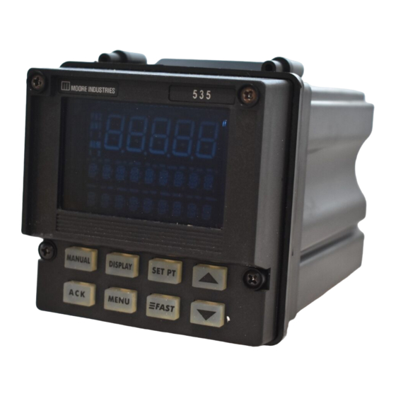
- Page 1 5 3 5 1/4 DIN PROCESS CONTROLLER USER'S MANUAL M535 V5, © MAY 2002...
-
Page 2: Table Of Contents
PAGE CHAPTER 1 About This Manual: INTRODUCTION ................1 Throughout this User’s Manual 535 Modes ..................1 information appears along the Order Code, Packaging Information ..........2 margins (NOTE:, CAUTION! and Where To Go Next ................2 WARNING!). Please heed these Text formatting in this manual ............ - Page 3 Pretune TYPE 2 or TYPE 3 and Adaptvie Tune ......91 Adaptive Tune by Itself ............. 92 Self Tune with Multiple Sets of PID ..........94 Self Tune with Time Proportioning Outputs ........ 94 Table of Contents 535 User's Manual...
- Page 4 Reset Menu Data ................A-11 Hardware Scan ................A-12 Slidewire Test ................A-12 Quick Calibration Procedure ............A-12 APPENDIX 5 SPECIFICATIONS ................ A-13 APPENDIX 6 GLOSSARY ................. A-17 APPENDIX 7 ISOLATION BLOCK DIAGRAM ........... A-23 535 User's Manual Table of Contents...
- Page 5 Figure 3.15 ..Position Proportioning Output Wiring ........18 Figure 3.16 ..Serial Communications Terminals ........19 Figure 3.17 ..535 Wiring with Limit Control ..........20 Figure 4.1 ..Location of Printed Circuit Boards for Hardware Configuration ..............21 Figure 4.2 ..
-
Page 6: Figure Description Page
Figure 7.20 ..Cascade Control of Product Temperature ......101 Figure 7.21 ..Ratio Control in Mixing Application ........103 Figure A4.1 ..535 Rear Terminals for Calibration ........7 Figure A4.2 ..Flowchart Calibration Menus ..........7 Figure A4.3 ..Jumper Locations on the Microcontroller Circuit Board ... 8 Figure A4.4 .. - Page 7 Table of Contents Table of Contents 535 User's Manual...
-
Page 8: Chapter 1 Introduction
The 535 is the most accurate instrument in its class. With a sampling rate of ten times per second, it is ideal for demanding pressure and flow applications. The 535 also offers a universal process input and modular, field interchange- able outputs that allow more flexibility than ever before. -
Page 9: 535 Modes
For important hardware installation guidelines, see Chapters 3 and 4. • For a detailed description of all the software menus and parameters of the 535, follow through Chapters 5 and 6. Appendix 1 can be used as a basic guideline to these parameters. TEXT FORMATTING IN THIS MANUAL... - Page 10 Certification Serial Communications Enter “0” if not desired RS-485 Serial Communications : Capability for position proportioning output is specifed by ordering 535-11xxAxxx00, 535-33xxAxxx00, or 535-44xxAxxx00. : Capability for Note 1 Note 2 velocity proportioning output is specifed by ordering 535-11xxxxxx00, 535-33xxxxxx00, or 535-44xxxxxx00.
- Page 11 Introduction Chapter 1 535 User’s Manual...
-
Page 12: Chapter 2 Basic Interface
MENU FAST Keys DISPLAYS The display strategy of the 535 Process Controller is the same for all control modes. 1st Display (five 7-segment digits) • For the process variable value. 2nd Display (nine 14-segment digits) • For the setpoint, deviation, output level or valve position (if available) •... -
Page 13: Keys
When lit, indicates the controller is in Set Up mode. FAST+MENU : Press to access the Set Up menus. FAST MENU In Set Up mode, press to advance through menus. (Use MENU by itself to access the parameters of a particular menu.) Chapter 2, Controller Operation 535 User's Manual... -
Page 14: Basic Operating Procedures
BASIC OPERATING PROCEDURES See the glossary in Appendix 6 for explanation of ramping and target Use the following as a quick guide to key operating functions of the 535. setpoint. Also refer to the applications To select /change a setpoint in Chapter 7. -
Page 15: Alarm Operation
Alarms may be used in systems to provide warnings of unsafe conditions. All mode. See Chapters 5 and 7 for details 535 operators must know how the alarms are configured, the consequences on alarms. of acknowledging an alarm and how to react to alarm conditions. - Page 16 This is similar to the function of a limit controller. More on Alarms For more details on how to set up alarms and for examples of various ways alarms can be set up, refer to the section on Alarms in Chapter 7. 535 User's Manual Chapter 2, Controller Operation...
- Page 17 Operation Chapter 2, Controller Operation 535 User's Manual...
-
Page 18: Installation
The 535 front face is NEMA 4X rated (waterproof). To obtain a waterproof seal between the controller and the panel, follow these directions: 1. The 535 fits in a standard 1/4 DIN cutout. Mount the 535 in any panel with a thickness from .06 in. to .275 in. (1.5 mm to 7.0 mm). -
Page 19: Wiring
AC power wiring at the extreme conditions. source distribution panel until all 1. For improved electrical noise immunity, install the 535 as far away as wiring connections are complete. possible from motors, relays and other similar noise generators. 2. Do not run low power (sensor input) lines in the same bundle as AC power lines. -
Page 20: Ac Power Input
Grouping these lines in the same bundle can create electrical noise interference. Screws must be tight to ensure good electrical connection Process Variable Input The 535 accommodates the following types of process variable inputs: • Thermocouple Input • RTD Input •... -
Page 21: Figure 3.6 ....... Pv1 And Pv2 Wiring For Milliamp, Rtd And Voltage Inputs
4-WIRE RTD Same color Same color Third leg of RTD Third leg Do NOT of RTD connect Same color 4th leg DO NOTconnect 4th leg VOLTAGE INPUT VOLTAGE INPUT – – – – Transmitter Transmitter Chapter 3 535 User's Manual... -
Page 22: Figure 3.7 ....... Pv1 And Pv2 Wiring For Milliamp Inputs With Internal And External Power Supply
– – 2-wire 2-wire transmitter the order code in Chapter 1 to transmitter determine if the 535 has a loop power module installed. To install a – – loop power module, refer to Chapter 4. MILLIAMP INPUT MILLIAMP INPUT... -
Page 23: Digital Input(S)
DIN 5 Screws must be tight to ensure electrical connection Remote Setpoint Option Use terminals 13 and 14 to connect the remote setpoint signal (see Figure 3.10). – Figure 3.10 – Source Remote Setpoint Terminals Chapter 3 535 User's Manual... -
Page 24: Output Modules
Install / Wire OUTPUT MODULES The 535 output modules are used for control, alarms and retransmission. The four output module types are: Mechanical Relay, Solid State Relay (Triac), DC Logic (SSR Drive) and Analog (Milliamp) To install these modules, plug them into any of the four output sockets on the printed circuit boards (refer to Chapter 4). -
Page 25: Dc Logic (Ssr Drive) Output
Milliamp Output Wiring Load 5. Position Proportioning Output (with or without Slidewire Feedback) POSITION PROPORTIONING OUTPUT Electric Motor Actuator Winding Winding Slidewire Wiper 0–1050 Ohm Figure 3.15 Actuator Position Proportioning Output Supply Wiring Current CCW COM Chapter 3 535 User's Manual... -
Page 26: Serial Communications
Comm + and Comm – Figure 3.16 Serial Communications Terminals Terminals To "Comm –" terminal of Comm – Twisted, shielded next Moore Industries device or other host RS-485 To "Comm +" terminal of port Comm + next Moore Industries device... -
Page 27: Limit Control
For such applications, we recommend the use of an FM-approved temperature limit device in conjunction with the process controller. This wiring example illustrates a typical application using the 535 Process Controller with a 353 Limit Figure 3.17 Controller. -
Page 28: Chapter 4 Hardware Set Up
NOTE: Thermocouple downscale and upscale burnout offers a choice The 535 accepts several different types of process variable signals. Set a jumper in which direction the controller location to specify the type of input signal. Set the signal range in the software would react in the event of thermocouple failure. -
Page 29: The Remote Setpoint
Female 22-Pin Connector Female 22-Pin Connector Remote Setpoint Jumper Male 22-Pin Male 22-Pin Connector Connector Output 4 Male 34-Pin Connector Female 34-Pin Connector 5-Pin Connector Module Retention Plate over Outputs 1,2,3 Jumpers NO and NC Chapter 4 535 User's Manual... -
Page 30: Accessing And Changing Jumpers
If it is difficult to slide the chassis in all the way, make sure the screws have been removed (they can block proper alignment), and that the chassis is properly oriented. 8. Carefully insert and align screws. Tighten them until the bezel is seated firmly against the gasket. Do not overtighten. 535 User's Manual Chapter 4... -
Page 31: Adding And Changing Output Modules
Hardware Set Up ADDING AND CHANGING OUTPUT MODULES The 535 has provisions for four output modules. A controller ordered with output module options already has the modules properly installed. Follow these in- structions to add modules, change module type(s) or change module location(s). - Page 32 13.Carefully insert and align screws. Tighten them until the bezel is seated firmly against the gasket. Do not overtighten. SPECIAL COMMUNICATIONS MODULE A special communications module is available for the 535; see order code in Chapter 1 for details. 535 User's Manual...
-
Page 33: Special Communications Module
If it is difficult to slide the chassis in all the way, make sure the screws have been removed (they can block proper alignment), and that the chassis is properly oriented. 6. Carefully insert and align screws. Tighten them until the bezel is seated firmly against the gasket. Do not overtighten. Chapter 4 535 User's Manual... -
Page 34: Software Configuration
CAUTION! All software changes occur in real time; In Set Up mode, there are 13 sets of options that control different aspects of 535 always perform set up functions under operation; in Tuning mode, there is one. Each set of options is called a menu. -
Page 35: Parameters
This manual displays these two types of param- eters differently; refer to Figure 5.2. A special feature of the 535, called Smart Menus, determines the correct parameters to display for the specific configu- ration, so not all the listed parameters will appear. -
Page 36: Configuration And Operation
For information about the installed options on the 535, compare the product label on top of the controller to the order code in Chapter 1. • To mount the controller and configure the wiring of the 535 for inputs and outputs, see Chapter 3. •... -
Page 37: Software Menus And Parameters
Output addressable through communication D OFF Completely deactivates the output Access Set Up Return to Operation Next menu Next parameter Next value Access Tuning Return to Operation DISPLAY MENU MENU FAST MENU FAST MENU DISPLAY Chapter 5 535 User's Manual... -
Page 38: Figure 3.4
4-20mA • 0–20 mA • 20–4 mA • 20–0 mA Access Set Up Return to Operation Next menu Next parameter Next value Access Tuning Return to Operation DISPLAY MENU MENU FAST MENU FAST MENU DISPLAY 535 User's Manual Chapter 5... -
Page 39: Figure 2.2
Status readable only through communications • PV2.SWITCH Switches between PV1 and PV2 Access Set Up Return to Operation Next menu Next parameter Next value Access Tuning Return to Operation DISPLAY MENU MENU FAST MENU FAST MENU DISPLAY Chapter 5 535 User's Manual... - Page 40 Status readable only through communications • PV2.SWITCH Switches between PV1 and PV2 Access Set Up Return to Operation Next menu Next parameter Next value Access Tuning Return to Operation DISPLAY MENU MENU FAST MENU FAST MENU DISPLAY 535 User's Manual Chapter 5...
-
Page 41: Pv1 Input
104° (the low limit of a type B thermocouple). • W5 T/C • PLAT.II T/C Access Set Up Return to Operation Next menu Next parameter Next value Access Tuning Return to Operation DISPLAY MENU MENU FAST MENU FAST MENU DISPLAY Chapter 5 535 User's Manual... - Page 42 Min. is SP LO. LIM. Maximum is HI RANGE D Dependent on HI RANGE Access Set Up Return to Operation Next menu Next parameter Next value Access Tuning Return to Operation DISPLAY MENU MENU FAST MENU FAST MENU DISPLAY 535 User's Manual Chapter 5...
-
Page 43: Pv2 Input
Enables user to enter different values for the following PV2 parameters Access Set Up Return to Operation Next menu Next parameter Next value Access Tuning Return to Operation DISPLAY MENU MENU FAST MENU FAST MENU DISPLAY Chapter 5 535 User's Manual... - Page 44 Setting for the low pass PV2 input filter. R 0 to 120 seconds D 0 seconds Access Set Up Return to Operation Next menu Next parameter Next value Access Tuning Return to Operation DISPLAY MENU MENU FAST MENU FAST MENU DISPLAY 535 User's Manual Chapter 5...
-
Page 45: Cust. Linr
Specifies the unit value corresponding to the XTH point (X is 2 to 14). XTH PV R –9999 to 99999 Access Set Up Return to Operation Next menu Next parameter Next value Access Tuning Return to Operation DISPLAY MENU MENU FAST MENU FAST MENU DISPLAY Chapter 5 535 User's Manual... -
Page 46: Control
Defines the lowest output value that can be achieved in automatic control. LOW OUT 0 – 100% Max is HIGH OUT Access Set Up Return to Operation Next menu Next parameter Next value Access Tuning Return to Operation DISPLAY MENU MENU FAST MENU FAST MENU DISPLAY 535 User's Manual Chapter 5... - Page 47 R 0 to S/W RANGE D Dependent on S/W RANGE value Access Set Up Return to Operation Next menu Next parameter Next value Access Tuning Return to Operation DISPLAY MENU MENU FAST MENU FAST MENU DISPLAY Chapter 5 535 User's Manual...
-
Page 48: Alarms
D PV • • RAMP SP • DEVIATION • OUTPUT • Access Set Up Return to Operation Next menu Next parameter Next value Access Tuning Return to Operation DISPLAY MENU MENU FAST MENU FAST MENU DISPLAY 535 User's Manual Chapter 5... - Page 49 Defines the latching sequence of alarm 1. NONE D LATCH • NO LATCH Access Set Up Return to Operation Next menu Next parameter Next value Access Tuning Return to Operation DISPLAY MENU MENU FAST MENU FAST MENU DISPLAY Chapter 5 535 User's Manual...
- Page 50 D PV • • RAMP SP • DEVIATION • OUTPUT • Access Set Up Return to Operation Next menu Next parameter Next value Access Tuning Return to Operation DISPLAY MENU MENU FAST MENU FAST MENU DISPLAY 535 User's Manual Chapter 5...
- Page 51 Defines the latching sequence of alarm 2. LATCHING:2 D LATCH LATCH • NO LATCH Access Set Up Return to Operation Next menu Next parameter Next value Access Tuning Return to Operation DISPLAY MENU MENU FAST MENU FAST MENU DISPLAY Chapter 5 535 User's Manual...
- Page 52 Defines the time period over which a rate-of-change alarm condition is determined. R 1 to 3600 seconds D 5 seconds Access Set Up Return to Operation Next menu Next parameter Next value Access Tuning Return to Operation DISPLAY MENU MENU FAST MENU FAST MENU DISPLAY 535 User's Manual Chapter 5...
-
Page 53: Rem. Setpt
R –9999 to 99999. Minimum value is BIAS LOW. D 1000 Access Set Up Return to Operation Next menu Next parameter Next value Access Tuning Return to Operation DISPLAY MENU MENU FAST MENU FAST MENU DISPLAY Chapter 5 535 User's Manual... -
Page 54: Retrans
R –9999 to 99999 D Dependent on the process variable range Access Set Up Return to Operation Next menu Next parameter Next value Access Tuning Return to Operation DISPLAY MENU MENU FAST MENU FAST MENU DISPLAY 535 User's Manual Chapter 5... -
Page 55: Self Tune
D AUTOMATIC (Controller defines this point, low end for Automatic) Access Set Up Return to Operation Next menu Next parameter Next value Access Tuning Return to Operation DISPLAY MENU MENU FAST MENU FAST MENU DISPLAY Chapter 5 535 User's Manual... - Page 56 (used by POWERBACK algorithm). R 0.1 seconds to 7200.0 seconds D 0.1 seconds Access Set Up Return to Operation Next menu Next parameter Next value Access Tuning Return to Operation DISPLAY MENU MENU FAST MENU FAST MENU DISPLAY 535 User's Manual Chapter 5...
-
Page 57: Special
Controller Set Up SPECIAL SPECIAL 1. AUTO. TRIP Defines the condition under which the 535 will automatically trip to automatic AUTO. TRIP control from manual control upon start up. D OFF Deactivates this function • RISING PV Will trip when a rising process variable is within the specified deviation from the setpoint •... -
Page 58: Security
Defines lockout status of the tuning parameters. UNLOCKED D UNLOCKED • LOCKED Access Set Up Return to Operation Next menu Next parameter Next value Access Tuning Return to Operation DISPLAY MENU MENU FAST MENU FAST MENU DISPLAY 535 User's Manual Chapter 5... -
Page 59: Ser. Comm
• D LAST OUT D OFF • D OUTS. OFF Access Set Up Return to Operation Next menu Next parameter Next value Access Tuning Return to Operation DISPLAY MENU MENU FAST MENU FAST MENU DISPLAY Chapter 5 535 User's Manual... - Page 60 R Any value in the process variable range D Dependent on the process variable range Access Set Up Return to Operation Next menu Next parameter Next value Access Tuning Return to Operation DISPLAY MENU MENU FAST MENU FAST MENU DISPLAY 535 User's Manual Chapter 5...
- Page 61 14 CONTACT 3 Operation of the third digital input 15 CONTACT 4 Operation of the fourth digital input 16 CONTACT 5 Operation of the fifth digital input 17 LOOP NAME Nine character message associated with control loop Chapter 5 535 User's Manual...
- Page 62 7 FILTER Setting for the low pass PV2 input filter (in seconds) 8 OFFSET Offset to the PV2 in engineering units 9 GAIN Gain to PV2 10 RESTORE Control mode when a broken PV2 is restored 535 User's Manual Chapter 5...
- Page 63 Nine character message associated with alarm 2 21 FAULT Alarm relay status if fault condition is detected 22 OUTPUT Output if the rate-of-change alarm is tripped 23 RATE TIME Time period over which a rate-of-change alarm is determined Chapter 5 535 User's Manual...
- Page 64 Input signal for the 14th point (of the 15 point curve) 30 14th PV Engineering unit value for the 14th point 31 15th INPUT Input signal for the15th point (of the 15 point curve) 32 15th PV Engineering unit value for the 15th point 535 User's Manual Chapter 5...
- Page 65 14 CLOSE F/B Feedback ohm value when the valve is closed 15 OUT1 STOP Stopping point for control output 1 when staging outputs 16 OUT2 STRT Starting point for control output 2 when staging outputs Chapter 5 535 User's Manual...
- Page 66 Nine character message associated with alarm 2 19 FAULT Alarm status if a fault condition is detected 20 OUTPUT Output if the rate-of-change alarm is tripped 21 RATE TIME Time period over which a rate-of-change will be determined 535 User's Manual Chapter 5...
- Page 67 What is to be retransmitted for retransmission output 4 8 LOW RANGE:4 Low end of range in eng. units for retransmission output 4 9 HI RANGE:4 High end of range in eng. units for retransmission output 4 Chapter 5 535 User's Manual...
- Page 68 5 PWR. UP:OUT. Output of the controller is powering up in manual control 6 PWR. UP: SP Setpoint upon power up 7 NO. OF SP #of setpoints stored for selection by digital input or SET PT key 535 User's Manual Chapter 5...
- Page 69 State of the controller if communications is lost (sheds) 6 SHED OUT. Output if the unit sheds 7 SHED SP Setpoint status if communications is lost 8 DESIG. SP Value of the setpoint if controller sheds Chapter 5 535 User's Manual...
-
Page 70: Chapter 6 Tuning
TUNING OVERVIEW NOTE: The self tuning function of the 535 consists of two distinct components — For more information about Pretune Pretune and Adaptive Tune. In addition, you may choose from three types and Adaptive Tune, refer to the section of Pretune: on Tuning applications in Chapter 7. -
Page 71: Tuning Menu Parameters
15.0 R 0.3 to 120.0 seconds D 15.0 seconds Access Set Up Return to Operation Next menu Next parameter Next value Access Tuning Return to Operation DISPLAY MENU MENU FAST MENU FAST MENU DISPLAY Chapter 6 535 User's Manual... - Page 72 15.0 output. R 0.3 to 120.0 seconds. D 15.0 seconds Access Set Up Return to Operation Next menu Next parameter Next value Access Tuning Return to Operation DISPLAY MENU MENU FAST MENU FAST MENU DISPLAY 535 User's Manual Chapter 6...
- Page 73 PID parameter in the third display with an “ * ” on either side. Access Set Up Return to Operation Next menu Next parameter Next value Access Tuning Return to Operation DISPLAY MENU MENU FAST MENU FAST MENU DISPLAY Chapter 6 535 User's Manual...
- Page 74 R The process variable range D Dependent on the process variable range Access Set Up Return to Operation Next menu Next parameter Next value Access Tuning Return to Operation DISPLAY MENU MENU FAST MENU FAST MENU DISPLAY 535 User's Manual Chapter 6...
-
Page 75: Tuning Parameter Value Chart
Defines the proportional band for PID set 3. 27. RESET:3 Defines the integral time for PID set 3. 28. RATE:3 Defines the derivative time for PID set 3. 29. MAN. RST.:3 Defines the manual reset (or load line) for PID set 3. Chapter 6 535 User's Manual... - Page 76 Defines the derivative time for PID set 8. 54. MAN. RST.:8 Defines the manual reset (or load line) for PID set 8. 55. TRIP:8 This defines the value that triggers a change to the 8th PID set. 535 User's Manual Chapter 6...
-
Page 77: Self Tune Messages And Troubleshooting
Tuning SELF TUNE MESSAGES AND TROUBLESHOOTING Refer to Chapter 7 for more information on the Self Tune function of the 535 controller. When the Pretune function terminates, one of the following messages will appear: Message Pretune Conclusion/Problem Corrective Action Type... -
Page 78: Applications
P. Load Line ..........97 A. CONTROL TYPE Software Configuration 1. Go to the CONTROL menu. 2. For the parameter ALGORITHM, select the type of 535 control: • ON-OFF “Crude” control similar to a household thermostat. Used primarily on slow, stable processes where moderate deviation (cycling) around setpoint is tolerable. -
Page 79: Alarms
For derivative action based on process variable changes, choose PV. B. ALARMS The 535 controller has two extremely flexible and powerful software alarms. The number of available outputs limits how alarms are linked to relays. A Global Alarm feature allows all alarms to be assigned to the same relay. - Page 80 MANUAL Alarm occurs when the controller is put into manual mode of opera- tion. This may be useful for security purposes or to alert the operator that 535 is no longer under automatic control. • RATE Alarm occurs when the process variable changes at a rate greater than what is specified by the alarm setpoint and time base.
- Page 81 10 units per second. B. If the alarm setpoint is set to 100 and the time base set to 10, the rate of change is also 10 units per second. Chapter 7 535 User's Manual...
-
Page 82: Figure 7.1 ....... Alarm Examples
ALM.:1 OUT. = N (N = 2 to 4) ALM.:1 OUT. = N (N = 2 to 4) LATCHING = LATCH LATCHING:1 = LATCH ACK.:1 = ENABLED ACK.:1 = DISABLED ALARM SP:1 = (<0) POWER UP:1 = ALARM 535 User's Manual Chapter 7... -
Page 83: Duplex Control
When using PID control, the 535 controller actually displays the PID output. To relate this output to the actual physical output, locate the PID output on the... -
Page 84: Duplex With Reverse And Direct Acting Outputs
PID OFST.:1 = 0 100% 100% PID OFST.:2 = 0 LOW OUT = 0 Figure 7.3 HIGH OUT = 100 Duplex with Direct and Reverse REL. GAIN = 1.0 Out 1 Acting Outputs Out 2 100% PID OUTPUT 535 User's Manual Chapter 7... -
Page 85: Duplex With 2 Reverse Acting Outputs
PID OFST.:2 = – VALUE 100% 100% LOW OUT = 0 Figure 7.5 HIGH OUT = 100 Duplex with a Gap Between Outputs REL. GAIN = 1.0 Out 1 Out 2 100% Offset 1 Offset 2 PID OUTPUT Chapter 7 535 User's Manual... -
Page 86: Duplex With Overlapping Outputs And Output Limits
LOW OUT = 0 Out 2 HIGH OUT = 100 Out 1 REL. GAIN = 2.0 REL. GAIN = 1.0 REL. GAIN = 0.5 Figure 7.7 Duplex with Various Relative Gain Settings 100% PID OUTPUT 535 User's Manual Chapter 7... -
Page 87: Duplex With One On/Off Output
ACTION:2 = DIRECT (Heat) (Cool) ON OFST.:1 = – VALUE Figure 7.9 ON OFST.:2 = + VALUE Duplex with Two ON/OFF Outputs Out 1 Out 2 Offset 1 Offset 2 High Range Range PROCESS VARIABLE Chapter 7 535 User's Manual... -
Page 88: Slidewire Position Proportioning Control
Place controller under Manual control. d. Change the output percentage and observe if the valve stabilizes at NOTE: P.PROP.D.B. can only be configured if the Slidewire Feedback is the new value. wired to the controller. 535 User's Manual Chapter 7... -
Page 89: Velocity Position Proportioning Control
5. Set MIN. TIME to the minimum amount of time the controller must specify for the motor to be on before it takes any action. 6. Set values for PV. BREAK, DES. OUTPT., PWR.UP:OUT. and SHED OUT. Chapter 7 535 User's Manual... -
Page 90: Staged Outputs
RETRANS. 3. Go to the RETRANS. menu. 4. Set the corresponding parameter, TYPE:X, for the first retransmission out- put to define what is being transmitted: the process variable, setpoint, ramp- ing setpoint or output. 535 User's Manual Chapter 7... -
Page 91: Digital Inputs
0=open contact • REM. SETPT. Closing input changes active setpoint to remote setpoint. Opening reverts controller to previous setpoint. Override by selecting a dif- ferent setpoint via the SET PT key, a communications command, or Chapter 7 535 User's Manual... - Page 92 Closing contact mimics the FAST key . Use in conjunction with , DISPLAY and MENU keys. • MENU KEY Closing contact mimics the MENU key. In OPERATION Mode, pro- vides entry to TUNING menu. In SET UP or TUNING Mode, ad- 535 User's Manual Chapter 7...
-
Page 93: Remote Setpoint
• PV2.SWITCH (only applicable for PV SOURCE = 1/2:SWITCH). Closing contact causes the 535 to use PV2 as the PV input (instead of PV1). Basic Operating Procedures NOTE: There is a one-second delay before a closed digital input takes 1. -
Page 94: Multiple Setpoints
K. MULTIPLE SETS OF PID VALUES The 535 has the ability to store up to eight sets of PID values. This can be a valuable feature for operating the controller under conditions which require different tuning parameters for optimal control. There are various methods of selecting which set should be active. -
Page 95: Powerback
Using with Adaptive and Pretune The 535 can be programmed to automatically set the PID values using the Pretune and Adaptive Tuning functions. For both functions, the tuned set of PID is that which is active upon initiation of the tuning function. -
Page 96: Self Tune-Powers Powertune
Applications M. SELF TUNE—POWERTUNE® The Self Tune function of the 535 consists of two distinct components, Pretune and Adaptive Tune. These components may be used independently or in conjunction with one another. For best results, we recommend using them together. - Page 97 • B to C is an impulse to determine initial PID values and response Out Step time. • C is Pretune completed, so Adaptive PID control begins if ENABLED. CONTROL OUTPUT NOISE BUMP ADAPTIVE TIME Pretune Chapter 7 535 User's Manual...
-
Page 98: Pretune Type 1 And Adaptive Tune
Pretune if set to do so, or upon manual transfer. Figure 7.12 illustrates the operation of Pretune TYPE 1 with Adaptive Tune. Pretune TYPE 2 or 3 & Adaptive Tune 1. Go to the SELF TUNE menu. 2. Set the TYPE parameter to BOTH. 535 User's Manual Chapter 7... -
Page 99: Adaptive Tune By Itself
(i.e., load changes), but it cannot compensate (407 – 402) NOISE BAND = X 100 = PROCESS [ 752 – (–352) ] VARIABLE Type T Thermocouple Figure 7.13 Noise Band Calculation Example Range –328°F TO 752° F –328 (SECONDS) TIME Chapter 7 535 User's Manual... -
Page 100: Figure 7.13
63% of its new (expected) value, the response time is 300 seconds. Figure 7.15 If the response time is set too short, the process will be unstable and cycle Deadtime and Time Constant 535 User's Manual Chapter 7... -
Page 101: Self Tune With Multiple Sets Of Pid
Note that when output limits are used, the full output range from -5 to 105% is available in manual control. N. RAMP-TO-SETPOINT The 535 contains a ramp-to-setpoint function that may be used at the user’s discretion. This function is especially useful in processes where the rate-of- change of the setpoint must be limited. -
Page 102: Input Linearization
The ramp-to-setpoint function is triggered by one of three conditions: 1. Upon power up, if the 535 powers up in automatic control, then the setpoint will ramp from the process variable value to the setpoint value at the specified rate. -
Page 103: Custom Linearization
Applications the signal must be calculated. The 535 has the capability to perform this square root linearization. For the first 1% of the input span, the input is treated in a linear fashion. Then it is a calculated value, using the formula in Figure 7.16. -
Page 104: Load Line
“cold” start. Q. SECURITY The 535 security system is easily customized to fit a system’s needs. Software Configuration NOTE: SEC CODE does not appear unless all functions are unlocked. -
Page 105: Reset Inhibition
3” to compensate. 3. Set PV GAIN. This multiplies the deviation from the low end of the process variable range by the gain factor and then adds it to the value of the low end Chapter 7 535 User's Manual... -
Page 106: Serial Communications
Software Configuration 1. Access the SER. COMM. menu. 2. STATION specifies the unit’s station address. It is the only way one 535 can be distinguished from another. Each 535 on the same RS-485 interface must have a unique station address. -
Page 107: Cascade Control
Example In Figure 7.19 we have a 535 set up to control a heat exchanger. In a PID- equipped heat exchanger, pressure in the steam shell more quickly reflects fluctuations in the steam supply than does the process liquid’s temperature. -
Page 108: Figure 4.3
This delay in the transfer of heat prevents the 535 controller from controlling the temperature more precisely. The solution to the problem is illustrated in Figure 7.20. Have the PID controller position the steam valve, but add a sensor by means of another 535 controller OUT 1– OUT 1–... - Page 109 Pretune on this loop. Once this Pretune is complete, the Cas- cade Control Loop is completely tuned. Place Unit #1 into Automatic con- trol to allow the system to control to the desired Setpoint of the Primary loop. Chapter 7 535 User's Manual...
-
Page 110: Ratio Control
Material B is measured at 50 gallons/minute, the effective remote setpoint value would be 2 times 50, or 100. The 535 controller would try to maintain the flow of Material A at 100. As the flow of Material B changes, the setpoint would change accordingly, always in a 2:1 ratio. - Page 111 2. Adjust the ratio between the two streams: a. Go to the TUNING menu. b. Set the RSP RATIO parameter. The value of this parameter will be multiplied by the remote setpoint signal to yield the effective remote setpoint. Chapter 7 535 User's Manual...
-
Page 112: Appendix 1
POWER UP PWR. UP:OUT. PWR. UP:SP NO. OF SP SECURITY SEC. CODE SP ADJUST AUTO./MAN. SP SELECT ALARM ACK. TUNING CONFIGURE SHED OUT. SER. COMM. STATION BAUD RATE SHED TIME SHED MODE SHED SP DESIG. SP 535 User's Manual Appendix 1... - Page 113 PROP. BND.:4 RESET:4 RATE:4 MAN. RST.:4 TRIP:4 PROP. BND.:5 RESET:5 RATE:5 MAN. RST.:5 TRIP:5 PROP. BND.:6 RATE:6 MAN. RST.:6 RESET:6 TRIP:6 PROP. BND.:7 RATE:7 MAN. RST.:2 RESET:7 TRIP:7 PROP. BND.:8 RATE:8 MAN. RST.:8 RESET:8 TRIP:8 Appendix 1 535 User's Manual...
-
Page 114: Appendix 2
Module Retention Kit for Outputs 1-3 ( Includes Retention Plate) 535 664 Module Retention Kit for Output 4: Set of 5 Tie Wraps 535 665 Circuit Board Support (Bezel Insert) 535 075 Engineering unit labels (1 sheet) 535 106 535 User's Manual Appendix 2... - Page 115 Parts List Appendix 2 535 User's Manual...
-
Page 116: Appendix 3
Can’t switch to auto control Input sensor signal is not connected or valid See PV LOST message Erratic display Resetting action due to electrical noise on Filter power line. powerline PID values not set properly Retune controller 535 User's Manual Appendix 3... - Page 117 EEPROM change. Call factory for assistance. numbers. Controller locks up until fixed. During cold junction calibration, a discrepancy Install the 535 chassis into the actual case with which CAL.ERROR was found between the controller type and the it was shipped, then run calibration again. If you SEE.MANUAL...
-
Page 118: Appendix 4
Failure to do so may result in small junction tem- Figure A4.1 perature (0.6°C/1.1°F). 535 Rear Terminals for Calibration Access the parts of the calibration menu as shown in Figure A4.2. Figure A4.2 CAL. VREF... -
Page 119: Preparation For All Input Calibrations
(and FAST) keys on the controller until the display on the ELECTRIC SHOCK HAZARD! Terminals 1 and 2 carry live power. DO controller matches the meter reading. NOT touch these terminals when power is on. Appendix 4 535 User's Manual... -
Page 120: Thermocouple Cold Junction Calibration
3. Press MENU until the display indicates CALIBRATE ANA. mA IN, then press ACK. If the display shows PV1=20mA PRESS ACK, move ahead to step #8. 4. The controller will display SET BOTH JUMPER=mA. 5. Power down the controller and remove chassis from the case. 535 User's Manual Appendix 4... -
Page 121: Milliamp Output Calibration
• Two small pieces of wire for every milliamp output • Test leads with banana clips • #2 Phillips screwdriver 1. Disconnect power to the instrument. 2. Remove chassis from case. A-10 Appendix 4 535 User's Manual... -
Page 122: Reset Menu Data
If successful, RESET COMPLETED will appear in the display. If failed, RESET SKIPPED will appear instead. 7. To try again, press ACK key, and then press MENU key within two seconds. 8. When complete, return jumpers to their original positions. A-11 535 User's Manual Appendix 4... -
Page 123: Hardware Scan
If the value is not correct, use the keys to scroll to the correct value. 11. Repeat steps 4 through 10 to verify all values. 12. Press DISPLAY to return to the Operation mode. A-12 Appendix 4 535 User's Manual... -
Page 124: Appendix 5
CONTROLLER ARCHITECTURE Display accuracy is ± 1 digit. These accuracy specifications are at The 535 Controller hardware can be configured as follows: reference conditions (25°C) and only apply for NIST ranges. Inputs: One universal process variable input is standard. Available Detailed accuracy information is available upon request. - Page 125 (–5 to 105%). Thermocouple burnout is selectable for upscale or ALARMS downscale. The 535 controller has two software alarms. High and low alarms may be sourced to the PV, SP, RAMP SP, DEVIATION INPUT FILTER and OUTPUT. If an alarm is tripped, the alarm message will...
- Page 126 MAN key illuminated: controller is in manual control mode. ACK key illuminated: alarm may be acknowledged. SET PT key illuminated: setpoint other than primary local setpoint is active. (Continued on following page) MENU key illuminated: controller is in configuration mode. A-15 535 User's Manual Appendix 5...
- Page 127 Specifications A-16 Appendix 5 535 User's Manual...
-
Page 128: Glossary
In hardware, a set of adaptive tune: A component of the variable (PV) value. conductors that can be brought into 535 self tune function which contact by electromechanical action baud rate: Any of the standard continuously monitors the process and thereby produce switching. - Page 129 A terminal used on where the operator determines the derivative: Anticipatory action that the 535 to ensure, by means of a control output. senses the rate of change of special connection, the grounding temperature, and compensates to (earthing) of part of the controller.
- Page 130 An unwanted component of a linearization, square root: A signal or variable. input: Process variable information function the 535 uses to linearize a being supplied to the instrument. non-linear signal corresponding to noise band: A measurement of the the flow being measured by flow amount of random process “noise”...
- Page 131 (on/off) pretune algorithm: A method by automatically eliminates offset, or such as a relay, or analog which the 535 controller initiates an “droop,” between setpoint and actual (continuously variable) for current output value change, monitors the process temperature.
- Page 132 A function that defines whether the local setpoint will track station address: The unique the remote setpoint. When the identifier assigned to a device for controller is transferred to a local communications. A-21 535 User's Manual Appendix 6...
- Page 133 Glossary A-22 Appendix 6 535 User's Manual...
-
Page 134: Appendix 7
1 minute. 3. Milliamp, Loop Power and SSR Drive modules in output positions 1, 2, and 4 are not isolated from each other. SSR Driver Milliamp Module Mechanical Relay Loop Power SSR Output A-23 535 User's Manual Appendix 7... - Page 135 Isolation Block Diagram A-24 Appendix 7 535 User's Manual...
- Page 136 4. Ship the equipment to the Moore Industries location nearest you. The returned equipment will be inspected and tested at the factory. A Moore Industries representative will contact the person designated on your documentation if more information is needed. The repaired equipment, or its replacement, will be returned to you in accordance with the shipping instructions furnished in your documentation.
- Page 137 Installation 500 SERIES Form M500 V6 Process Controllers 5 0 0 Hardware Installation and Modification Manual for Electronic Products Series 531, 532, 535, 545, 555 Model 2 Installation Guide 500 Series M500 V6, JUNE 2005...
- Page 138 Installation INTRODUCTION This technical brochure provides hardware installation and modification instructions for our controllers: Series 531, 532, 535, 545, and 555. Use these instructions with the following kits: Display Assembly Kits EPROM Kits 531-632 ....531 Display Assembly Kit 531-740 ....531 EPROM Kit 532-632 ....
-
Page 139: Configuration
Installation INSTRUCTIONS one of the larger two boards from the Option Board (Photo 4). Be careful not to bend the connector pins. Separate the other board in the To Disassemble the Unit same manner. For any hardware modifications, disassemble the unit. Figure 2 (opposite page) shows the Microcontroller 1. - Page 140 Installation NOTE: Front of Unit Back of Unit If you replace the EPROM chip, you must align the notch facing the front (toward Operator Interface) (toward rear terminals) of the unit. EPROM BATTERY 5-Pin Connector Female 22-Pin Connector Female 22-Pin Connector NOTE: The 5- and 22-Pin connnectors on the boards are all keyed so they...
- Page 141 Static discharge will cause damage to equip- ment. Always ground yourself with a wrist 20. To maintain NEMA 4X Rating, you may need new grounding strap when handling electronics mounting gaskets, order part #535-662. Refer to to prevent static discharge. your user’s manual. CAUTION Do not scratch the boards or bend the pins of the connectors.
- Page 142 Conforms to the following safety standard: EN 61010-1, 2001 Supplemental Information: CE option requires CE KIT PN 535-766. Janurary 9, 2003 ______________________________ _____________________________________ Date Fred Adt Robert Stockham Quality Assurance Director Moore Industries-International, Inc. European Contact: Your Local Moore Industries Sales and Service Office...
- Page 143 Conforms to the following safety standard: EN 61010-1, 2001 Supplemental Information: CE option requires CE KIT PN 535-765. August 15, 2005 ______________________________ _____________________________________ Date Fred Adt Robert Stockham Quality Assurance Director Moore Industries-International, Inc. European Contact: Your Local Moore Industries Sales and Service Office...
- Page 144 4. Ship the equipment to the Moore Industries location nearest you. The returned equipment will be inspected and tested at the factory. A Moore Industries representative will contact the person designated on your documentation if more information is needed. The repaired equipment, or its replacement, will be returned to you in accordance with the shipping instructions furnished in your documentation.
Need help?
Do you have a question about the 535 and is the answer not in the manual?
Questions and answers