Table of Contents
Advertisement
Quick Links
Advertisement
Table of Contents

Subscribe to Our Youtube Channel
Related Manuals for Crossfire X400


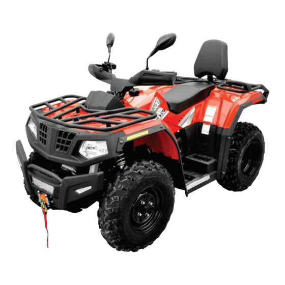
Summary of Contents for Crossfire X400
- Page 1 X400 ATV USER MANUAL...
- Page 2 Owner's Manual...
- Page 3 Owner's Manual INTRODUCTION Congratulations on your purchase of the HS400ATV-8. This Owner’s / Operator’s manual will provide you information regarding safe operation, operational instructions , maintenance and care. Fully understanding this manual and following all of the instructions herein will provide the knowledge needed to have a safe and enjoyable ATV operation.
- Page 4 Owner's Manual IMPORTANT MANUAL INFORMATION FAILURE TO FOLLOW THE WARNINGS CONTAINED IN THIS MANUAL CAN RESULT IN SERIOUS Particularly important information is distinguished in this manual using the INJURY OR DEATH. following notations: The Safety Alert Symbol means ATTENTION! YOUR SAFETY IS INVOLVED! Failure to follow WARNING instructions could result in severe injury or death to the machine operator, a bystander or a person inspecting or repairing the machine.
- Page 5 Owner's Manual IMPORTANT NOTICE The turning speed of this ATV should not exceed 25km/h. This ATV is designed and manufactured OFF-ROAD use only. It is illegal and unsafe to operate this ATV on any public street, road or highway. This ATV complies with all applicable OFF-ROAD noise level and spark arrester laws and regulations in effect at the time of manufacture.
-
Page 6: Table Of Contents
Owner's Manual Location of the Warning and brakes 4-14 Specification Labels Parking brake – Park position lever 4-15 Safety Information Gear shift lever 4-16 Fuel Tank Cap 4-16 Description and Vehicle Seat 4-17 Identification Front & Rear Carrier 4-17 Vehicle Identification Number DC Socket 4-20 EC signs... - Page 7 Owner's Manual Tires 5-10 Your Vehicle How to Measure Tire Pressure 5-11 Driving Your Vehicle Tire Wear Limit 5-12 Ride with care and good Judgment Apparel Operation Speed Limiter Starting a cold engine Loading and Accessories Starting a Warm Engine During Operation Warming the engine Modifications...
- Page 8 Owner's Manual Periodic Maintenance Chart for Adjusting the Brake Pedal 8-31 the Emission Control System Inspecting / Lubricating Cables 8-32 General Maintenance and Lubricating the Brake Lever and Lubrication Chart Brake Pedal 8-32 EFI System Rear Knuckle Upper and Lower Engine Oil and Oil Filter Pivot Lubrication 8-33...
- Page 9 Owner's Manual Fault codes for the Electronic Fuel Injection System 11-1 USA EPA Emissions Limited Warranty 12-1...
- Page 10 Location of the Warning and Safety Labels LOCATION OF THE WARNING AND SPECIFICATION LABELS...
- Page 11 Location of the Warning and Safety Labels Read and understand all of the labels on your machine. They contain important information for safe and proper operation of your ATV. Never remove any labels from your ATV. If a label becomes difficult to read or comes off, a replacement label is available from your dealer.
- Page 12 Location of the Warning and Safety Labels...
- Page 13 Location of the Warning and Safety Labels...
- Page 14 Location of the Warning and Safety Labels...
-
Page 15: Safety Information
Safety Information SAFETY INFORMATION This ATV is a special vehicle, which is different from other vehicles such as motorcycles and cars. A collision or rollover can occur quickly, even during routine maneuvers such as turning and riding on hills or over obstacles if you fail to take proper precautions. SEVERE INJURY OR DEATH can result if you do not follow these instructions: Read this manual and all labels carefully and follow the operating procedures described. - Page 16 Safety Information shirt or jacket, and long pants. Never use alcohol or drugs before or while operating an ATV. Never operate it at a high speed for your skills. Always operate it at a speed that is proper for the terrain, visibility and operating conditions, and your experience.
- Page 17 Safety Information Always follow proper procedures for climbing hills as described in this manual. Check the terrain carefully before climbing any hill. Never climb those hills with excessively slippery or loose terrain. Keeping your weight forward, never open the throttle suddenly. Never go over the top of a hill at a high speed.
- Page 18 Safety Information Always be careful when skidding or sliding. Learn to control the vehicle in skidding or sliding by practicing at low speeds and on level, smooth terrain. On extremely slippery surfaces, go slowly and be very cautious in order to reduce the chance of out of control. NEVER ride your ATV on an icy road.
- Page 19 Safety Information WARNING If you swallow gasoline or inhale gasoline fumes, or get gasoline in your eyes, see your Improper handling of gasoline may cause fire doctor immediately. If gasoline spills on your and you could be burned. Remember: Always turn off the engine when skin, wash with soap and water.
- Page 20 Safety Information WARNING POTENTIAL HAZARD Starting or running the engine in a closed area. WHAT CAN HAPPEN Exhaust fumes are poisonous and may cause loss of consciousness and death within a short time. HOW TO AVOID THE HAZARD Always operate your ATV in an area with good ventilation.
- Page 21 Description and Vehicle Identification DESCRIPTION AND MACHINE IDENTIFICATION...
- Page 22 Description and Vehicle Identification...
-
Page 23: Vehicle Identification Number
Description and Vehicle Identification NOTE: 2. VEHICLE IDENTIFICATION NUMBER: The ATV you have purchased may differ slightly from those shown in the figures of this manual. 3. MODEL LABEL INFORMATION: ○ ● Identification number records Record the vehicle identification number, Vehicle identification number engine identification number and model vehicle... -
Page 24: Model Label
Description and Vehicle Identification [1]. Engine identification number NOTE: [1]. Vehicle identification number The engine identification number also is NOTE: used to identify your machine. The vehicle identification number is used to identify your machine. Model label The model label is affixed at the location Engine identification number shown in the illustration. - Page 25 Description and Vehicle Identification information on this label in the space provided. This information will be needed to order replacement parts from your dealer. [1]. Model label...
-
Page 26: Control Functions
Control Functions CONTROL FUNCTIONS The engine can be started only in this position Ignition switch and the headlights and taillights can be turned Switch functions in respective positions are as on when the light switch is on. follows: OFF: All electrical circuits are switched off. The key can be removed in this position. -
Page 27: Indicator And Warning Lights
Control Functions Indicator and Warning Lights Neutral indicator“N” This indicator comes on when the drive select lever is in the “N” position. Reverse indicator“R” This indicator comes on when the drive select lever is in the “R”position. Park indicator “P” 1. -
Page 28: Speedometer Unit
Control Functions Speedometer Unit CAUTION: The engine may overheat if the ATV is overloaded. If this happens, reduce the load to specification. Headlight indicator “ ” When the headlights are on, this indicator will light. 1. RPM indicator 2. Odometer/trip meter/Eng. hours & Clock adjustment Position light indicator“... - Page 29 Control Functions an odometer (which shows the total The odometer displays the total distance distance covered) traveled by the ATV. The trip meter can a trip meter (which can be cleared and record distances up to 999.9 miles for specific then show any new distances traveled) trips.
- Page 30 Control Functions 1. Press the right button to set the hour. speeds to accommodate turning. 2. Press the left button again and the clock Differential gear lock indicator “DIFF-LOCK” goes into the minute ‘set’ mode. The right 4WD symbol will show an ‘X’ over 3.
-
Page 31: Fault Code Indicator
Control Functions the stability and safety of the ATV operation. Fault code indicator CAUTION: When the EFI encounters faults, the ECU will When the selector is set to 4WD “DIFF. send the fault code to the instrument display, LOCK”, the right 4WD symbol front axle will and it will flash on the clock. -
Page 32: Left Handlebar Switches
Control Functions Left handlebar switches 1. Light switch “ / OFF / ” 2. Starter button “ ” [1]. Fuel level indicator in lower position [2]. Fuel level indicator in higher position 3. Turning signal switch 4. Engine stop button “ ”... - Page 33 Control Functions Toggle switch “ ” to turn on the high NOTE: beams. See starting instructions prior to starting the Toggle switch “OFF” to turn off all the lights. engine. (See P6-1—6-2) Toggle switch “ ” to turn on the parking lights and the taillights.
- Page 34 Control Functions Horn button This ATV is equipped with a“4WD/LOCK” Press this button, horn activates. switch to lock the differential according to terrains and conditions. Emergency flasher button “2WD/4WD”switch Press this button, the four turn signal lights will flash continuously with a buzzer sound. 2WD/4WD operation This ATV is equipped with two-wheel and four wheel drive switch "2WD/4WD".
- Page 35 4-10 Control Functions “4WD/ LOCK”switch Four–wheel drive with the differential gear locked (“4WD-LOCK”): Power is supplied to the rear and front wheels when the differential gear is locked. Unlike the 4WD mode, all wheels turn at the same speed regardless of traction.
- Page 36 Control Functions 4-11 2WD/4WD selection From 4WD to 2WD To change from 4WD to 2WD .stop the vehicle ,be sure the select lever is set to position and then set the switch to “2WD”. Switch “4WD”/”LOCK” To lock the differential gear in 4WD, stop the vehicle, make sure the On-Command Selection lever switch four-wheel-drive switch is set to “4WD”, move...
-
Page 37: Throttle Lever
4-12 Control Functions and forth will help the differential gear lock WARNING to engage. POTENTIAL HAZARD Riding before the differential gear lock When driving too fast with DIFF.LOCK on. is properly engaged (e.g., when the WHAT CAN HAPPEN indicator and indicator light are Four wheels will rotate at the same speed. - Page 38 Control Functions 4-13 WARNING POTENTIAL HAZARD Malfunction of the throttle. WHAT CAN HAPPEN The throttle could be hard to operate, making the ATV difficult to speed up or slow down when needed, which could cause an accident. HOW TO AVOID THE HAZARD 1.
-
Page 39: Speed Limiter
4-14 Control Functions Speed limiter WARNING The speed limiter keeps the throttle from fully opening even when the throttle lever is POTENTIAL HAZARD pushed to the maximum. Turn the adjusting Improper adjustment of the speed limiter WHAT CAN HAPPEN screw to limit the maximum engine power The throttle cable could get damaged. -
Page 40: Lever
Control Functions 4-15 down the pedal will stop the ATV. This brake maintain the ATV brake in the on position, pedal controls the entire brake system. It which will also activate the park position applies brakes to all the wheels. indicator on the display. -
Page 41: Gear Shift Lever
4-16 Control Functions Gear shift lever Fuel tank cap The gear shift lever is used to shift your ATV The fuel tank cap is located on the middle into the forward(F),neutral (N) and the reverse side of the ATV. Remove the fuel tank cap by (R) positions. -
Page 42: Seat
Control Functions 4-17 Make sure that the seat fits securely. SEAT 1. To remove the seat, pull the seat lock lever Front & Rear Carrier upward and pull up the seat at the rear. Maximum load limit of front carrier: 20kg Maximum load limit of rear carrier: 35kg [1]. - Page 43 4-18 Control Functions Front/rear shock absorber adjustment The spring preload can be adjusted to match the rider’s weight and riding conditions. NOTE: When adjusting the rear shock absorbers, the rear wheels may need to be removed. (See pages 8-35—8-37 for removal and installation procedures.) [1].
- Page 44 Control Functions 4-19 fairly stiff. adjusting ring counter-clockwise (direction a). At full load, adjust the shock absorber to be To decrease the spring preload turn the the stiffest it could go. adjusting ring clockwise (direction b). WARNING POTENTIAL HAZARD Improper shock absorber adjustment. WHAT CAN HAPPEN Uneven adjustment can cause poor handling and loss of stability, which could lead to an...
-
Page 45: Dc Socket
4-20 Control Functions The DC socket can provide 8.5A/12V DC B- Standard position current for approximately 1 hour. A- Minimum (soft) The DC socket should only be used when the E- Maximum (hard) engine is running. 1. Special wrench [1]. DC socket DC socket How to use the DC socket The DC socket is located at the front right side... - Page 46 Control Functions 4-21 CAUTION: 3. Open the DC socket cap, and then insert the accessory power plug into the jack. Do not use accessories requiring move 4. When the DC socket is not being used, than the above maximum capacity. This cover it with the cap.
-
Page 47: Steering Lock
4-22 Control Functions Steering Lock This vehicle is equipped with steering lock, which can guard against theft while parking. [1]. Steering lock [2]. Steering stem... -
Page 48: Pre Operation Checks
Pre Operation Check List Before using this ATV, check the following points: ITEM ROUTINE PAGE Check the operation, free play, fluid levels and look for any fluid leaks. ● P5-3, P5-4 Brakes Add DOT 4 brake fluid if necessary. ● P8-28 Check to see if the disc brake rotor and the brake pads are worn beyond limits. - Page 49 Pre Operation Check List Axle boots Check each boot for tears or leaks. P8-19 ● Instrument Panel Check and be sure all the instrument indicators are working properly. P4-3 ● Warning Lights Check and be sure all the warning lights function normally on the panel. P4-2 ●...
-
Page 50: Brake System
Pre Operation Check List Brake System Disc Brake Rotor Brake levers and brake pedal Check the disc brake rotors, which should be within limits. (See pages P8-42-P8-43) Check whether there is free travel in the front brake lever, if not, adjust it. Check whether there is free travel in the Brake fluid level brake pedal, if not, adjust it. -
Page 51: Fuel
Pre Operation Check List Brake operation Fuel Test the brakes at slow speeds after starting Make sure there is sufficient gasoline in the and make sure they are working properly. If tank. the brakes are not good, inspect the brake Recommended fuel: pads and rotors for wear. - Page 52 Pre Operation Check List Your engine has been designed to use regular unleaded gasoline with a pump octane number ([R+M]/2) of 86 or higher, or research octane number of 91 or higher. If knocking or pinging occurs, use a different brand of gasoline or premium unleaded fuel.
-
Page 53: Engine Oil
Pre Operation Check List Engine oil WARNING Make sure the engine oil is at the specified POTENTIAL HAZARD level. Add oil as necessary. (See page 8-8— Improper care when refueling. 8-13.) WHAT CAN HAPPEN Fuel can spill, which can cause a fire and CAUTION: severe injury. -
Page 54: Differential Gear Oil
Pre Operation Check List Coolant Recommended engine oil type and Use the specialized antifreeze engine quantity: coolant. See page 10-2 Check the coolant level in the coolant reservoir when the engine is cold. (The Differential gear oil coolant level will vary with engine... - Page 55 Pre Operation Check List CAUTION: WARNING Hard water or salt water is harmful to the POTENTIAL HAZARD engine. You may use soft water if you can not Removing the radiator cap while the engine get distilled water. However, find antifreeze and radiator are still hot.
-
Page 56: Specifications
Pre Operation Check List Throttle lever dealer repair as necessary for proper Check to see that the throttle lever operates operation. correctly. It must open smoothly and go back Idling to the idle status when released. Have a dealer repair as necessary for proper High idle speed may cause engine damage. - Page 57 5-10 Pre Operation Check List Tire WARNING Recommended tire pressures Front 69 kPa (0.70kgf/cm , 10 psi) POTENTIAL HAZARD Rear 69 kPa (0.70kgf/cm , 10 psi) Operating this ATV with improper tires, or Check and adjust the tire pressures when the with improper or uneven tire pressure.
-
Page 58: How To Measure Tire Pressure
Pre Operation Check List 5-11 NOTE: Higher pressures may cause the tire to burst. The low-pressure tire gauge is included as a Inflate the tires very slowly and carefully. standard equipment. Make measurements of the tire pressure and use Rapid inflation could cause the tire to burst. the second reading. -
Page 59: Tire Wear Limit
5-12 Pre Operation Check List Tire wear limit When the tire tread height decreases to 3 mm (0.12 in) due to wear, replace the tire. a. Tire wear limit... -
Page 60: Operation
Operation Starting a cold engine WARNING WARNING POTENTIAL HAZARD POTENTIAL HAZARD Operating an ATV without being familiar with Freezing control cables in cold weather. all controls. WHAT CAN HAPPEN WHAT CAN HAPPEN You could be unable to control the ATV, which Loss of control, which could cause an could lead to an accident or collision. -
Page 61: Starting A Warm Engine
Operation 5. Press the “Start” button, then the engine Warming the engine To achieve the maximum service life of starts. engine, always warm up the engine before starting . NOTE: Never accelerate hard with a cold engine! To make sure the engine is warm, start with When the gear shift is in the Neutral (N) one third throttle for the first 3km drive;... - Page 62 Operation from boiling. Then the fan automatically apply the brakes, shift the gear in place shuts off. with the left button pressed in. 3. Apply the throttle lever gradually. Drive Select Lever Operation NOTE: Reverse Driving Make sure that the gear shift lever is completely placed into position.
- Page 63 Operation Neutral to Reverse NOTE: The gear shift lever cannot be shifted between any of the gears without first pressing in the button on the left side of the gear shift handle. 1. Bring the ATV to a complete stop and release the throttle lever to let the engine idle at 1400 rpm.
-
Page 64: Braking
Operation BRAKING 4. Check behind people obstacles, and then release the brake An ATV performs differently according to the pedal. load and the road conditions. When braking, 5. Apply the throttle lever gradually and pay special attention to the following keep checking the behind while backing. -
Page 65: Parking Brake
Operation 6. Remember that wet brakes will reduce 2. If the brake performance degrades, you brake performance. Operate your ATV at should slow down your ATV and apply the safe speeds and apply the brakes brakes repeatedly to dry them. Only after the repeatedly to let friction dry the linings. -
Page 66: Parking On A Slope
Operation Parking on a slope 1. Bring the ATV to a stop by applying the WARNING brakes. 2. Shift the brave select lever into “N” POTENTIAL HAZARD position. Parking on a hill or other incline. 3. Then turn the ignition switch off. WHAT CAN HAPPEN 4. -
Page 67: Engine Break-In
Operation the ATV components will result in more efficient performance and longer life. CAUTION: For the first three hours, if you run your engine at full throttle, the engine may overheat, which could ruin the oil seals and other operational components. Never run your engine at full throttle for the first three hours. -
Page 68: After Break-In
Operation between zero and 25 hours. Avoid continuous operation above half Always read follow below throttle. Allow a cooling down period of five instruction. Since the engine is brand new, to ten minutes after each operation. Vary you must not put an excessive load on it for the ATV speed from time to time. -
Page 69: Loading
6-10 Operation Loading operation. The brake system will perform Cargo or trailer can change the stability best after the break-in period. and handling of an ATV. You must use Aggressive or overly forceful braking when common sense and good judgment when the brake system is new could harm the carrying cargo or towing a trailer. - Page 70 Operation 6-11 Center the cargo from side to side. Tie down cargo securely to the carriers. ● WARNING Make sure that the cargo in the trailer POTENTIAL HAZARD cannot move around. Overloading this ATV or carrying or towing Make sure that the load does not ●...
-
Page 71: Your Vehicle
Your Vehicle DRIVING YOUR VEHICLE warning and caution labels on the ATV. This ATV is mainly for utility use, but may RIDE WITH CARE AND GOOD also be used for recreation. This section, JUDGEMENT “Riding Your ATV” provides general ATV riding instructions for recreational riding. - Page 72 Your Vehicle Not recommended for children under 16 WARNING years of age. WARNING POTENTIAL HAZARD POTENTIAL HAZARD Operating this ATV without proper instruction. WHAT CAN HAPPEN Failure to follow the age recommendations for The risk of an accident is greatly increased if this ATV.
- Page 73 Your Vehicle WARNING POTENTIAL HAZARD Carrying a passenger on this ATV. WHAT CAN HAPPEN Greatly reduces your ability to balance and control this ATV. Could cause an accident, resulting harm and/or your passenger. HOW TO AVOID THE HAZARD This ATV is designed to carry operator Never carry a passenger.
-
Page 74: Apparel
Your Vehicle Apparel WARNING POTENTIAL HAZARD Operating this ATV without wearing an approved motorcycle helmet, eye protection and protective clothing. WHAT CAN HAPPEN Operating without an approved motorcycle helmet increases your chances of a severe head injury or death in the event of an accident. - Page 75 Your Vehicle Never operate an ATV after drinking or using drugs. HOW TO AVOID THE HAZARD The alcohol or drugs could make the Always wear an approved motorcycle helmet operator lose balance and control of the that fits properly. vehicle. You should also wear: eye protection (goggles or face shield)
- Page 76 Your Vehicle Pre-operation checks WARNING To better prevent troubles, it is important to know condition of the vehicle well. Always POTENTIAL HAZARD check the items listed on page 5-1 before Operating this ATV after consuming alcohol or starting. drugs. WARNING WHAT CAN HAPPEN POTENTIAL HAZARD Could seriously affect your judgment.
-
Page 77: Speed Limiter
Your Vehicle Speed limiter WARNING For riders less experienced with this model, POTENTIAL HAZARD this model is equipped with a speed limiter in Operating this ATV at speeds too fast for your the throttle lever housing. The speed limiter skills or the conditions. keeps the throttle from fully opening, even WHAT CAN HAPPEN when the throttle lever is pushed to the... -
Page 78: Loading And Accessories
Your Vehicle MAXIMUM LOADING LIMIT Vehicle loading limit: 160kg (353lb) ● Total weight cargo, rider ● accessories, and trailer hitch vertical load. Front carrier: 20 kg (44 lb) ● Rear carrier: 35 kg (77 lb) ● 1. Locknut 2.Adjusting screw WARNING POTENTIAL HAZARD Loading and accessories... -
Page 79: During Operation
Your Vehicle During operation Always keep your feet on the footboards Cargo should be properly distributed and during operation. Otherwise your feet may securely attached. contact the rear wheels. Reduce speed when carrying cargo or pulling a trailer. Allow greater distance for braking. Always follow the instructions in your Owner’s Manual for carrying cargo or pulling a trailer. - Page 80 Your Vehicle 7-10 Avoid wheelies and jumping. You may lose WARNING control of the ATV or overturn. WARNING POTENTIAL HAZARD POTENTIAL HAZARD Removing hands from handlebars or feet from footboards during operation. Attempting wheelies, jumps, and other stunts. WHAT CAN HAPPEN WHAT CAN HAPPEN Removing even one hand or foot can re-duce Increases...
-
Page 81: Modifications
7-11 Your Vehicle Modifications Exhaust system WARNING The exhaust system on the ATV is very hot during and following operation. To prevent POTENTIAL HAZARD burns, avoid touching the exhaust system. Operating this with improper modifications. Park the ATV in a place where pedestrians or WHAT CAN HAPPEN children are not likely to touch it. -
Page 82: Be Careful Where You Ride
Your Vehicle 7-12 BE CAREFUL WHERE YOU RIDE This ATV is designed for off-road use only. HOW TO AVOID THE HAZARD Riding on paved surfaces can cause loss of Do not operate, idle, or park the ATV in dry control. grass or other dry ground cover. - Page 83 7-13 Your Vehicle WARNING POTENTIAL HAZARD Operating this ATV on public streets, roads or highways. WHAT CAN HAPPEN You can collide with another vehicle. HOW TO AVOID THE HAZARD Never operate this ATV on any public street, road or highway, even dirt or gravel one. In many states it is illegal to operate ATVs on public streets, roads and highways.
- Page 84 Your Vehicle 7-14 Know the terrain where you ride. Ride cautiously in unfamiliar areas. Stay alert for holes, rocks, or roots in the terrain, and other hidden hazards which may cause the ATV to upset. WARNING POTENTIAL HAZARD Failure to use extra care when operating this ATV on unfamiliar terrain.
- Page 85 7-15 Your Vehicle WARNING POTENTIAL HAZARD Failure to use extra care when operating on excessively rough, slippery or loose terrain. WHAT CAN HAPPEN Could cause loss of traction or vehicle control, which could result in an accident, including an overturn. HOW TO AVOID THE HAZARD Do not operate on excessively rough, slippery or loose terrain until you have learned and...
- Page 86 Your Vehicle 7-16 When riding in an area where you might not WARNING easily be seen, such as desert terrain, mount a caution flag on the ATV. DO NOT use the POTENTIAL HAZARD flag pole bracket as a trailer hitch. Operating in areas where you might not be seen by other off-road vehicles.
- Page 87 7-17 Your Vehicle not ride in areas posted “ no Select a large, flat area off-road to become trespassing”. familiar with your ATV. Make sure that this Do not ride on private property without area is free of obstacles and other riders. You getting permission.
-
Page 88: Turning Your Atv
Your Vehicle 7-18 TURNING YOUR ATV then release the parking brake. Apply the throttle slowly and smoothly. The centrifugal To achieve maximum traction while riding clutch will engage and you will start to off-road in 2WD or 4WD, the two rear wheels accelerate. - Page 89 7-19 Your Vehicle As you approach a curve, slow down and WARNING begin to turn the handlebars in the desired POTENTIAL HAZARD direction. As you do so, put your weight on Turning improperly. the footboard to the outside of the turn WHAT CAN HAPPEN (opposite your desired direction) and lean ATV could go out of control, causing a...
- Page 90 Your Vehicle 7-20 to position more of your weight over the front wheels by moving forward on the seat. Once you have learned this technique you should be able to perform it at higher speeds or in tighter curves. Improper riding procedures such as abrupt throttle changes, excessive braking, incorrect body movements, or too much speed for the sharpness of the turn may cause the ATV to...
-
Page 91: Climbing Uphill
7-21 Your Vehicle CLIMBING UPHILL WARNING Use proper riding techniques to avoid vehicle overturns on hills. Be sure that you can POTENTIAL HAZARD maneuver your ATV well on flat ground Operating on excessively steep hills. before attempting any incline and then WHAT CAN HAPPEN practice riding first on gentle slopes. - Page 92 Your Vehicle 7-22 standing on the footboards and leaning forward over the handlebars. An obstacle, a sharp drop, or another vehicle or person could be on the other side of the hill. WARNING POTENTIAL HAZARD Climbing hills improperly. WHAT CAN HAPPEN Could cause loss of control or cause the ATV to overturn.
- Page 93 7-23 Your Vehicle If you are climbing a hill and you find that you on level ground. Be very careful when turning on have not properly judged your ability to make any hill. Avoid crossing the side of a steep hill if it to the top, you should turn the ATV around possible.
- Page 94 Your Vehicle 7-24 If your ATV has stalled or stopped and you application of either the front or rear brake believe you can continue up the hill, restart because the wheels on the uphill side could carefully to make sure you do not lift the front come off the ground.
- Page 95 7-25 Your Vehicle WARNING 4WD or 4WD-LOCK: Apply both front and POTENTIAL HAZARD rear brakes gradually. Stalling, rolling backwards or improperly When fully stopped, shift to the parking dismounting while climbing a hill. position “P”. WHAT CAN HAPPEN Could result in ATV overturning. Dismount on uphill side or to a side if HOW TO AVOID THE HAZARD pointed straight uphill.
-
Page 96: Riding Downhill
Your Vehicle 7-26 RIDING DOWNHILL When this ATV is in 4WD or 4WD-LOCK, all When riding your ATV downhill, shift your wheels (front and rear) are interconnected by weight as far to the rear and uphill side of the the drive train. This means that applying ATV as possible. - Page 97 7-27 Your Vehicle appear. WARNING cause the vehicle to lean sharply to one side. POTENTIAL HAZARD Go straight down the hill where possible. Going down a hill improperly. WHAT CAN HAPPEN Could cause loss of control or cause the ATV to overturn.
-
Page 98: Crossing A Slope
Your Vehicle 7-28 CROSSING A SLOPE balance, gradually steer again Traversing a sloping surface on your ATV direction you wish to travel. requires you to properly position your weight WARNING to maintain proper balance. Be sure that you POTENTIAL HAZARD have learned the basic riding skills on flat Improperly crossing hills or turning on hills. -
Page 99: Crossing Through Shallow Water
7-29 Your Vehicle CROSSING THROUGH SHALLOW WATER Always follow proper procedures as de- scribed The ATV can be used to cross slow moving, in the Owner’s Manual. shallow water of up to a maximum of 35 cm Avoid hills with excessively slippery or loose (14 inches) in depth. - Page 100 Your Vehicle 7-30 WARNING POTENTIAL HAZARD Operating this ATV through deep or fast flowing water. WHAT CAN HAPPEN Tires may float, causing loss of traction and loss of control, which could lead to an accident. HOW TO AVOID THE HAZARD Never operate this ATV in fast flowing water or in water deeper than that specified in your Test your brakes after leaving the water.
- Page 101 7-31 Your Vehicle Wash the ATV in clear water if it has been operated in salt water or muddy conditions. CAUTION: After riding your ATV in water, be sure to drain water in the components by removing the check hose plugs at the bottom of the air filter case, the V-belt cooling duct, the gear shift Air filter case check hose lever box.
-
Page 102: Riding Over Rough Terrain
Your Vehicle 7-32 times. Avoid jumping the ATV as loss of control and damage to the ATV may result. WARNING POTENTIAL HAZARD Improperly operating over obstacles. WHAT CAN HAPPEN Could cause loss of control or a collision. Could cause the ATV to overturn. HOW TO AVOID THE HAZARD Before operating in a new area, check for 1. -
Page 103: Sliding And Skidding
7-33 Your Vehicle SLIDING AND SKIDDING If the rear wheels of your ATV start to slide Care should be used when riding on loose or sideways, control can usually be regained (if slippery surfaces since the ATV may slide. If there is room to do so) by steering in the unexpected and uncorrected, sliding could direction of the slide. - Page 104 Your Vehicle 7-34 With practice, over a period of time, skill at practicing at low speeds and on level, controlled sliding can be developed. The smooth terrain. terrain should be chosen carefully before On extremely slippery surfaces, such as attempting such maneuvers, since both ice, go slowly and be very cautious in stability and control are reduced.
- Page 105 7-35 Your Vehicle and/ or steer to the outside of the turn. 5.If your ATV is traversing a sloping surface: 3.If your ATV starts to slide sideways: ● Be sure to ride with your weight positioned ● Steer in the direction of the slide if you towards the uphill side of the ATV to have the room.
-
Page 106: Periodic Maintenance And Adjustment
Periodic Maintenance and Adjustment Periodic Maintenance And Adjustment WARNING Paying attention to periodic inspection, POTENTIAL HAZARD adjustment and lubrication will keep your Operating this with improper ATV always in a safe and good condition. modifications. WHAT CAN HAPPEN WARNING Improper installation accessories Turn... -
Page 107: The Emission Control System
Periodic Maintenance and Adjustment Periodic maintenance chart for the emission control system ● For an ATV, which is not equipped with an odometer or an hour meter, follow the monthly maintenance intervals. ● For an ATV, which is equipped with an odometer or an hour meter, follow the km (miles) or hours maintenance intervals. ●... -
Page 108: General Maintenance And Lubrication Chart
Periodic Maintenance and Adjustment General maintenance and lubrication chart INITIAL EVERY Month Whichever ITEM ROUTINE Comes first 1,200 2,400 2,400 4,800 (Mi) (200) (750) (1,500) (1,500) (3,000) Hours Engine oil ● Replace (Warm engine before draining.) ○ ○ ○ ○ ●... - Page 109 Periodic Maintenance and Adjustment INITIAL EVERY Month Whichever ITEM ROUTINE Comes first 1,200 2,400 2,400 4,800 (200) (750) (1,500) (1,500) (3,000) (Mi) Hours Front and rear ● Check operation. ○ ○ suspension* ● Correct if necessary. Upper and lower arm pivot and ●...
-
Page 110: Efi System
Periodic Maintenance and Adjustment EFI System An EFI system is different from a carburetor engine. An EFI engine is composed of advanced parts such as an ECU, EFI wires, sensors and an implementation system. Parts are shown below: 1. high voltage wire 2.ignition signal plug 3. ignition coil [1]. - Page 111 Periodic Maintenance and Adjustment Throttle Valve To adjust the inlet airflow. Idle control step motor To stabilize the idle speed control Fuel Injection Tap To inject the fuel into the cylinder. Inlet temperature sensor water temperature sensor To monitor the air intake temperature to the engine, the ECU automatically adjusts the fuel injection according to the temperature.
- Page 112 Periodic Maintenance and Adjustment EFI system examination The output power and torque are adjusted If the EFI system fails, the associated fault by changing the injection quantity. code is shown on the display panel. You can diagnose the system using an EFI Water Temperature Sensor scanner (purchased from your dealer).
-
Page 113: Engine Oil And Oil Filter
Periodic Maintenance and Adjustment Engine oil and oil filter Always check the engine oil level before each starting. In addition, the oil and the oil filter must be changed and replaced at the intervals specified periodic maintenance and lubrication chart. Checking the engine oil level 1. - Page 114 Periodic Maintenance and Adjustment 2. Place an oil pan under the engine to collect the used oil. 3. Remove the engine oil drain bolt to drain the oil from the crankcase. 1. Maximum level mark 2. Minimum level mark 6. If the engine oil is at or below the minimum level mark, add sufficient oil of the recommended type to correct level.
- Page 115 8-10 Periodic Maintenance and Adjustment 1. O-ring 1. Engine oil filter 2. Oil filter B 6. Install the new oil filter with an oil filter CAUTION: wrench, and then tighten it to the specified If there is no need to replace the oil filter, torque with a torque wrench.
- Page 116 Periodic Maintenance and Adjustment 8-11 Tightening torque: oil drain bolt: 30 Nm (3.0m·kgf, 21.85ft·lbf) 8. Fill with the specified amount of the recommended oil. Replace the dipstick and tighten it. Recommended oil: Oil quantity: 1. Torque Bolt Oil filler not replaced: Tightening torque: 1.9L (1.67 lmp qt, 1.97 US qt) Oil filter cartridge:...
-
Page 117: Final Gear Oil
8-12 Periodic Maintenance and Adjustment diesel specification of “CD” or oils of a 2. Remove the final gear case cover by removing the bolts. lower quality than specified. Make sure that foreign material enters into crankcase when checking or filling with oil. 9. - Page 118 Periodic Maintenance and Adjustment 8-13 5. Install the drain bolt and tighten it to the specified torque.. Tightening torque: Final gear oil drain bolt: 23 Nm(2.3m·kgf, 17ft·lbf) 6. Fill the final gear case with the specified amount of the recommended oil. Recommended oil: SAE 90 API GL-5 gear oil 1.
-
Page 119: Differential Gear Oil
8-14 Periodic Maintenance and Adjustment Tightening torque: Final gear oil filler bolt: 23 Nm(2.3m·kgf, 17ft·lbf) 8. Check for oil leaks. If oil leaks are found, check for the source of the leak. Differential gear oil Checking the differential gear oil Differential gear oil 2. - Page 120 Periodic Maintenance and Adjustment 8-15 Replacing the differential gear oil Tightening torque: 1. Place the ATV on a level surface. Differential gear oil drain bolt: 2. Place a pan under the differential gear case to collect the used oil. 10 Nm (1.0m·kgf, 7.39 ft·lbf) 3.
-
Page 121: Cooling System
8-16 Periodic Maintenance and Adjustment Tightening torque: Differential gear oil filler bolt: 23 Nm (2.3m·kgf, 17 ft·lbf) 6. Check for oil leaks. If an oil leak is found, check for the source. Cooling system 1. Place the ATV on a level surface. 2. -
Page 122: Coolant Replacement
Periodic Maintenance and Adjustment 8-17 Coolant replacement CAUTION: WARNING Hard water or salt water is harmful to the engine. You may use soft water if you Removing the radiator cap when the engine cannot get distilled water. and radiator are still hot, you could be burned by hot fluid and steam blown out under pressure. - Page 123 8-18 Periodic Maintenance and Adjustment 4. Remove the coolant reservoir cap. 5. Disconnect the hose on the coolant reservoir side, and then drain the coolant from the coolant reservoir. [1].Trough 3. Remove the radiator cap. [1].Reservoir drain hose 6. After draining the coolant, thoroughly flush the cooling system with clean tap water.
-
Page 124: Axle Boots
Periodic Maintenance and Adjustment 8-19 and then tighten it to the specified torque. CAUTION: Tightening torque: Hard water or salt water is harmful to the Coolant drain bolt: engine. You may use soft water if you 10 Nm(1.0m·kgf, 7.39 ft·lbf) 8. -
Page 125: Spark Plug Inspection
8-20 Periodic Maintenance and Adjustment Spark plug inspection replaced by a dealer. Removal [1]. Axle boot (×2 each side) 1.Spark plug cap 1. Remove the spark plug cap. Use the spark plug wrench in the tool kit to remove the spark plug as shown. - Page 126 Periodic Maintenance and Adjustment 8-21 attempt to diagnose such problems by yourself. Instead, take the ATV to a dealer. You should periodically remove and inspect the spark plugs because heat and deposits will cause the spark plug to slowly deteriorate and erode. If electrode erosion becomes excessive, or if carbon and other deposits are excessive, you should replace the spark plug with a specified plug.
-
Page 127: Air Filter Element Cleaning
8-22 Periodic Maintenance and Adjustment estimate of the correct torque is 1/4 to 1/2 turn past finger tight. Have the spark plug tightened to the specified torque as soon as possible. 4. Replace the spark plug cap. Air filter element cleaning NOTE: There is a check hose at the bottom of the a. - Page 128 Periodic Maintenance and Adjustment 8-23 [1]. Air filter case [2]. Fasteners [3]. Air filter element [1].Air filter case check hose 4. Remove the air filter element cover. 5. Remove the air filter element from its 1. Remove the cover panels on the right side of the fuel tank.
- Page 129 8-24 Periodic Maintenance and Adjustment 13. Install the air filter to the ATV. Make 7. Squeeze the excess solvent out of the air sure the air filter and the hose connections filter element and let it dry. are sealed. NOTE: Do not twist the air filter element when CAUTION: squeezing it.
-
Page 130: Spark Arrester Cleaning
Periodic Maintenance and Adjustment 8-25 use a wire brush to remove all carbon deposits from the spark arrester portion WARNING of the exhaust pipe and inside of the exhaust pipe housing. Never operate an engine without the air filter 4. Insert the exhaust pipe into the muffler element installed. -
Page 131: V-Belt Cooling Duct Check Hose
8-26 Periodic Maintenance and Adjustment V-belt cooling duct check hose If dust or water collects in the V-belt cooling duct check hose, remove the hose and clean it. V-belt case drain plug After riding in water deep enough, water may enter the V-belt case. Remove this plug to drain the water from the case. -
Page 132: Throttle Lever Adjustment
Periodic Maintenance and Adjustment 8-27 Throttle lever adjustment NOTE: ADJUSTING METHOD: 1. Loosen the locknut. 2. Turn the adjusting bolt until the throttle lever free play is 3-5 mm. 3. Tighten the locknut. [1]. V-belt case drain plug Valve clearance adjustment The correct valve clearance varies during operation time, resulting in improper fuel/air supply or engine noise. -
Page 133: Front/Rear Brake Pad Inspection
8-28 Periodic Maintenance and Adjustment Front/rear brake pad inspection Brake fluid level checking Check the brake pads for damage and wear. Insufficient brake fluid may allow air to If a brake pad thickness is less than 1 mm enter the brake system, possibly causing (0.04 in), have a dealer replace the pads as the brakes to become ineffective. - Page 134 Periodic Maintenance and Adjustment 8-29 3. Refill with the same type of brake fluid. Mixing fluids may result in a harmful chemical reaction and lead to poor brake performance. 4. Be careful that water does not enter the master cylinder reservoirs when refilling. Water will significantly lower the boiling point of the fluid and may result in vapor lock.
- Page 135 8-30 Periodic Maintenance and Adjustment ance or when they are damaged or leaking. WARNING Replace the oil seals every two years. Replace the brake hoses every four POTENTIAL HAZARD years. Operating with improperly serviced or Change parts immediately if they are ...
-
Page 136: Adjusting The Parking Brake Lever
Periodic Maintenance and Adjustment 8-31 Adjusting the brake pedal Adjusting the parking brake lever The free play of the parking brake lever The top of the brake pedal should be should be between 0.5-1.5mm. positioned 95 mm above the top of the floor Loosen the locknut. -
Page 137: Lubricating The Brake Lever And Brake Pedal
8-32 Periodic Maintenance and Adjustment Inspection and lubricate cable Lubricating the brake lever and brake pedal WARNING Use lithium grease to lubricate rotating If control cables protective cover gets parts. damaged, corrosion may happen. It also CAUTION: makes the wire twisted, so the cable may not In order to get close to the rotation points of work. -
Page 138: Rear Knuckle Upper And Lower Pivot Lubrication
Periodic Maintenance and Adjustment 8-33 Rotation point [1]. Rotating point Rear knuckle upper and lower pivot lubrication Lubricate the knuckle upper and lower pivots with a grease gun. 1. Rotation point... -
Page 139: Wheel Removal
8-34 Periodic Maintenance and Adjustment 1. Nut (×4) 1. Upper knuckle 2. Lower knuckle Wheel installation Recommended 1. Install the wheel and the tapered nut. lubricant: Lithium-soap-based grease NOTE: Wheel removal The arrow mark on the tire must point in the 1. -
Page 140: Battery
Periodic Maintenance and Adjustment 8-35 2. Lower the ATV so that the wheels are on the ground. 3. Tighten the wheel nuts to the specified torque. Wheel nut torque: Front: 75 Nm (7.5m·kgf, 55.42 ft·lbf) Rear: 75 Nm (7.5m·kgf, 55.42 ft·lbf) 1.... -
Page 141: Battery Maintenance
8-36 Periodic Maintenance and Adjustment CAUTION: battery, wear protection. Keep Do not try to open the caps on the top of the children far away from the battery. EXTERNAL: battery, as this may cause damage the Flush with water. INTERNAL: Drink a lot of water or milk. -
Page 142: Fuse Replacement
Periodic Maintenance and Adjustment 8-37 CAUTION: A special battery charger is required for recharging a sealed-type battery. 3. Always make sure the positive and negative connections are correct when putting the battery back in the ATV. 1. Dash board、ECU switch battery fuse 2. -
Page 143: Replacing A Headlight Bulb
8-38 Periodic Maintenance and Adjustment WARNING Using a wrong fuse will damage the electrical system, possibly causing a fire. NOTE: To prevent an accidental short circuit, turn the ignition switch off when checking or replacing a fuse [1]. Plug 2. Remove the defective bulb by pulling it Replacing a headlight bulb If a headlight bulb burns out, replace it as out. -
Page 144: Replacing A Taillight
Periodic Maintenance and Adjustment 8-39 CAUTION: 7. Install the bulb holder cover and the Do not touch the glass part of the headlight cover at the rear of the headlight. bulb to keep it free from oil, otherwise reduce the transparency of the glass; the Replacing a taillight luminosity of the bulb and the bulb life will be adversely affected. -
Page 145: Atv Common Fault Inspection And Solution Charts
8-40 Periodic Maintenance and Adjustment ATV common fault inspection 2. Install a new bulb in the bulb holder by and solution charts pushing it inward and turning it clockwise. 3. Install the bulb holder (together with the This section provides inspection bulb). - Page 146 Periodic Maintenance and Adjustment 8-41 WARNING POTENTIAL HAZARD: Checking the fuel system while smoking or near an open flame. WHAT CAN HAPPEN: Fuel can ignite or explode, causing severe injury or property damage. HOW TO AVOID THE HAZARD: Do not smoke when checking the fuel system. Make sure there are no open flames or sparks in the area, including pilot lights from water heaters or furnaces.
- Page 147 8-42 Periodic Maintenance and Adjustment Sheet 1: Inspection and solution table for common faults Problems Solutions 1. Check if the frame and support brackets are deformed or broken. Repair and touch-up paint as necessary Panel damaged during 2. Replace any damaged body panels. off-road driving 3.
- Page 148 Periodic Maintenance and Adjustment 8-43 Sheet 2: Inspection methods / solutions for common faults in the Brake system. Solutions Problems 1. Check if the parking brake lever returns to the normal position. 2. Check if the brake discs on the front or rear wheels are deformed. Brake system seizing 3.
- Page 149 8-44 Periodic Maintenance and Adjustment Problems Solutions 1. Check to see if there is any brake component wear beyond limits or different wear between the left and right side. 2. Check if the brake force for the front brake has been reduced allowing the rear wheels to lock before the front wheels during Pulling during high-speed braking.
- Page 150 Periodic Maintenance and Adjustment 8-45 Sheet 3: Inspection methods / solutions for common faults in the Electrical system. Problems Solutions 1. Check to be sure the light switch is working. Lights not working 2. Check to see if the wires are damaged. 3.
- Page 151 8-46 Periodic Maintenance and Adjustment Sheet 4: Inspection methods / solutions for common faults in the operational systems. Problems Solutions 1. Check to see if the nuts on the steering column, steering knuckles and steering stem are damaged or loose. Tighten if necessary. Steering wheel gap is too 2.
- Page 152 Periodic Maintenance and Adjustment 8-47 Problems Solutions 1. Check to see if the wheel rim is deformed. Wheels bounce when 2. Check to see if the front or the rear axle is bent. moving 3. Check to see if the tire is deformed or damaged. 1.
- Page 153 8-48 Periodic Maintenance and Adjustment Sheet 5: Inspection methods / solutions for common problems with the engine. Problems Solutions Engine idle cannot 1. Check to be sure the throttle cable is NOT seized. adjusted using a computer 2. Check to see if the ECU is damaged. 1.
- Page 154 Periodic Maintenance and Adjustment 8-49 Problems Solutions 1. Check to see if the cooling fins on the water cooler are blocked. 2. Check to see if the temperature sensor on the water cooler is Coolant overheats or boils damaged and if the cooling fan is operating properly. 3.
-
Page 155: Cleaning And Storage
Cleaning and Storage Cleaning CAUTION: Keep clean of the ATV not only make it High pressure of water will make the vehicle appear beautiful but also keep its efficient hydrops, and will make the function of the function and extend the service life of brake system, seal parts of transmission and components on the vehicle. - Page 156 Cleaning and Storage Storage With buffing surface chrome-plate. but buffing wax will damage Always take preventive actions to avoid its the surface of plastic. function turns bad when you want to storage When finished, start engine, make it is in an your ATV (60 days or more longer).Store idle state in a few minutes at the same time.
- Page 157 Cleaning and Storage Put a plastic bag on the exhaust pipe of muffler to prevent the moisture in. If stored in a humid or salt air, the exposed metal surface needs to be coated with a thin layer of oil. Oil use is strictly prohibited on any rubber parts or the seat skin.
- Page 158 Specification 10-1 Model HS400ATV-8 Dimensions: Overall length 2100mm (82.7 in) Overall width 1060mm (41.7 in) Overall height 1170mm (46.1 in) Seat height 940mm (37in) Wheelbase 1310mm (51.6 in) 200mm (7.87 in) Ground clearance Minimum turning radius 3500mm (137.8in) Basic weight: With oil and full fuel tank 310kg (683 lb) Engine:...
- Page 159 10-2 Specifications Model HS400ATV-8 Engine oil: Type API Service SE, SF, SG type or higher Recommended engine oil classification CAUTION: In order to prevent clutch slippage (since the engine oil also lubricates the clutch), do not mix any chemical additives. Do not use oils with a diesel specification of “CD”...
- Page 160 Specification 10-3 Model HS400ATV-8 Final gear case oil: Type SAE80 API GL-4 Hypoid gear oil Quantity 0.23 L (0.2Imp qt, 0.24 US qt) Differential gear case oil: Type SAE80 API GL-4 Hypoid gear oil Quantity 0.35 L (0.31 Imp qt, 0.37 US qt) Radiator capacity (including all routes): 1.80 L (1.58 Imp qt, 1.90 US qt) Air filter:...
- Page 161 10-4 Specifications Model HS400ATV-8 Transmission: Primary reduction system CVT-belt Secondary reduction system Shaft drive CVT reduction ratio 2.714~0.625 Transmission type CVT-belt automatic Operation Right hand operation Reverse gear 4.49 Sub transmission ratio 4.54 Tire: Type Tubeless Size front 25×8-12 rear 25×10-12 Brake: Dual disc brake...
- Page 162 Specification 10-5 Model HS400ATV-8 Front suspension Double wishbone Rear suspension Swing arm (mono cross) Shock absorber: Front shock absorber Coil spring / oil damper Rear shock absorber Coil spring / oil damper Wheel travel: Front wheel travel 160 mm (6.30 in) Rear wheel travel 180 mm (7.09 in) Electrical:...
- Page 163 10-6 Specifications Model HS400ATV-8 Reverse indicator light Liquid crystal display Coolant temperature warning light Park indicator light Liquid crystal display Forward-range indicator light Liquid crystal display Fuses: Dash board、ECU switch battery fuse Headlight fuse Auxiliary DC jack fuse Brake、steering fuse Backup fuse (5A、10A、15A) Dash board、ECU constant power fuse...
- Page 164 Fault Code of Electronic Injection System 11-1 Fault Code of Electronic Injection System DTC Description Related Calibration Number P0107 MAP Circuit Low Voltage or Open KsDGDM_MAP_ShortLow P0108 MAP Circuit High Voltage KsDGDM_MAP_ShortHigh P0112 IAT Circuit Low Voltage KsDGDM_IAT_ShortLow P0113 IAT Circuit High Voltage or Open KsDGDM_IAT_ShortHigh Coolant/Oil Temperature Sensor Circuit P0117...
- Page 165 11-2 Fault Code of Electronic Injection System P0132 O2S 1 Circuit High Voltage KsDGDM_O2_1_ShortHigh P0031 O2S Heater Circuit High Voltage KsDGDM_O2_HeaterShortHigh P0032 O2S Heater Circuit Low Voltage KsDGDM_O2_HeaterShortLow P0201 Injector 1 Circuit Malfunction KsDGDM_INJ_CYL_A_Fault P0202 Injector 2 Circuit Malfunction KsDGDM_INJ_CYL_B_Fault P0230 FPR Coil Circuit Low Voltage or Open KsDGDM_FPP_CircuitShortLow...
- Page 166 Fault Code of Electronic Injection System 11-3 P0563 System Voltage High KsDGDM_SysVoltHigh 1379 P0650 MIL Circuit Malfunction KsDGDM_MIL_Circuit 1616 P1693 Tachometer Circuit Low Voltage KsDGDM_TAC_Circuit_Low 1693 5779 P1694 Tachometer Circuit High Voltage KsDGDM_TAC_Circuit_High 1694 5780 P0137 O2S 2 Circuit Low Voltage KsDGDM_O2_2_ShortLow P0138 O2S 2 Circuit High Voltage...
- Page 167 Hisun Motors Corp., U.S.A. Emission Control System Warranty Statement YOUR WARRANTY RIGHTS AND OBLIGATIONS The U.S. Environmental Protection Agency and Hisun Motors Corp., U.S.A. (hereinafter “HISUN”) are pleased to explain the emission control system warranty on your Off-Road vehicle. New off-road motor vehicles must be designed, built and equipped to meet U.S.
- Page 168 Hisun Motors Corp., U.S.A. Emission Control System Warranty Statement replaced by HISUN. This is your EMISSION CONTROL SYSTEM WARRANTY. NOTICE! Use of this vehicle in any type of competitive event completely and absolutely voids this and all other warranties offered by HISUN. OWNER’S WARRANTY RESPONSIBILITIES As the vehicle owner, you are responsible for the performance of the required maintenance listed in your owner’s manual.
- Page 169 Hisun Motors Corp., U.S.A. Emission Control System Warranty Statement coverage if your vehicle or a part has failed due to abuse, neglect, improper maintenance or unapproved modifications. If you use your vehicle in any type of competitive event, this warranty is immediately and completely void.
- Page 170 Hisun Motors Corp., U.S.A. Limited Warranty on Emission Control System YOUR WARRANTY RIGHTS AND OBLIGATIONS Hisun Motors Corp., U.S.A. warrants that each new off-road vehicle: A. is designed, built and equipped so as to conform at the time of initial retail purchase with all applicable regulations of the United States Environmental Protection Agency, and B.
- Page 171 Hisun Motors Corp., U.S.A. Limited Warranty on Emission Control System II. Limitations This Emission Control System Warranty shall not cover any of the following: A. Repair or replacement as a result of (1) accident, (2) misuse, (3) repairs improperly performed or replacements improperly installed, unless performed by a HISUN authorized dealer, (4) use of improper replacement parts or accessories not conforming to specifications set forth by HISUN, which adversely...
- Page 172 Hisun Motors Corp., U.S.A. Limited Warranty on Emission Control System C. Any vehicle equipped with an odometer or hour meter on which the odometer mileage or hour meter reading has been changed so that actual mileage cannot be readily determined. III.
- Page 173 Hisun Motors Corp., U.S.A. Limited Warranty on Emission Control System B. No express emission control system warranty is given by HISUN except as specifically set forth herein. Any emission control system warranty implied by law, including any warranty of merchantability or fitness for a particular purpose, is limited to the express emission control system warranty terms stated in this warranty.
- Page 174 Hisun Motors Corp., U.S.A. Limited Warranty on Emission Control System performance and durability may be used in the performance of any maintenance or repairs by the owner. However, HISUN is not liable for these parts. The owner is responsible for the performance of all required maintenance. Such maintenance may be performed at a service establishment or by any individual.
Need help?
Do you have a question about the X400 and is the answer not in the manual?
Questions and answers