Table of Contents
Advertisement
Quick Links
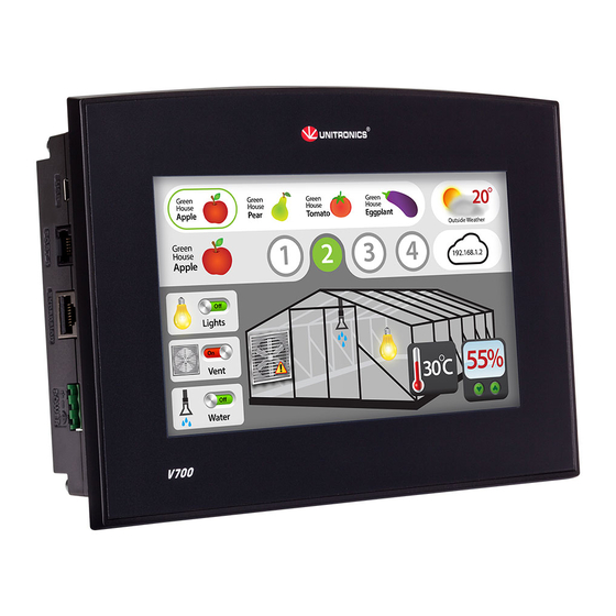
Vision™PLC+HMI
General Description
V700 PLC+HMI is programmable logic controller that comprise a built-in operating panel containing
a 7" Color Touchscreen
I/O Options
Screen
Keypad or
Function Keys
Programming Com
Port, Built-in
RS232/485
Ethernet
USB device,
mini-B
Com Ports,
separate order,
installed by user
* V700 comprises both RS232/485 and USB ports; note that only one channel may be used at a time.
Standard Kit Contents
Controller
Terminal Block
Battery
Mounting Brackets
Rubber Seal
Alert Symbols and General Restrictions
When any of the following symbols appear, read the associated information carefully.
Symbol
Meaning
Danger
Warning
Caution
Caution
Before using this product, the user must read and understand this document.
All examples and diagrams are intended to aid understanding, and do not guarantee operation.
Unitronics accepts no responsibility for actual use of this product based on these examples.
Please dispose of this product according to local and national standards and regulations.
Only qualified service personnel should open this device or carry out repairs.
Failure to comply with appropriate safety guidelines can cause severe injury or property damage.
Do not attempt to use this device with parameters that exceed permissible levels.
To avoid damaging the system, do not connect/disconnect the device when power is on.
Unitronics
Snap-in I/O Modules / I/O Expansion Modules
7" Color Touch
None
Yes
Yes
Yes
The user may install one or both of the following ports:
CANbus port (V100-17-CAN)
RS232/RS485 port (V100-17-RS4/V100-17-RS4X)
Yes
Yes (3 pin)
Yes
Yes (4 parts)
Yes
Description
The identified danger causes physical and property damage.
The identified danger could cause physical and property damage.
Use caution.
Installation Guide
V700-T20BJ
V700-S-T20BJ
1
Advertisement
Table of Contents

Related Manuals for Vision V700-T20BJ

Summary of Contents for Vision V700-T20BJ
-
Page 1: General Description
Installation Guide Vision™PLC+HMI V700-T20BJ V700-S-T20BJ General Description V700 PLC+HMI is programmable logic controller that comprise a built-in operating panel containing a 7” Color Touchscreen I/O Options Snap-in I/O Modules / I/O Expansion Modules Screen 7" Color Touch Keypad or None... -
Page 2: Environmental Considerations
Vision™ Installation Guide Environmental Considerations Do not install in areas with: excessive or conductive dust, corrosive or flammable gas, moisture or rain, excessive heat, regular impact shocks or excessive vibration, in accordance with the standards given in the product’s technical specification sheet. - Page 3 Vision™ Panel Mounting Before you begin, note that the mounting panel cannot be more than 5 mm thick. 1. Make a panel cut-out of the appropriate size: 193x125mm (7.59”x4.92”). 2. Slide the controller into the cut-out, ensuring that the rubber seal is in place.
- Page 4 Vision™ Installation Guide Inserting the Battery In order to preserve data in case of power-off, you must insert the battery. The battery is supplied taped to the battery cover on the rear of the controller. 1. Remove the battery cover shown on page 3.
-
Page 5: Power Supply
Vision™ Power Supply The controller requires either an external 12 or 24VDC power supply. Note: Photo is for illustration purposes only. 1. The power supply must include double insulation. Outputs must be rated as SELV/PELV/Class 2/Limited Power. 2. Use separate wires to connect the functional earth terminal and the 0V terminal to the system earth ground. - Page 6 Vision™ Installation Guide Pinouts The pinouts below show PLC port signals. To connect a PC to a port that is set to RS485, remove the RS485 connector, and connect the PC to the PLC via the programming cable. Note that this is possible only if flow control signals are not used (which is the standard case).
- Page 7 Vision™ Installing a Snap-in I/O Module 1. Remove the I/O connector cap shown on Page 3. 2. Line the circular guidelines on the Snap-in I/O Module with the slots on the controller as shown below. 3 Apply even pressure on all 4 corners until you hear a distinct ‘click’. The module is now installed.
- Page 8 Vision™ Installation Guide The information in this document reflects products at the date of printing. Unitronics reserves the right, subject to all applicable laws, at any time, at its sole discretion, and without notice, to discontinue or change the features, designs, materials and other specifications of its products, and to either permanently or temporarily withdraw any of the forgoing from the market.
Need help?
Do you have a question about the V700-T20BJ and is the answer not in the manual?
Questions and answers