
Related Manuals for iPECS iPECS-MG


Summary of Contents for iPECS iPECS-MG
- Page 1 Quick Start Guide Please read this manual carefully before operating System. Retain it for future reference...
-
Page 2: Table Of Contents
Quick Start Guide Table of Contents 1 SYSTEM OVERVIEW ................1 1.1 iPECS-MG System Connection Diagram ..........1 1.2 System Components .................. 2 2 KSU INSTALLATION ................3 2.1 BKSU/EKSU Unpacking ................3 2.2 Power Supply Unit Installation ..............5 2.3 Frame Ground Connection ................ - Page 3 4.2.1.1 Pin Assignment ......................27 4.2.2 Ferrite Core Installation and Wiring ................28 5 STARTING THE IPECS-MG .............. 30 5.1 Before Starting the iPECS-MG System ........... 30 5.2 Basic Programming .................. 30 5.2.1 Web Admin Programming ..................30 5.2.1.1 How to enter the Web Admin Programming .............. 31 5.2.1.2...
-
Page 4: System Overview
Quick Start Guide 1.1 iPECS-MG System Connection Diagram The following figure shows the components that make up the iPECS-MG System: Figure 1.1 System Connection Diagram... -
Page 5: System Components
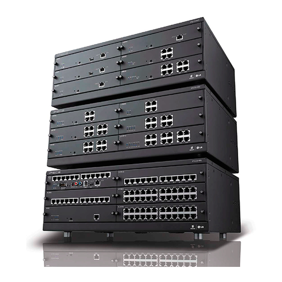
Quick Start Guide 1.2 System Components OPTION ITEM DESCRIPTION BOARD BKSU Basic KSU EKSU Expansion KSU Power Supply Unit (350W) Main Board MPB100 Main Processor Board 100 DSIU Digital and Single Line Interface Unit (Default; 6 DKT, 6 SLT) MODU Modem Unit (Optional;... -
Page 6: Ksu Installation
Quick Start Guide Unpacking BKSU/EKSU Open the box and verify the items shown in Figure 2.1A and 2.1B are included: Figure 2.1A BKSU Carton Contents... - Page 7 Quick Start Guide Figure 2.1B EKSU Carton Contents...
-
Page 8: Power Supply Unit Installation
10.0A 1A(Battery charge) 1. Insert PSU along the guide rails on the rear side of iPECS-MG. 2. Slide and Press PSU to the CN6 on MB and the CN7 on MBE. 3. To fix it securely, turn 4 screws clockwise. -
Page 9: Frame Ground Connection
1m (3.28ft). 2.4 External Backup Battery Installation In case of power failure, the external backup batteries automatically maintain uninterrupted power for the iPECS-MG System. The external batteries must provide 24V DC; this is generally accomplished by connecting two 12V batteries in a series arrangement as shown: Figure 2.4 External Backup Battery Installation... -
Page 10: Ksu Mounting
Quick Start Guide 2.5 KSU Mounting 2.5.1 Wall Mounting / Rack Mounting 1. Attach the mounting template included for accurate placement to the wall and drill the hole. 2. Install 12 anchor plugs into the wall using the mounting template (Figure 2.5.1A). - Page 11 Quick Start Guide Figure 2.5.1B Rack Mounting...
-
Page 12: Expansion Ksu Installation
2. To operate the System, each KSU should be connected using the Expansion cable as shown below. Please make sure that the Expansion cable is connected correctly, and not facing the wrong direction. 3. Connect Fasteners with screws to affix the iPECS-MG system. C9 connector C8 connector Figure 2.6 Expansion KSU installation... -
Page 13: Board Installation
Quick Start Guide 3.1 Installation of the Boards Prior to installing the Boards, the following should be considered: CAUTION • Verify that electrical Power is turned OFF. • To protect the System from static electricity, do not directly touch the boards; to discharge static, touch a grounded object, or wear a grounding strap. -
Page 14: Main Processing Board 100/300 (Mpb100/Mpb300)
Quick Start Guide 3.2 Main Processing Board 100/300 (MPB100/MPB300) The Main Processor Board controls communication between the peripheral Board, supervises all resources in the system, controls the gain adjustment of the PCM signal, generates the System tones, and manages System call processing (MPB300 is shown as an example in Figure 3.2.1). -
Page 15: Mj3 (Alarm Detection And Relay Contact) Pin Assignment
Quick Start Guide 3.2.1.2 MJ3 (Alarm Detection and Relay Contact) Pin Assignment CONNECTOR PIN NUMBER SIGNAL NAME RJ11 ALARM-T ALARM-R Relay-T Relay-R MJ4 Pin Assignment (USB) CONNECTOR PIN NUMBER SIGNAL NAME USB Type A 4 3 2 1 VBUS (+5V) 3.2.2 DSIU (Digital and Single line Interface Unit) -
Page 16: Co Line Boards
3.3.1 LCOB4/LCOB8/LCOB12 (Loop Start CO Line Interface Board) The LCOB (Loop Start CO Interface Board) is a board for PSTN interface on iPECS-MG system. LCOB supports Caller Identification (CID) detection, Polarity Reversal (PR) detection, Call Progress Tone (CPT) detection. But the optional CMU4 board is needed in case of call metering service (50Hz, 12kHz, and 16kHz). -
Page 17: Brib2/Brib4 (Switchable S/T Interface Board)
There are two kinds of BRIB2/BRIB4 according to CPU, but they have the same functions. The BRIB2 supports S-interface (Line card function) or T-interface (Trunk function). iPECS-MG can be positioned at reference point Ia (T) or Ib (S) on ETS that is TE-slave without power feeding or NT-master with power feeding. -
Page 18: Pin Assignment
Quick Start Guide 3.3.2.1 Pin Assignment SIGNAL NAME CONECTOR PIN NUMBER FUNCTION (T-mode) RJ45 1,2,7,8 Reserved Transmit Data Receive Data Receive Data Transmit Data • NOTE Upper side of RJ-45 – S-mode connection, Lower side of RJ-45 – T-mode connection 3.3.2.2 Connectors and Switch Functions... -
Page 19: Prib (Primary Rate Interface Board)
Quick Start Guide 3.3.3 PRIB (Primary Rate Interface Board) There are two kinds of PRIB according to CPU, but they have the same functions. The Primary Rate Interface Board (PRIB) provides one (1) PRI interface, or one (1) E1R2 interface; this interface supports 30 PCM bearer and 2 signaling channels for PRI or E1R2. -
Page 20: Pin Assignment
Quick Start Guide 3.3.3.1 Pin Assignment PRI Port CONNECTOR PIN NUMBER SIGNAL NAME RX-T RJ45 RX-R TX-T TX-R 7, 8 For North America, The PRIB provides one (1) PRI interface or one (1) T1 interface for digital trunk function. -
Page 21: Extension Boards
Quick Start Guide 3.4 Extension Boards 3.4.1 SLIB12/24 (Single Line Interface Board) There are two kinds of SLIB12/24 according to CPU, but they have the same functions. The SLIB12/24 provides 12(24) single line analog ports with FSK ( ITU-T V.23 or Bell 202) or DTMF (ITU-T Q.23) Caller ID function. -
Page 22: Pin Assignment
Quick Start Guide 3.4.1.1 Pin Assignment SLIB12/24 CONNECTOR PIN NUMBER SIGNAL NAME FUNCTION RJ45 1,2,3 Reserved SLT_RX Receive Data SLT_TX Transmit Data 6,7,8 Reserved 3.4.2 SLIB12C/24C (with RJ21 connector) There are two kinds of SLIB12C/24C according to CPU, but they have the same functions. -
Page 23: Dtib12/24 (Digital Terminal Interface Board)
Quick Start Guide 3.4.3 DTIB12/24 (Digital Terminal Interface Board) The connection between the DTIB12/24 and DKT is provided through RJ45 Modular Jacks. • DTIB 12: provide 12 ports • DTIB 24: provide 24 ports DTIB12/24 can be installed on the universal slot in any KSU except the MPB slot of 1 KSU. -
Page 24: Pin Assignment
Quick Start Guide 3.4.4.1 Pin Assignment SLIB12C/24C/DTIB12C/24C CONNECTOR RJ21 PAIR COLOR SLIB/DTIB(12/24C) PORT REMARKS TYPE NUMBER CODE DESIGNATION RJ21 VT-1 BL:BLUE BK:BLACK VR-1 BN:BROWN VT-2 OR:ORANGE VR-2 WH:WHITE VT-3 GN:GREEN VR-3 SL: SILVER VT-4 VI:VIOLET VR-4 RD:RED YL:YELLOW VT-5... -
Page 25: Function Boards
Quick Start Guide 3.5 Function Boards 3.5.1 VMIB/ AAIB (Voice Mail/Auto Attendant Interface Board) The VMIB/AAIB provides system announcement, ACD/UCD announcement, and User Greeting, along with a processor and DSP circuitry to support 8 simultaneous channels. ITEM CHANNEL SYSTEM GREETING/USER GREETING VMIB System Greeting (0.5hrs.), User Message (100 Hours) -
Page 26: Pin Assignment
The VOIB8/VOIB24 provides the Ethernet interface for S/W applications and VoIP features. The VOIB8/24 is used to provide packet relay for remote devices to communicate with the host and translate between the iPECS proprietary protocols and other standard protocols (H323, SIP). -
Page 27: Terminal And Door Phone Models
Quick Start Guide 3.6 Terminal and Door Phone Models Various types of digital terminals and IP Terminals can be used with the iPECS-MG DSIU/DTIB12/DTIB12C/ DTIB24/DTIB24C and with VOIB8/VOIB24 as listed in the following Table: Model Description Model Description LKD-2NS... -
Page 28: Basic Terminal Connection
Quick Start Guide 3.6.2 Basic Terminal Connection 3.6.2.1 DKT The following illustrates how to connect the DKT to your System: Figure 3.6.2 DKT Connection DKT Pin Assignment Connector PIN Number Signal Name RJ11 Reserved TIP, RING 3.6.2.2 SLT The following illustrates how to connect the SLT to your System: Figure 3.6.3 SLT Connection... -
Page 29: Connecting Additional Terminals
Quick Start Guide 3.6.3 Connecting Additional Terminals The MPB100/MPB300 provides connections for one external music source, one external page port, one relay contact, and an alarm detection input monitor through the PJ1 (RED, External MOH) and PJ2 (BLUE, External Page) audio jack and a MJ3 (RJ11 Modular Jack). -
Page 30: Dect Installation
Quick Start Guide 4.1 Introduction The iPECS-MG provides support for the System DECT solution which is composed WTIB4/8, Base Station (GDC- 400B & GDC-600B & GDC-600BE), and DECT terminals (GDC-33xH, 34xH, 4x0H). For installation instructions, refer to the iPECS DECT Installation Guide. -
Page 31: Ferrite Core Installation And Wiring
Ferrite core is provided in the packaging of the Base Station for EMI. The Ferrite core should be installed when the WTIB4/8 is installed in the iPECS-MG system. One Ferrite core is to be used with the line cord between the Base Station and each port of WTIB4/8 (as shown, refer to iPECS-MG Hardware Description and Installation Manual for more detail). - Page 32 Quick Start Guide Figure 4.2.4 Wiring with MDF and connection tab between WTIB4/8 and Base Station NOTE • Even though there are connection points such as MDF or connection tab between WTIB4/8 and Base Station, the connection points should be connected with twisted-pair cable (at least CAT3 class).
-
Page 33: Starting The Ipecs-Mg
- Before programming the System, Switch 1-1 pole should be OFF and then power cycle OFF and ON to initialize the default System database. 2) Plug the AC power cord into the iPECS-MG System and AC outlet. Turn on the iPECS-MG System; after installing the 1st, 2nd and 3rd KSUs, Power-On as follows: KSU ... -
Page 34: How To Enter The Web Admin Programming
Quick Start Guide 5.2.1.1 How to enter the Web Admin Programming 1) In the browser ‘ADDRESS’ field, enter the MPB IP address (default 10.10.10.1), and then the WEB server returns to the WEB Services Home page. 2) On the Home page, click [Admin & Maintenance] to login to the Web-admin. -
Page 35: Web Admin Description
Quick Start Guide 5.2.1.2 Web Admin Description 1. System Boot and Application Software Version with release time. 2. Administration – The Programming menu categories (6) are displayed. Each programming field in category can be accessed by clicking. 3. S/W Upgrade – MPB S/W, Boards S/W, IP-Phone S/W and VMIB Prompt Upgrade. -
Page 36: Vmib Prompt Upgrade
Quick Start Guide 5.2.1.3 VMIB Prompt Upgrade 1. Click [S/W Upgrade] and [VMIB Prompt Upgrade]. 2. Then, the installed VMIB or AAIB and Prompt List are displayed. 3. Check Prompt file to be upgrade and Click [SELECT] button. 4. Select VMIB Slot & Prompt index. -
Page 37: Slt Line Monitoring
Quick Start Guide 5.2.1.4 SLT Line Monitoring 1. Click [System Management], [Trace] and [SLT Line Monitor]. 2. Then, installed SLTs are displayed. 3. Select ‘Check Line Monitor’ and Click [Do Line Monitor] button. 4. To check the result, click [SLT Line Monitor] again. -
Page 38: Dkt Programming
Quick Start Guide 5.2.2 DKT Programming 5.2.2.1 How to Enter Programming Mode To enter programming mode, perform the following Steps: 1. Lift handset or press the [MON] button on the ADMIN station; the ICM dial tone (optional) will be presented. -
Page 39: Pre-Programming (Pgm100-108)
Quick Start Guide 5.2.2.4 Pre-programming (PGM100-108) For more detailed information on Pre-programming, refer to the iPECS-MG Description and installation manual. Location PGM-Nation Code (PGM100) When programming, the ‘MODE’ switch on the MPB100/300 should be set to OFF. Nation Code Listing... -
Page 40: Flexible Numbering Plan (Pgm 110-115)
Quick Start Guide PRIB(T1) DCOB(T1) Logical Slot Assignment (PGM 103) The following items are for programming the logical slot numbers in use. NOTE • After PGM101 and PGM103 are completed by the user, the System should be reset. Code... - Page 41 Quick Start Guide DEFAULT VALUE INDEX ITEM (Numbering Plan Type 1) Conference Room 4 Conference Room 5 Conference Room 6 Conference Room 7 Conference Room 8 Conference Room 9 Internal Page Personal VM Page Announcement Page For Attendant Page Auto Answer...
- Page 42 Quick Start Guide DEFAULT VALUE INDEX ITEM (Numbering Plan Type 1) Call Based CLIR CLIR Access COLR Access Pilot Hunt Call Command Call Oneway Command Call Conf Intrude Register Camp On Register OHVO Register Mobile Num Register Mobile CLI Register...
-
Page 43: System Time And Date Setting (Pgm233)
Quick Start Guide 5.2.2.6 System Time and Date Setting (PGM233) At Admin programming mode: Press the [TRANS/PGM] button + 233. Press the FLEX 1 Button (Time). Enter 2 digits for hour and 2 digits for minutes (HHMM as 24 Hour format. For example, 1530 for 3:30 PM). -
Page 44: Troubleshooting
Quick Start Guide Problem Cause/Symptom Solution Check the AC Power source. Check the Inlet fuse and PSU Fuse. AC Power Fail Check LD21 and LD22 on MB/MBE. Replace the PSU with a good one. System power failure Check MPB board was installed and...
Need help?
Do you have a question about the iPECS-MG and is the answer not in the manual?
Questions and answers