
Subscribe to Our Youtube Channel
Related Manuals for KEP SUPERtrol II


Summary of Contents for KEP SUPERtrol II
- Page 1 SUPERtrol II omputer hird diTion KESSLER-ELLIS PRODUCTS 10 Industrial Way East Eatontown, NJ 07724 800-631-2165 • 732-935-1320 Fax: 732-935-9344 http://www.kep.com 99589 04/20/16...
-
Page 3: Table Of Contents
SUPERtrol II Flow Computer CONTENTS SAFETY INSTRUCTIONS ......................1 1. INTRODUCTION 1.1 Unit Description ......................2 1.2 Specifications ....................... 3 2. INSTALLATION 2.1 General Mounting Hints ....................8 2.2 Mounting Diagrams ...................... 8 3. APPLICATIONS 3.1 Steam Mass ........................ 13 3.2 Steam Heat ......................... - Page 4 10.8 Misc. Tab ........................ 106 11. GLOSSARY OF TERMS 10 Glossary Of Terms ..................... 107 12. Diagnosis and Troubleshooting 12.1 Response of SUPERtrol II on Error or Alarm ............110 12.2 Diagnosis Flowchart and Troubleshooting .............. 110 12.3 Error Messages .......................111 Appendix A Fluid Properties Table .....................
-
Page 5: Safety Instructions
SUPERtrol II Flow Computer SAFETY INSTRUCTIONS The following instructions must be observed. • This instrument was designed and is checked in accordance with regulations in force EN 60950 (“Safety of information technology equipment, including electrical business equipment”). A hazardous situation may occur if this instrument is not used for its intended purpose or is used incorrectly. -
Page 6: Introduction
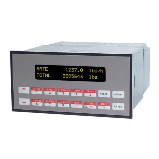
Multiple flow equations are The peak demand option for the SUPERtrol II is intended for available in a single instrument with many advanced features. applications where it is important to compute such an hourly... -
Page 7: Specifications
SUPERtrol II Flow Computer 1.2 Specifications: Analog Input: Ranges Environmental Voltage: 0-10 VDC, 0-5 VDC, 1-5 VDC Operating Temperature: 0 to +50 C Current: 4-20 mA, 0-20 mA Storage Temperature: -40 to +85 C Basic Measurement Resolution: 16 bit Humidity : 0-95% Non-condensing... - Page 8 SUPERtrol II Flow Computer Datalogger (optional) Analog Outputs Type: Battery Backed RAM The analog output usage is menu assignable to correspond Size: 64k to the Heat Rate, Uncompensated Volume Rate, Corrected Initiate: Key, Interval or Time of Day Volume Rate, Mass Rate, Temperature, Density, or Items Included: Selectable List Pressure.
- Page 9 SUPERtrol II Flow Computer Step 3 : Compute the Volumetric Flow- In the setup menu, the flow computer activates the correct Volumetric flow is the term given to the flow in volume units. setup variables based on the instrument configuration, the...
- Page 10 Read the maximum number of records capacity of the menu. datalogger Move Pointer Back N records The SUPERtrol II will warn the operator of a TRAP ERROR Dump Record at Pointer when an abnormal condition is detected. The error can be Dump records newer than pointer acknowledged by pressing the ENTER key.
- Page 11 Poll the SUPERtrol II unit for information from a remote The particular error conditions to call out on must be Call Out from the SUPERtrol II unit to a remote PC on a defined in the ERROR MASK The NUMBER OF REDIALS to be attempted if line is...
-
Page 12: Installation
2.1 General Mounting Hints: General Mounting Hints The SUPERtrol II Flow Computer should be located in an area with a clean, dry atmosphere which is relatively free of shock and vibration. The unit is installed in a 5.43" (138mm) wide by 2.68" (68mm) high panel cutout. (see Mounting Dimensions) To mount the Flow Computer, proceed as follows: a. - Page 13 SUPERtrol II Flow Computer 2.2 Mounting Diagrams: (continued) Wall Mount (mounting option W) 9.4 (238) 4.13 (105) Security Tag Provisions 0.385 2.33 (59) (9.8) 8.4 (213.4) 0.59 (15) 0.625”ø 0.75”ø 5 places 0.75” Conduit Knockouts (5 places) 1.10 1.10 1.10 1.10...
- Page 14 SUPERtrol II Flow Computer 2.2 Mounting Diagrams: (continued) Explosion Proof Mount (mounting option E)
-
Page 15: Applications
SUPERtrol II Flow Computer 3. Applications STEAM MASS 3.1 Steam Mass Measurements: A flowmeter measures the actual volume flow in a steam line. A temperature and/or pressure sensor is installed to measure temperature and/or pressure. Calculations: • Density and mass flow are calculated using the steam tables stored in the flow computer. -
Page 16: Steam Heat
SUPERtrol II Flow Computer STEAM HEAT 3.2 Steam Heat Measurements: A flowmeter measures the actual volume flow in a steam line. A temperature and/or pressure sensor is installed to measure temperature and/or pressure. Calculations: • Density, mass flow and heat flow are calculated using the steam tables stored in the flow computer. -
Page 17: Steam Mass
SUPERtrol II Flow Computer STEAM NET HEAT 3.3 Steam Net Heat Measurements: A flowmeter measures the actual volume flow in a steam line. A temperature and a pressure sensor are installed to measure temperature and/or pressure. All measurement are made on the steam side of a heat exchanger. -
Page 18: Steam Delta Heat
SUPERtrol II Flow Computer STEAM DELTA HEAT 3.4 Steam Delta Heat Measurements: Measures actual volume flow and pressure of the saturated steam in the supply piping as well as the temperature of the condensate in the downstream piping of a heat exchanger. -
Page 19: Corrected Gas Volume
SUPERtrol II Flow Computer CORRECTED 3.5 Corrected Gas Volume GAS VOLUME Measurements: A flowmeter measures the actual volume flow in a gas line. Temperature and pressure sensors are installed to correct for gas expansion effects. Calculations: • Corrected Volume is calculated using the flow, temperature and pressure inputs as well as the gas characteristics stored in the flow computer (see "FLUID DATA"... -
Page 20: Gas Mass
SUPERtrol II Flow Computer GAS MASS 3.6 Gas Mass Measurements: A flowmeter measures the actual volume flow in a gas line. Temperature and pressure sensors are installed to measure temperature and pressure. Calculations: • Density and mass flow are calculated using gas characteristics stored in the flow computer. -
Page 21: Gas Combustion Heat
SUPERtrol II Flow Computer GAS COMBUSTION 3.7 Gas Combustion Heat Measurements: HEAT A flowmeter measures the actual volume flow in a gas line. Temperature and pressure sensors are installed to measure temperature and pressure. Calculations: • Density, mass flow and combustion heat are calculated using gas characteristics stored in the flow computer. -
Page 22: Corrected Liquid Volume
SUPERtrol II Flow Computer Corrected 3.8 Corrected Liquid Volume Liquid Volume Measurements: A flowmeter measures the actual volume flow in a liquid line. A temperature sensor is installed to correct for liquid thermal expansion. A pressure sensor can be installed to monitor pressure. -
Page 23: Liquid Mass
SUPERtrol II Flow Computer Liquid Mass 3.9 Liquid Mass Measurements: Actual volume flow is measured by the flow element (DP transmitter, Flowmeter). Temperature is measured by the temperature transmitter. A pressure transmitter can be used to monitor pressure. Pressure measurement does not affect the calculation. A density transmitter may be used in place of a temperature transmitter for direct density measurement. -
Page 24: Liquid Combustion Heat
SUPERtrol II Flow Computer LIQUID COMBUSTION 3.10 Liquid Combustion Heat HEAT Measurements: Actual volume flow is measured by the flow element (DP transmitter, Flowmeter). Temperature is measured by the temperature transmitter. A pressure transmitter can be used to monitor pressure. Pressure measurement does not affect the calculation. -
Page 25: Liquid Sensible Heat
SUPERtrol II Flow Computer LIQUID SENSIBLE 3.11 Liquid Sensible Heat HEAT Measurements: Actual volume flow is measured by the flow element (DP transmitter, Flowmeter). Temperature is measured by the temperature transmitter. A pressure transmitter can be used to monitor pressure. Pressure measurement does not affect the calculation. -
Page 26: Liquid Delta Heat
SUPERtrol II Flow Computer LIQUID DELTA HEAT 3.12 Liquid Delta Heat Measurements: Actual volume flow is measured by the flow element (DP transmitter, Flowmeter). Temperature of the supply and return lines are measured by the temperature transmitters. Calculations: • The density, mass flow and delta heat are calculated using values of the heat carrying liquid stored in the flow computer. -
Page 27: Steam - Condensate Heat
SUPERtrol II Flow Computer STEAM – 3.13 Steam – Condensate Heat CONDENSATE Measurements: ENERGY METER Actual condensate volume flow is measured by the flow element (DP transmitter, Flowmeter). Condensate temperature is measured by the temperature transmitter. A pressure transmitter is used to monitor steam pressure. -
Page 28: Wiring
SUPERtrol II Flow Computer 4. WIRING 4.1 Terminal Designations Two Relay Terminations Three Relay Option Terminations DC OUTPUT DC OUTPUT FLOW FLOW PULSE IN Vin (+) PULSE IN Vin (+) - - - - - - - - - -... -
Page 29: Typical Wiring Connections
SUPERtrol II Flow Computer 4.2 Typical Wiring Connections: 4.2.1 Flow Input Analog 4-20 mA Transmitter (+) 24 V Out 4-20 (i.e. DP Transmitter) – 4-20 mA In Analog Voltage Transmitter (+) V In (i.e. Turbine Flowmeter with F/V Converter) –... -
Page 30: Temperature Input
SUPERtrol II Flow Computer 4.2.4 Temperature Input * Or optional steam trap monitoring input in some saturated steam applications. 4.2.5 Temperature 2 Input... -
Page 31: Wiring In Hazardous Areas
SUPERtrol II Flow Computer 4.3 Wiring In Hazardous Areas Examples using MTL787S+ Barrier (MTL4755ac for RTD) 4.3.1 Flow Input Hazardous Area Safe Area DP Transmitter 24V Out 4-20mA In Common 4.3.2 Pressure Input Hazardous Area Safe Area Common 24V Out... -
Page 32: Unit Operation
SUPERtrol II Flow Computer 5. UNIT OPERATION 5.1 Front Panel Operation Concept for Operate Mode HELP How To Use On-Line Help On-line help is provided to assist the operator in using this product. The help is available during OPERATE and SETUP modes simply by pressing the HELP key. The HELP key is used to enter decimals when entering numeric values. -
Page 33: General Operation
SUPERtrol II Flow Computer 5.2 General Operation General Operation This instrument is used primarily to monitor flowrate and accumulated total. The inputs can be software configured for a variety of flowmeter, temperature and pressure sensors. The standard output types include: Pulse, Relay, Analog and RS-232 The unit can display the flowrate, total and process variables. -
Page 34: Serial Port Operation
In this mode of operation the RS232 port is assumed connected to a computer. The SUPERtrol II will act as a slave and answer requests from the PC. See the Universal Protocol Users Manual for a complete listing of the commands set supported. -
Page 35: Programming
6. PROGRAMMING 6.1 Front Panel Operation Concept for Program Mode The SUPERtrol II is fully programmable through the front panel. The instrument setup menu structure is based on a number of topical submenu groups with one submenu group for each instrument function. Each submenu contains all of the individual settings associated with that function. -
Page 36: Ez Setup
SUPERtrol II Flow Computer EZ SETUP SETUP EZ SETUP The EZ Setup routine is a quick and easy way to configure the most commonly used instrument functions. We recommend first completing the EZ Setup routine for the flow equation and meter type for your initial application. - Page 37 SUPERtrol II Flow Computer EZ SETUP SETUP (Continued) Select the type of fluid appropriate for your application. Fluid Type Selection: SATURATED STEAM, SUPERHEATED STEAM Display: SATURATED STEAM FLUID TYPE Select the flowmeter type used in your application. FLOWMETER TYPE Selection: LINEAR, SQR LAW, SQR LAW-LIN., LINEAR 16 PT, SQR...
-
Page 38: Detailed Menu Descriptions
SUPERtrol II Flow Computer EZ SETUP SETUP (Continued) FULL SCALE VALUE Enter the full scale value for the pressure input signal. (PRESSURE) Input: Number with fixed decimal point: 000.000 ... 999.999 Display: 580.000 psia FULL SCALE VALUE DEFAULT VALUE Enter the default value for the pressure input signal. -
Page 39: System Parameters
SUPERtrol II Flow Computer SYSTEM PARAMETERS SYSTEM PARAMETERS The EZ Setup routine is a quick and easy way to EZ SETUP configure the most commonly used instrument functions. Reference: Refer to Section 6.2 for EZ Setup Programming. Caution: Entering the EZ Setup mode automatically sets many features to default values without informing the user. - Page 40 SUPERtrol II Flow Computer SYSTEM PARAMETERS SYSTEM PARAMETERS (Continued) FLOW EQUATION The Flow Equation sets the basic functionality of the unit. Choose the Flow Equation for your particular application. Note: Various setup data is only available depending on the flow equation selected.
- Page 41 SUPERtrol II Flow Computer SYSTEM PARAMETERS SYSTEM PARAMETERS (Continued) ENTER TIME Enter the actual time in this format: Hours - Minutes Note: After prolonged breaks in the power supply (several days) or upon initial start-up of the unit, the date and time must be reset.
- Page 42 SUPERtrol II Flow Computer SYSTEM PARAMETERS SYSTEM PARAMETERS (Continued) ENGINEERING CODE A personal enginerring code may be defined. This code is used to enable program menus that are normally reserved for engineering Note: personnel. The Engineering Code will (i.e.: Service & Analysis Submenu Group)
- Page 43 SUPERtrol II Flow Computer SYSTEM PARAMETERS SYSTEM PARAMETERS (Continued) ORDER CODE The order code (part number) of the unit can be entered. This will help in identifying what options were ordered. Note: • The order number is set at the factory and should only be altered if options are added in the field by an authorized service technician.
-
Page 44: Display
SUPERtrol II Flow Computer DISPLAY DISPLAY SCROLL LIST Select the variable that are to be displayed in the "HOME position" during normal operation. Each variable can be assigned to line 1 (L1), line 2 (L2) or NO (removed from scroll list). - Page 45 SUPERtrol II Flow Computer DISPLAY DISPLAY (Continued) MAX. DEC. POINT Enter the number of decimal places for numerical values. Note: • The number of decimal places applies to all displayed variables and totalizers. • The number of decimal places is automatically reduced if there is insufficient space available on the display for large numbers.
-
Page 46: System Units
SUPERtrol II Flow Computer SYSTEM UNITS SYSTEM UNITS TIME BASE Select "one" unit of time to be used as a reference for all measured or derived and time-dependant process variables and functions such • flowrate (volume/time; mass/time) • heat flow (amount of energy/time) etc. - Page 47 SUPERtrol II Flow Computer SYSTEM UNITS SYSTEM UNITS (Continued) MASS FLOW UNIT Select the unit of mass flowrate (mass/time base). Note: The unit selected here also applies to the following: • Zero and full scale value for current • Relay setpoints...
- Page 48 SUPERtrol II Flow Computer SYSTEM UNITS SYSTEM UNITS (Continued) COR.VOL. Select the unit of corrected volumetric flowrate FLOW UNIT (corrected volume/time base). Note: The unit selected here also applies to the following: • Zero and full scale value for current •...
- Page 49 SUPERtrol II Flow Computer SYSTEM UNITS SYSTEM UNITS (Continued) VOLUME FLOW UNIT Select the unit for volumetric flowrate. Note: The unit selected here also applies to the following: • Zero and full scale value for current • Relay setpoints Selection: The available selections will change depending on the flow equation selected.
- Page 50 SUPERtrol II Flow Computer SYSTEM UNITS SYSTEM UNITS (Continued) DEFINITION bbl In certain countries the ratio of gallons (gal) per barrels (bbl) can vary according to the fluid used and the specific industry. Select one of the following definitions: • US or imperial gallons •...
- Page 51 SUPERtrol II Flow Computer SYSTEM UNITS SYSTEM UNITS (Continued) PRESSURE UNIT Select the unit for process pressure. Note: The unit selected here also applies to the following: • Zero and full scale value for current • Relay setpoints • Reference conditions Differential pressure is in mbar for Metric selections Differential pressure is in "H...
- Page 52 SUPERtrol II Flow Computer SYSTEM UNITS SYSTEM UNITS (Continued) SPEC. ENTHALPY Select the unit for the combustion value (spec. enthalpy). UNIT Note: The unit selected here also applies to the following: • Specific thermal capacity (kWh/kg → kWh/kg - °C)
-
Page 53: Fluid Data
SUPERtrol II Flow Computer FLUID DATA FLUID DATA FLUID TYPE Select the fluid. There are three types: 1. Steam / Water All information required for steam and water (such as saturated steam curve, density and thermal capacity) is permanently stored in the flow computer. - Page 54 SUPERtrol II Flow Computer FLUID DATA FLUID DATA (Continued) THERM. EXP. COEF. Enter the thermal expansion coefficient for a generic liquid. The coefficient is required for the temperature compensation of volume with various flow equations (i.e. Liquid Mass or Corrected Liquid Volume).
- Page 55 SUPERtrol II Flow Computer FLUID DATA FLUID DATA (Continued) FLOW. Z-FACTOR Enter a Z-factor for the gas at operating conditions. The Z-factor indicates how different a "real" gas behaves from an "ideal gas" which exactly obeys the "general gas law" (P x V/T = constant;...
- Page 56 SUPERtrol II Flow Computer FLUID DATA FLUID DATA (Continued) MOLE % NITROGEN Enter the Mole % Nitrogen in the anticipated natural gas mixture. This information is needed by the NX-19 computation Note: Select "NATURAL GAS (NX-19)" in "FLUID TYPE" to activate this function.
- Page 57 SUPERtrol II Flow Computer FLUID DATA FLUID DATA (Continued) VISCOSITY COEF. B Enter the Viscosity coefficient B for the anticipated fluid. This information is needed by the viscosity computation for UVC and for Reynolds Number calculations. Note: Select "SQUARE LAW 16PT" or "LINEAR UVC" in "FLOWMETER TYPE"...
-
Page 58: Flow Input
SUPERtrol II Flow Computer FLOW INPUT FLOW INPUT FLOWMETER TYPE Select the flowmeter type. The flow equation (see SYSTEM PARAMETERS) and the flowmeter selected here determine the basic operation of the flow computer. Selection: LINEAR Volumetric flowmeter with linear pulse or analog output. - Page 59 SUPERtrol II Flow Computer FLOW INPUT FLOW INPUT (Continued) SQUARE LAW Select the type of square law flowmeter to be used with the FLOWMETER instrument. Note: This selection will only appear if one of the Square Law selections were made in "FLOWMETER TYPE".
- Page 60 SUPERtrol II Flow Computer FLOW INPUT FLOW INPUT (Continued) Set the low scale value for the analog input signal. LOW SCALE The value entered here must be identical to the value set for the flowmeter. Note: • For flowmeters with analog/linear output, the flow computer uses the selected system units for volumetric flowrate.
- Page 61 SUPERtrol II Flow Computer FLOW INPUT FLOW INPUT (Continued) FULL SCALE-HI ll scale value for the high range transmitter analog input signal. RANGE The value entered here must be identical to the value set for the flowmeter. Note: • The units for differential pressure flowmeters are dependent...
- Page 62 SUPERtrol II Flow Computer FLOW INPUT FLOW INPUT (Continued) K-FACTOR Enter the K-Factor of the flowmeter. Note: • The K-Factor is expressed in pulses per unit volume (as defined by "total units") Input: Number with floating decimal point: 0.001...999999 Display: .000 ft3/h...
- Page 63 SUPERtrol II Flow Computer FLOW INPUT FLOW INPUT (Continued) METER EXP. COEF. The flowmeter pipe expands depending on the temperature of the fluid. This affects the calibration of the flowmeter. This submenu allows the user to enter an appropriate correction factor.
- Page 64 SUPERtrol II Flow Computer FLOW INPUT FLOW INPUT (Continued) DP FACTOR The DP-Factor describes the relationship between the flowrate and the measured differential pressure. The flowrate is computed according to one of the three following equations, depending on the selected flow...
- Page 65 SUPERtrol II Flow Computer FLOW INPUT FLOW INPUT (Continued) DP FACTOR The DP-Factor (K ) can be entered manually or the flow computer (Continued) can compute it for you. The information necessary for this calculation can be found on the sizing sheet from a flowmeter sizing program.
- Page 66 SUPERtrol II Flow Computer FLOW INPUT FLOW INPUT (Continued) DP FACTOR The flow computer will then compute the gas expansion factor (Continued) (ε ), (Y ) using one of the following equation: Orifice Case: ∆p = 1 – (0.41 + 0.35 β...
- Page 67 SUPERtrol II Flow Computer FLOW INPUT FLOW INPUT (Continued) DP FACTOR The DP-Factor (K ) is then computed using one of the following (Continued) equations: Steam: M • (1 – K • (T – T • √2 • ∆p • ρ...
- Page 68 SUPERtrol II Flow Computer FLOW INPUT FLOW INPUT (Continued) With many flowmeters, the relationship between the flowrate and the LINEARIZATION output signal may deviate from an ideal curve (linear or squared). The flow computer is able to compensate for this documented deviation using a linearization table.
- Page 69 SUPERtrol II Flow Computer FLOW INPUT FLOW INPUT (Continued) FLOWMETER Enter the Flowmeter Location LOCATION Selection: Hot, Cold: Display: COLD FLOWMETER LOCATION Enter the Bypass Calibration Factor. BYPASS CAL. FACTOR Input: Max. 6 digit number: 0.000001...999999 Display: 1.000000 BYPASS CAL. FACTOR BYPASS EAm Enter the Bypass EAm Factor.
-
Page 70: Other Input
SUPERtrol II Flow Computer OTHER INPUT OTHER INPUT SELECT INPUT In addition to the flow input, the flow computer provides two other inputs for temperature, density and/or pressure signals. In this submenu, select the particular input which is to be configured in the following submenus. - Page 71 SUPERtrol II Flow Computer OTHER INPUT OTHER INPUT (Continued) LOW SCALE VALUE Set the low scale value for the analog current input signal (value for 0 or 4 mA input current). The value entered here must be identical to the value set in the pressure, temperature or density transmitter.
- Page 72 SUPERtrol II Flow Computer OTHER INPUT OTHER INPUT (Continued) BAROMETRIC PRESS. Enter the actual atmospheric pressure. When using gauge pressure transmitters for determining gas pressure, the reduced atmospheric pressure above sea level is then taken into account. Input: Number with floating decimal point: 0.0000...10000.0...
-
Page 73: Pulse Output
SUPERtrol II Flow Computer 6.10 PULSE OUTPUT PULSE OUTPUT Assign the pulse output to a measured or calculated totalizer value. ASSIGN PULSE OUT- Selection: HEAT TOTAL, MASS TOTAL, CORRECTED VOL. TOTAL, ACTUAL VOLUME TOTAL Display: ACTUAL VOLUME TOTAL ASSIGN PULSE OUTPUT... - Page 74 SUPERtrol II Flow Computer 6.10 PULSE OUTPUT PULSE OUTPUT (Continued) PULSE TYPE The pulse output can be configured as required for an external device (i.e. remote totalizer, etc.). ACTIVE: Internal power supply used (+24V). PASSIVE: External power supply required. POSITIVE: Rest value at 0V (active high).
- Page 75 SUPERtrol II Flow Computer 6.10 PULSE OUTPUT PULSE OUTPUT (Continued) PULSE VALUE Define the flow quantity per output pulse. This is expressed in units per pulse (i.e. ft / pulse). Note: Ensure that the max. flowrate (full scale value) and the pulse value entered here agree with one another.
-
Page 76: Current Output
SUPERtrol II Flow Computer 6.11 CURRENT OUTPUT CURRENT OUTPUT SELECT OUTPUT Select the current output to be configured. The flow computer offers two current outputs. Selection: 1 (Current output 1) 2 (Current output 2) Display: SELECT OUTPUT ASSIGN CURRENT Assign a variable to the current output. - Page 77 SUPERtrol II Flow Computer 6.11 CURRENT OUTPUT CURRENT OUTPUT (Continued) TIME CONSTANT Select the time constant to determine whether the current output signal reacts quickly (small time constant) or slowly (large time constant) to rapidly changing values (i.e. flowrate). The time constant does not affect the behavior of the display.
-
Page 78: Relays
SUPERtrol II Flow Computer 6.12 RELAYS RELAYS SELECT RELAY Set relay output to be configured. Two or three relay outputs are available. Selection: 1 (Relay 1) 2 (Relay 2) 3 (Relay 3, optional) Display: SELECT RELAY Both relays (1 and 2, and optional 3rd relay) can be assigned to... - Page 79 SUPERtrol II Flow Computer 6.12 RELAYS RELAYS (Continued) RELAY MODE Set when and how the relays are switched "ON" and "OFF". This defines both the alarm conditions and the time response of the alarm status. Selection: HI ALARM, FOLLOW LO ALARM, FOLLOW...
- Page 80 SUPERtrol II Flow Computer 6.12 RELAYS RELAYS (Continued) PULSE VALUE Define the flow quantity per output pulse if the relay is configured for "RELAY PULSE OUTPUT".. This is expressed in units per pulse (i.e. ft / pulse). Note: Ensure that the max. flowrate (full scale value) and the pulse value entered here agree with one another.
- Page 81 SUPERtrol II Flow Computer 6.12 RELAYS RELAYS (Continued) HYSTERESIS Enter a hysteresis value to ensure that the "ON" and "OFF" switchpoints have different values and therefore prevent continual and undesired switching near the limit value. Input: Number with floating decimal point: 0.000...999999...
-
Page 82: Communication
SUPERtrol II Flow Computer 6.13 COMMUNICATION COMMUNICATION (Continued) RS-232 USAGE The flow computer can be connected via RS-232 interface to a personal computer or printer. Selection: COMPUTER, PRINTER, MODEM Display: COMPUTER RS-232 USAGE DEVICE ID Enter the unique unit I.D. tag number for the flow computer if a number of flow computers are connected to the same interface. - Page 83 SUPERtrol II Flow Computer 6.13 COMMUNICATION COMMUNICATION (Continued) PRINT LIST Select the variables or parameters which are to be logged or printed via the RS-232 interface. Selection (Procedure): CHANGE? NO CHANGE? YES If YES selected, the available variables are displayed one after another.
- Page 84 SUPERtrol II Flow Computer 6.13 COMMUNICATION COMMUNICATION (Continued) PRINT INITIATE Datalogger and/or printing variables and parameters over the serial RS-232 interface can be initiated at regular intervals (INTERVAL) or daily at a fixed time (TIME OF DAY) or by front key depression.
- Page 85 SUPERtrol II Flow Computer 6.13 COMMUNICATION COMMUNICATION (Continued) SEND INC. TOT. ONLY Select YES or NO for Send Inc. Tot. Only Selection: YES - Unit will send Inc. Tot. Only NO - Unit will not send Inc. Tot. Only Display: SEND INC.
- Page 86 SUPERtrol II Flow Computer 6.13 COMMUNICATION COMMUNICATION (Continued) MODEM AUTO Select YES or NO for Modem Auto Answer ANSWER (Modem) Selection: YES - Modem will answer incoming calls. NO - Modem will not answer incoming calls. Display: MODEM AUTO ANSWER CALL OUT NO Define a Call Out Number.
- Page 87 SUPERtrol II Flow Computer 6.13 COMMUNICATION COMMUNICATION (Continued) HANG UP IF INACTIVE Select YES or NO for Hang Up If Inactive (Modem) Selection: YES - Unit will hang up if remote PC fails to respond within several minutes after connection is established.
- Page 88 SUPERtrol II Flow Computer 6.13 COMMUNICATION COMMUNICATION (Continued) ERROR MASK Select YES or NO for Change Error Mask? prompt (Modem) Selection: YES, NO Display: 00:00 CALL OUT TIME If YES selected, define the conditions that you wish to call out on. The possible conditions are displayed one after another.
-
Page 89: Network Card
SUPERtrol II Flow Computer 6.14 NETWORK CARD NETWORK CARD PROTOCOL The flow computer can be connected via RS-485 interface to a personal computer and communicate via Modbus RTU protocol. Selection: MODBUS RTU Display: MODBUS RTU PROTOCOL DEVICE ID Enter the unique unit I.D. tag number for the flow computer if a number of flow computers are connected to the same interface. -
Page 90: Service & Analysis
SUPERtrol II Flow Computer 6.15 SERVICE & ANALYSIS SERVICE & ANALYSIS EXAMINE AUDIT Two counters contain the number of times the calibration and/or TRAIL configuration parameters have been changed. Changes in important calibration and configuration data are registered and displayed ("electronic stamping"). - Page 91 SUPERtrol II Flow Computer 6.15 SERVICE & ANALYSIS SERVICE & ANALYSIS (Continued) PERFORM This feature allows the calibration of the units inputs and outputs. CALIBRATION CAUTION: NOTE: The calibration should only be performed by qualified technicians. This menu item will only The calibration procedure requires the use of precision Voltage &...
- Page 92 SUPERtrol II Flow Computer 6.15 SERVICE & ANALYSIS SERVICE & ANALYSIS (Continued) CURRENT INPUT Connect your current source to (+) Pin 7 and (-) Pin 4. CALIBRATION (continued) LEARN Apply 0.0 mA. Press enter to learn 0.0 mA. 0.0 mA...
- Page 93 SUPERtrol II Flow Computer 6.15 SERVICE & ANALYSIS SERVICE & ANALYSIS (Continued) ANALOG OUTPUT 1 Connect your Ammeter (current meter) to (+) Pin 14 and (-) Pin 16. CALIBRATION (Pins 14 & 16) Observe the reading on the ammeter. Using the numeric keys, enter 4 mA the actual reading (in mA) and press enter.
- Page 94 SUPERtrol II Flow Computer 6.15 SERVICE & ANALYSIS SERVICE & ANALYSIS (Continued) RELAY TEST Using the ohmmeter, check continuity between pins (17 & 18) and 18 & 19 while turning ON & OFF Relay 1 using the up/down arrow keys.
- Page 95 SUPERtrol II Flow Computer 6.15 SERVICE & ANALYSIS SERVICE & ANALYSIS (Continued) PRINT SYSTEM SETUP This feature allows the units setup parameters to be printed to a connected printer. Display: PRINT SYSTEM SETUP SELF CHECK This feature starts the self-test of the flow computer. A test is internally conducted on the EEPROM, A/D Converter, Time/Date clock, Display and several other hardware circuits.
-
Page 96: Principle Of Operation
Head class flowmeters are supplied by the manufacturers with a 4-20 mA output span which is already in flow units. The SUPERtrol II permits the user to enter this flow- meter information directly. However, closely associated with this information is the density that was assumed during flowmeter calibration. -
Page 97: Pressure Computation
SUPERtrol II Flow Computer 7.3.2 Pressure Input: Pressure Computation General Case Pf = [% input span • (Pres full scale - Pres low scale ] + Pres low scale Gauge Case Pf = Pf + Barometric Manual Case or In Event of Fault Pf = Pressure Default Value 7.3.3... -
Page 98: Corrected Volume Flow Computation
SUPERtrol II Flow Computer 7.3.4 Viscosity (cP) Computation: Density/Viscosity Computation Liquid Case NOTE: (continued) viscosity (in cP) Viscosity cS = cP viscosity = A • exp flowing density ( Tf + 459.67) density of water @ 4°C Gas Case cP viscosity = A • ( Tf + 459.67) -
Page 99: Mass Flow Computation
SUPERtrol II Flow Computer 7.3.5 After calculating the adjusted pressure and temperature, the mixture’s pressure and tempera- ture correlations parameters are calculated by Corrected P = P + 14.7 Volume Flow 1000 Computation The compressibility factor is then calculated by first determining (continued) m = 0.0330378T... -
Page 100: Heat Flow Computation
SUPERtrol II Flow Computer 7.3.8 Heat Flow Computation: Heat Flow Computation Steam Heat heat flow = mass flow • total heat steam(Tf, Pf) Steam Net Heat heat flow = mass flow • [total heat steam(Tf, Pf) - heat saturated water(Pf)] Steam Delta Heat heat flow = mass flow •... - Page 101 SUPERtrol II Flow Computer V-Cone Case 7.3.11 Expansion Factor Computation for NOTE: Y=1 for noncompressible uids (e.g. water, oil etc.). Square Law Flowmeters P / 27.7 (Continued) − β (0.649 0.696 ⋅ ∆ Note that can be in any units as long as they are the same.
- Page 102 SUPERtrol II Flow Computer Accelabar Case 7.3.11 Expansion Factor For 1 inch Accelabar Body Computation for Square Law 9824 5890 Flowmeters (Continued) For 2 inch Accelabar Body...
-
Page 103: Uncompensated Flow Computation
SUPERtrol II Flow Computer 7.3.12 Uncompensated Flow Computation: Uncompensated Flow Computation Pulse, Linear Case input frequency • Time Scaling Factor volume flow = K-Factor • [1 - Meter Exp.Coeff. • ( Tf - T Analog, Linear Case Measured Input Flow volume flow = [1 - Meter Exp.Coeff. -
Page 104: Ilva Flow Meter Equations
SUPERtrol II Flow Computer 7.3.13 ILVA Flow Meter ILVA Flowmeter - This meter type requires an initial linearization using the lineariza- Equations tion table. In addition, the following specialized corrections are required. Y = 1 – (115.814 • (dp / p) • 0.0001) -
Page 105: Computation Of The Dp Factor
SUPERtrol II Flow Computer 7.4 Computation of the DP Factor It is assumed that the user has the printout from a standardized sizing program for the particular device he will be using. Such standardized printouts list all the necessary information which the user will then be prompted for by the instrument or diskette. -
Page 106: Serial Port
SUPERtrol II Flow Computer 8. RS-232 Serial Port 8.1 RS-232 Port Description: The SUPERtrol II has a general purpose RS-232 Port which may be used for any one of the following purposes: Transaction Printing, Data Logging, Remote Metering by Modem (optional), Computer... -
Page 107: Serial Port
SUPERtrol II Flow Computer 9. RS-485 Serial Port (optional) 9.1 RS-485 Port Description: The SUPERtrol II has a an optional general purpose RS-485 Port which may be used for any one of the following purposes: Accessing Process Parameters Rate, Temperatures, Pressures, Density, Time & Date, Setpoints, etc. -
Page 108: Flow Computer Setup Software
SUPERtrol II (Downloading the file) or to a disk file (Saving the file) for later usage. Similarly you can load the setup in program memory from either a disk file (Opening a file) or from the SUPERtrol II unit (Uploading a file). -
Page 109: File Tab
3. Print the current setup through the PC's printer using Print Setup option. 10.6 Setup Tab The Setup tab is where the majority of the SUPERtrol II instrument setup modifications are done. The Setup tab is divided into five sections. -
Page 110: View Tab
The setup software assumes the current setup has been uploaded from the flow computer into the PC. It is important that the setup program and the SUPERtrol II unit are using the same setup information at all times or the data will be inconsistent. It is best to upload or download the setup before using this feature to synchronize the setups. -
Page 111: Glossary Of Terms
SUPERtrol II Flow Computer 11. Glossary of Terms Access Code A numeric password which is entered by a user attempting to gain entry to change setup parameters. AGA-3 A empirical flow equation applicable to orifice and several other square law flowmeters. - Page 112 SUPERtrol II Flow Computer 11. Glossary of Terms (Continued) Full Scale The value of the process variable at the full scale or maximum input signal. Inlet Pipe Bore The internal pipe diameter upstream of the flow measurement element. Isentropic Exponent A property of a gas or vapor utilized in orifice meter calculations.
- Page 113 SUPERtrol II Flow Computer 11. Glossary of Terms (Continued) Scroll List The user’s desired display list which can be presented on the two list display on Line 1 and/or L2 when the SCROLL key is depressed. Self Check A diagnostic sequence of steps a unit performs to verify it’s operational readiness to perform it’s intended function.
-
Page 114: Diagnosis And Troubleshooting
SUPERtrol II Flow Computer 12. Diagnosis and Troubleshooting 12.1 Response of SUPERtrol II on Error or Alarm: Error indications which occur during operation are indicated alternately with the measured values. The SUPERtrol II Flow Computer has four types of error:... -
Page 115: Error Messages
SUPERtrol II Flow Computer 12.3 Error Messages: Error Message Cause Remedy NOTE: The 24 VDC output has POWER FAILURE Power has been interrupted Acknowledge Error a self resetting fuse. Remedy not required WATCHDOG TIMEOUT Possible transient Acknowledge Error Remedy not required... - Page 116 SUPERtrol II Flow Computer 12.3 Error Messages: (Continued) Error Message Cause Remedy RTD 2 OPEN Open circuit detected on RTD Check wiring and RTD 2 input RTD 2 SHORT Short circuit detected on RTD 2 Check wiring and RTD input...
- Page 117 SUPERtrol II Flow Computer Error Message Cause Remedy PULSE OUT ERROR Pulse output error detected By Factory Service during service test run Iout 1 ERROR Current output 1 error detected By Factory Service during service test run Iout 2 ERROR...
-
Page 118: Fluid Properties Table
SUPERtrol II Flow Computer Appendix A - Fluid Properties Table Fluid Properties Table LIQUID FLUID REF. REF. COEFF. OF COMBUSTION SPECIFIC LIQ.VISC. VISCOSITY BY DENSITY TEMP. (ºF) EXPANSION HEAT (Btu/lb) HEAT ANDREDE’s ANDREDE’s (lb./ft LIQUID H (Btu/lb °F) EQUATION EQUATION and CO COEFF. -
Page 119: Appendix B - Setup Menus
SUPERtrol II Flow Computer Appendix B - Setup Menus... -
Page 120: Setup Menus With Supervisor Code Access
SUPERtrol II Flow Computer Appendix B- Setup Menus (continued) -
Page 121: Appendix C- Rs-485 Modbus Protocol
SUPERtrol II Flow Computer Appendix C- RS-485 Modbus Protocol RS-485 & Modbus RTU Protocol When the Flow Computer is equipped with the RS-485 communication option, the protocol it uses is the Modbus RTU protocol. This protocol defines a message structure that hosts and clients will recognize and use on the RS-485 network over which they communicate. -
Page 122: Wiring Pinout And Installation
SUPERtrol II Flow Computer Appendix C- RS-485 Modbus Protocol (continued) Flow Computer RS-485 Port Pinout (recommended mating connector: DB-9M) 1 Ground 2 Ground Phone Line for Internal Modem 3 Ground Option RS-232 RS-485 4 TX/RX (+) 5 TX/RX (-) 6 Do Not Use 1 2 3 4 5 6 7 8 9 10 11 12 13 14 15 16 17 18 19 20 21 22 23 24 7 Terminating Resistor (180 Ω) - Page 123 SUPERtrol II Flow Computer Appendix C- RS-485 Modbus Protocol (continued) Terminal Layout for Wall Mount Option: NEMA 12, 13 Terminal Designations NEMA 12, 13 Terminal Layout NEMA 12. 13 Terminal Diagram: NEMA 12. 13 Terminal Layout RS-232 Phone RS-485 RATE 147.43...
-
Page 124: Register And Coil Usage
SUPERtrol II Flow Computer Appendix C- RS-485 Modbus Protocol (continued) Register & Coil Usage Register Usage (each register is 2 bytes) NOTE: The Float data type follows the IEEE format for a 32 bit float. SUPERtrol II Data Register Data Type Heat Flow Reg 40001 &... - Page 125 SUPERtrol II Flow Computer Appendix C- RS-485 Modbus Protocol (continued) Register Usage (each register is 2 bytes) SUPERtrol II Data Register Data Type STD Total Units Reg 40087 Integer Vol. Total Units Reg 40088 Integer Definition of Barrel Reg 40089...
- Page 126 SUPERtrol II Flow Computer COIL USAGE (each coil is 1 bit) SUPERtrol II Data Coil Data Type Sensor/Process Alarm Relay 1 Lo Alarm Coil 00023 Sensor/Process Alarm Relay 2 Hi Alarm Coil 00024 Sensor/Process Alarm Relay 2 Lo Alarm Coil 00025...
-
Page 127: Warranty
SUPERtrol II Flow Computer DECODING PART NUMBER Example WARRANTY Series: ST2 = Flow Computer Display Type: This product is warranted against L= LCD defects in materials and workman- O= OLED V= VFD ship for a period of two (2) years from Input Type: the date of shipment to Buyer.
Need help?
Do you have a question about the SUPERtrol II and is the answer not in the manual?
Questions and answers