Table of Contents
Advertisement
Advertisement
Table of Contents

Subscribe to Our Youtube Channel
Related Manuals for TESTO 760

Summary of Contents for TESTO 760
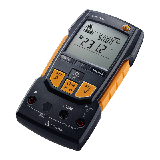
- Page 1 760 · Digital multimeter Instruction manual...
-
Page 2: Table Of Contents
7.4. Measuring resistance, capacitance, continuity and diode test ........16 7.4.1. testo 760-1 ............16 7.4.2. testo 760-2/-3 ............16 7.5. Frequency measurement (testo 760-1) ..17 7.6. Frequency measurement/duty cycle (testo 760-2/-3) ............. 17 7.7. Temperature measurement (optional) (testo 760-2/-3) ............. 17... - Page 3 9 Technical data ............20 9.1. General technical data ........20 9.2. More technical data ........21 9.2.1. testo 760-1 overload protection (10 A fuse) ..21 9.2.2. testo 760-2/-3 Overload protection (10 A fuse) ..22 10 Tips and assistance ..........24 10.1.
-
Page 4: Observe Prior To Use
• The measuring instrument may only be used in 16 A fused electrical circuits up to a nominal voltage of 600 V (testo 760-1 and -2) / 1000 V (testo 760-3). The nominal cross-section of the connection cable must be taken into account in order to ensure safe connection (e.g. via crocodile clips). -
Page 5: Intended Use
The instrument may only be used under the conditions and for the purpose for which it was designed: • testo 760-1 conforms to measurement category CAT III with a rated voltage of 600 V to earth. Measurement category CAT III is for use in electrical circuits in building installation, e.g. -
Page 6: Overview
On the rear: battery compartment and bracket for the probe tips On the rear: stand Input jack • testo 760-1: voltage, resistance, continuity, diode, capacitance and frequency measurements • testo 760-2/-3: voltage, resistance, continuity, diode, capacitance, frequency, duty cycle and temperature measurements Ground/COM jack for all measurements Input jack for AC and DC mA/µA current measurement (up to 600 mA) -
Page 7: Lc Display
Battery capacity 15 - 2% Battery capacity 2 – 0%, instrument switches off automatically flashes and acoustic signal emitted 10 Automatic power-off function is activated 11 Measuring units 12 Analog display (testo 760-2/-3 only) 13 Indication of polarity in bar chart (testo 760-2/-3 only) -
Page 8: Control Key Functions
RCDC measuring mode. Activates manual mode, Back to AUTO mode switch between AC and DC measuring mode and Current between mA and µA ranges (testo 760-2/-3 only). testo 760-1 Switch between resistance, capacitance, diode and continuity RCDC control testo 760-2/-3... -
Page 9: Further Functions
This function is available in all measuring modes. LPF (low-pass filter) function (testo 760-2/3) The LPF function activates the low-pass filter (1 kHz). The low-pass filter can be activated during the AC voltage measurement mode and also during AC current measurement mode. -
Page 10: Operating The Instrument
You can use the magnetic suspension system, which is available as an accessory, order number 0590 0001, to attach the testo 760 to metal surfaces. The suspension system’s magnet must not come anywhere near the battery compartment during the measurement (see graphic). -
Page 11: Switching The Instrument On
6 Operating the instrument WARNING Magnetic field May be harmful to those with pacemakers. > Keep a minimum distance of 15 cm between pacemaker and instrument. CAUTION Magnetic field Damage to other devices! > Keep a safe distance away from products that could be damaged by the effects of magnetism (e.g. -
Page 12: Carrying Out A Measurement
(COM) to the test object first of all. When disconnecting the test leads, always disconnect the test lead from the 10 A, V or mA jack (testo 760-2/-3) first of all. Installing the probe tip protector The probe tip protector can be removed/installed as required. -
Page 13: Current Measurement
The instrument is in automatic measuring mode when AUTO appears on the LC display. 7.3. Current measurement 7.3.1. testo 760-1 WARNING Serious risk of injury to the user and/or destruction of the instrument while measuring current. > Measuring circuit must be de-energized. -
Page 14: Testo 760-2/-3
The measuring instrument may only be used in 16 A fused electrical circuits up to a nominal voltage of 600 V (760-2) / 1000 V (760-3). The nominal cross-section of the connection cable must be taken into account in order to ensure safe connection (e.g. via crocodile clips). -
Page 15: Clamp Meter Adapter (0590 0003) Option (Testo 760-2/-3)
In this section, it is assumed that you are familiar with the contents of the documentation relating to the clamp meter adapter. Measuring direct currents (DC) Connect the testo 760 and clamp meter adapter to the test leads: black test lead to the jack; red test lead to the V/Ω/diode/capacitance... -
Page 16: Measuring Resistance, Capacitance, Continuity And Diode Test
You can use the magnetic suspension system, which is available as an accessory, order number 0590 0001, to attach the testo 760 to metal surfaces. The suspension system’s magnet must not come anywhere near the battery compartment during the measurement (see graphic). -
Page 17: Frequency Measurement (Testo 760-1)
Connect test leads to the test object. The instrument detects resistance, continuity, diode and capacitance, and automatically adjusts the measuring range. The measured value is shown on the LC display. Manual measuring mode (testo 760-2/-3) Disable AUTO RCDC measuring mode: press <1 s. -
Page 18: Service And Maintenance
8 Service and maintenance Connect the thermocouple adapter to the instrument: Insert the adapter into the jack and into the V/Ω/diode/capacitance. jack. Ensure correct polarity! The thermocouple adapter switches on automatically. The instrument is in AUTO V mode. Activate AUTO RCDC measuring mode for temperature measurements: press >2 s. -
Page 19: Changing The Fuses
If a malfunction occurs during operation, the ongoing measurement should be stopped immediately. Send the instrument to Testo Service for checking. 8.5. Calibration In order to maintain the specified accuracy of the measurement results, Testo recommends calibrating the instrument once a year. -
Page 20: Technical Data
-15 °C to +60°C Humidity 0 to 80% RH Operating altitude Up to 2000 m Measurement category testo 760-1: CAT III / 600 V testo 760-2: CAT IV/600 V testo 760-3: CAT IV/600 V Level of contamination 2 Protection class... -
Page 21: More Technical Data
9 Technical data 9.2. More technical data 9.2.1. testo 760-1 overload protection (10 A fuse) Feature Measuring range Resolution Accuracy DC voltage 400 mV 0.1 mV ± (0.8% of meas. val. 4.000 V 1 mV + 3 digits) 40.00 V 10 mV 400.0 V... -
Page 22: Testo 760-2/-3 Overload Protection (10 A Fuse)
9.999 kHz 1 Hz Figures correspond to +23 °C ± 5 °C at <80% rel. humidity. Temperature coefficient: 0.15 x specified accuracy per 1 °C (<18 °C and >28 °C) 9.2.2. testo 760-2/-3 Overload protection (10 A fuse) Feature Measuring... - Page 23 9 Technical data Feature Measuring Resolution Accuracy range DC current 600 μA 0.1 μA ± (1.5% of meas. val. 6000 μA 1 μA + 5 digits) 60.00 mA 10 μA 600.0 mA 100 μA 1 mA 10 A 10 mA AC current 600 μA 0.1 μA...
-
Page 24: Tips And Assistance
10 Tips and assistance Feature Measuring Resolution Accuracy range 600.0 Hz Frequency 0.1 Hz ± (0.1% + 1 digits) 6.000 kHz measurement 1 Hz 60.00 kHz 10 Hz 600.0 kHz 100 Hz 6.000 MHz 1 kHz 60.00 MHz 10 kHz 99.99 Hz Frequency with 0.01 Hz... -
Page 25: Accessories And Spare Parts
Defective fuse If a fuse for the (testo 760-1, and/or indication (testo 760-2/-3) jack is defective, the instrument will no longer detect the corresponding jack. Instrument will not switch to A-mode. > Replace defective fuse. If we have not been able to answer your question, please contact your dealer or Testo Customer Service. - Page 26 0970 7600 en 03...
Need help?
Do you have a question about the 760 and is the answer not in the manual?
Questions and answers