Amit VHG760AM-0T001 User Manual
In-vehicle hotspot gateway
Hide thumbs
Also See for VHG760AM-0T001:
- User manual (408 pages) ,
- User manual (359 pages) ,
- Quick installation manual (19 pages)
Table of Contents
Advertisement
Advertisement
Table of Contents

Subscribe to Our Youtube Channel
Related Manuals for Amit VHG760AM-0T001


Summary of Contents for Amit VHG760AM-0T001
-
Page 1: User Manual
User Manual VHG760AM-0T001 In-Vehicle Hotspot Gateway UM: V1.0 20160201... -
Page 2: Table Of Contents
......................... 24 IREWALL TATUS 3.4.1 Packet Filters ..........................25 3.4.2 URL Blocking ..........................25 3.4.3 Web Content Filters ........................25 3.4.4 MAC Control ..........................25 II VHG760AM-0T001 User Manual... - Page 3 4.2.2 VLAN ............................. 59 4.2.2.1 VLAN Scenarios ............................... 60 4.2.2.2 Port-Based VLAN ............................. 63 4.2.2.3 Tag-Based VLAN .............................. 65 ........................... 67 ETUP 4.3.1 Configuration ..........................67 III VHG760AM-0T001 User Manual...
- Page 4 5.1.3 URL Blocking ..........................111 5.1.3.1 Configuration ..............................112 5.1.3.2 URL Blocking Rule List ..........................112 5.1.3.3 URL Blocking Rule Configuration ........................112 5.1.4 Web Content Filters ........................113 IV VHG760AM-0T001 User Manual...
- Page 5 5.3.3 PPTP ............................140 5.3.3.1 PPTP / L2TP VPN Tunnel Scenarios ....................... 140 5.3.3.2 Configuration ..............................141 5.3.3.3 PPTP Server Configuration ..........................141 5.3.3.4 PPTP Server Status ............................142 V VHG760AM-0T001 User Manual...
- Page 6 5.6.2.1 Trusted CA Certificate List ..........................160 5.6.2.2 Trusted Client Certificate List ......................... 160 5.6.3 Issue Certificates ........................161 CHAPTER 6 APPLICATIONS ..........................163 ......................... 163 OBILE PPLICATIONS 6.1.1 SMS ............................164 VI VHG760AM-0T001 User Manual...
- Page 7 7.2.1.1 Time Schedule List ............................186 ........................... 186 ROUPING 7.3.1 Configuration ..........................187 7.3.2 Host Grouping ..........................187 7.3.2.1 Host Group List ............................... 187 7.3.2.2 Host Group Configuration ..........................188 VII VHG760AM-0T001 User Manual...
- Page 8 7.3.4.2 L7 Application Group Configuration ....................... 190 ........................191 XTERNAL ERVERS 7.4.1 Add External Servers ........................191 MMI ............................192 7.5.1 Web UI ........................... 192 VIII VHG760AM-0T001 User Manual...
- Page 9 Trademarks All products, company, brand names are trademarks or registered trademarks of their respective companies. They are used for identification purpose only. Specifications are subject to be changed without prior notice. IX VHG760AM-0T001 User Manual...
-
Page 10: Chapter 1 Introduction
InVehicle Hotspot Gateway Chapter 1 Introduction Congratulations on your purchase of this outstanding product: In‐Vehicle Hotspot Gateway. For M2M (Machine‐to‐Machine) applications, AMIT In‐Vehicle Hotspot Gateway is absolutely the right choice. With built‐in world‐class 3G HSPA+ module, you just need to insert SIM card from local mobile carrier to get to Internet. The redundant SIM design provides a more reliable WAN connection for critical applications. By VPN tunneling technology, remote sites easily become a part of Intranet, and all data are transmitted in a secure (256‐bit AES encryption) link. To meet a variety of M2M application requirements, AMIT In‐Vehicle Hotspot Gateway products are based on modular design. A new functional module can replace current one to support new application in short time, such as for NFC or GPS applications. This VHG760AM‐0T001 product is loaded with luxuriant security features including VPN, firewall, NAT, port forwarding, DHCP server and many other powerful features for complex and demanding business and M2M (Machine‐to‐Machine) applications. The redundancy design in fallback 9‐36 VDC power terminal, dual SIM cards and VRRP function makes the device as a back‐up in power, network connection and data transmission without lost. Main Features: Provide various and configurable WAN connection. ... -
Page 11: Content List
InVehicle Hotspot Gateway Content List Table‐1.1 Contents included in your package Items Description Contents Quantity VHG760AM-0T001 1pcs In-Vehicle Hotspot Gateway Cellular Antenna 2pcs 2pcs WiFi Antenna 1pcs (Manual) Mounting Bracket 2pcs 2 VHG760AM-0T001 User Manual... -
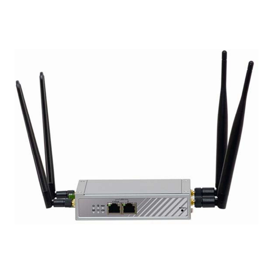
Page 12: Overview
The RESET button provides user with a quick and easy way to resort the default setting. Press the RESET button continuously for 6 seconds, and then release it. The device will restore to factory default settings. SIM Slot Figure 1‐2 Outward appearance of the VHG760 bottom side 3 VHG760AM-0T001 User Manual... -
Page 13: Pre-Installation Requirements
Windows®, Macintosh, or Linux-based operating system Web-based Configuration Utility An installed Ethernet adapter Requirements Browser Requirements: Internet Explorer 6.0 or higher Chrome 2.0 or higher Firefox 3.0 or higher 4 VHG760AM-0T001 User Manual... -
Page 14: Led Indication
Steady ON: SIM card is chosen for Green connection High Cellular Steady ON: The signal strength of Cellular Green Signal is strong Low Cellular Steady ON: The signal strength of Cellular Green Signal is weak 5 VHG760AM-0T001 User Manual... -
Page 16: Chapter 2 Getting Start
The VHG760AM‐0T001 can be placed on a desktop, mounted on the wall or mounted on a DIN‐rail. The DIN‐rail bracket is not screwed on the product when out of factory. Please screw the DIN‐rail bracket on the product first if necessary. Step 1: Step 2: Step 3: Follow red arrow to Lift up SIM holder, Put back SIM holder, unlock the SIM card and insert SIM card and follow red arrow slot to lock SIM socket Figure 2‐1 The SIM card installation instructions 7 VHG760AM-0T001 User Manual ... -
Page 17: Connecting Power
Note that each package includes a DC converter and a DC12V/2A power adapter1 for you to easily connect DC power adapter to this terminal block. Figure 2‐3 The DC converter and DC 12V/2A power adapter 2.1.4 Connect to a Host for Configuration The VHG760 series provides two 10/100Mbps Ethernet RJ‐45 ports. The RJ‐45 ports are capable of auto‐detecting the transmission speed of the Ethernet and performing self‐configuration. Plug one RJ‐45 connector of an Ethernet cable into your computer’s RJ‐45 port and then plug the alternate into one of the two RJ‐45 ports on the front panel of the unit. Note that you need to 1 The maximum power consumption of VHG760AM‐0T001 is 15.5W. 8 VHG760AM-0T001 User Manual... -
Page 18: Easy Setup By Configuring Web Ui
URL into a chosen browser. The default URL is http://192.168.123.254/. Figure 2‐4 Input the default URL for Web‐based UI access. Following the above step is a login web page prompting for user authentication to login the Web‐based UI. Please input your login password into the blank next to the “Password”. Refer to Figure‐2.5 for reference. Note that the default password is “admin”. Figure 2‐5 Login page for user authentication 9 VHG760AM-0T001 User Manual... -
Page 19: Wizard
You can browse web user interface (UI) to configure the device. First you need to launch the Setup Wizard browser and then the Setup Wizard will guide you step‐by‐step to finish the setup process. After login, select your language from the list. Figure 2‐6 Choose your language Wizard Select “Wizard” for basic network settings and VPN settings in a simple way. Or, you can go to Basic Network / Advanced Network / Applications / System to setup the configuration by your own selection. Figure 2‐7 Get start with wizard 2.3.1 Configure with the Network Setup Wizard 10 VHG760AM-0T001 User Manual... - Page 20 Confirmation” item. Otherwise, keep each item blank for reserving the current password. Note that, change the default password is strongly recommended. Press “Next” to continue. Step 3: Time Zone Time Zone Configuration: The VHG760 unit detects your time zone automatically. For fixing the detection if needed, you can either click the “Detect Again” button or select a time zone manually. Press “Next” to continue. 11 VHG760AM-0T001 User Manual...
- Page 21 ISP (Internet Service Provider) manually. This option is usually chosen when you get a fixed IP address from ISP. About how to obtain appropriate static IP configuration, please contact with your network administrator or ISPs. Press “Next” to continue. Step 4-3: Ethernet - PPP over Ethernet) 12 VHG760AM-0T001 User Manual...
- Page 22 SIM card, you can select “Auto‐Detection” to finish dial‐up profile automatically. This option is chosen when you want to connect to Internet through 3G/4G networks rather than fixed line broadband access network technologies mentioned above. 13 VHG760AM-0T001 User Manual...
- Page 23 65 seconds to restart this gateway and take new settings effective. Step 8: Counting Down Configuration is completed. Press “Finish” button to close Setup Wizard and browser counts down for 65 seconds and provides you with “Click here” button to reconnect to the device. 14 VHG760AM-0T001 User Manual...
-
Page 24: Configure With The Vpn Setup Wizard
“Select VPN Type”, “VPN Configuration”, “Setup Summary & Apply”, and “Configuration Complete” in order. Note that If you do not need to construct a VPN, you can skip this wizard setting. Press “Next” to start the wizard. Step 2: VPN Type Select type of VPN connection you want to create. Here you can choose IPSec, PPTP, L2TP, or GRE. (Refer to Session 3.2.3 for more details.) Press “Next” to continue. 15 VHG760AM-0T001 User Manual... - Page 25 If choosing PPTP Server, please select options of authentication and MPPE. You also need to create a set of username and password for PPTP clients. In this wizard, you can only create one user account. If you want to create more user accounts, please go to Advanced Network‐>VPN‐> PPTP to add more users. 16 VHG760AM-0T001 User Manual...
- Page 26 L2TP clients. In this wizard, you can only create one user account. If you want to create more user accounts, please go to Advanced Network‐>VPN‐> L2TP to add more users. Press “Next” to continue. Step 4: Confirm and Apply Confirm new settings. If all new settings are correct, please press “Apply” button to save these new settings and take them effective. 17 VHG760AM-0T001 User Manual...
-
Page 28: Chapter 3 Status Information
InVehicle Hotspot Gateway Chapter 3 Status Information There are 6 kinds of system status to be shown at this window. They are Network Status, WiFi Status, LAN Client List, Firewall Status, VPN Status and System Management Status. Figure 3‐1 Choose the “Status” feature Network Status In Network Status page, you can review lots information of network status, including a connection diagram, WAN IPv4 status, WAN IPv6 status, LAN status, and 3G/4G modem status. You can also check the device time at the bottom of this page. Figure 3‐2 Sub‐feature: Network Status 19 VHG760AM-0T001 User Manual ... -
Page 29: Network Connectivity Diagram
4. WiFi Client Icon: Indicates how many WiFi clients are connected now. 3.1.2 WAN Interface IPv4 Network Status Display WAN type, IPv4 information, MAC information, and connection status of multiple WAN interfaces in IPv4 networking. Press “Edit” button if you want to change settings. Figure 3‐4 WAN status: IPv4 connectivity 3.1.3 WAN Interface IPv6 Network Status Display WAN type, IPv6 information, and connection status of multiple WAN interfaces in IPv6 networking. Press “Edit” button if you want to change settings. Figure 3‐5 WAN status: IPv6 connectivity 20 VHG760AM-0T001 User Manual... -
Page 30: Lan Interface Status
Display IPv4 and IPv6 information of local network. Press “Edit” button if you want to change settings. Figure 3‐6 LAN status: IPv4/IPv6 connectivity 3.1.5 3G/4G Modem Status Display modem information, link status, signal strength, and network (carrier) name of 3G/4G connection. Figure 3‐7 3G/4G status ‐ mobile network connectivity 3.1.6 Internet Traffic Statistics Display number of transmitted packets and received packets of each WAN interface. Figure 3‐8 Internet traffic statistics 21 VHG760AM-0T001 User Manual... -
Page 31: Wifi Status
3.2.1 WiFi Virtual AP List In order to view the basic information of WiFi virtual APs, it will display operation band, virtual AP ID, WiFi activity, operation mode, SSID, channel, WiFi system, WiFi security approach and MAC address of all virtual APs on status page. Besides, there is an additional Edit command button for each virtual AP to link to the configuration page of that dedicated virtual AP. Figure 3‐10 WiFi virtual AP list 22 VHG760AM-0T001 User Manual... -
Page 32: Wifi Traffic Statistics
InVehicle Hotspot Gateway 3.2.2 WiFi Traffic Statistics In order to view the traffic statistics of WiFi virtual APs, it will display operation band, virtual AP ID and the numbers of received packets and transmitted packets of all virtual APs on status page. Besides, there is an additional Reset command button for each virtual AP to clear the traffic statistics. Figure 3‐11 WiFi traffic statistics LAN Client List Figure 3‐12 Sub‐feature: LAN client list 23 VHG760AM-0T001 User Manual... -
Page 33: Firewall Status
IP address configuration, host name, MAC address and remaining lease time of all client devices on status page. Figure 3‐13 LAN client list Firewall Status In Firewall Status page, you can review lots information of filter status, including Packet Filters, URL Blocking, Web Content Filters, MAC Control, Application Filters, IPS and other options of firewall. Figure 3‐14 Sub‐feature: firewall status 24 VHG760AM-0T001 User Manual... -
Page 34: Packet Filters
InVehicle Hotspot Gateway 3.4.1 Packet Filters Display all detected contents of firing activated packet filter rules. Figure 3‐15 Packet filters 3.4.2 URL Blocking Display all blocked URLs of firing activated URL blocking rules. Figure 3‐16 URL blocking 3.4.3 Web Content Filters Display all detected contents of firing activated Web content filter rules. Figure 3‐17 Web content filters 3.4.4 MAC Control Display all blocked MAC addresses of firing activated MAC control rules. Figure 3‐18 MAC control 3.4.5 Application Filters Display all activated rules of application filters 25 VHG760AM-0T001 User Manual... -
Page 35: Ips
InVehicle Hotspot Gateway Figure 3‐19 Application filters 3.4.6 IPS Display all events of firing activated rules of IPS. Figure 3‐20 IPS 3.4.7 Options Display option settings of firewall. Figure 3‐21 Options VPN Status In VPN Status page, you can review lots information of VPN status, including IPSec status, PPTP Server status, PPTP Client status, L2TP Server status and L2TP Client status. Figure 3‐22 Sub‐feature: VPN status 26 VHG760AM-0T001 User Manual... -
Page 36: Ipsec Status
InVehicle Hotspot Gateway 3.5.1 IPSec Status Display the status of all activated tunnels of IPSec. Figure 3‐23 IPSec status 3.5.2 PPTP Server Status Display the status of all activated accounts of PPTP server. Figure 3‐24 PPTP server status 3.5.3 PPTP Client Status Display the status of all activated PPTP clients. Figure 3‐25 PPTP client status 3.5.4 L2TP Server Status Display the status of all activated accounts of L2TP server. Figure 3‐26 L2TP server status 3.5.5 L2TP Client Status Display the status of all activated L2TP clients. 27 VHG760AM-0T001 User Manual... -
Page 37: System Management Status
InVehicle Hotspot Gateway Figure 3‐27 L2TP client status System Management Status In System Management Status page, you can review lots information of SNMP and TR‐069 status. Figure 3‐28 Sub‐feature: system management status 3.6.1 SNMP Linking Status Display information of SNMP linking. Figure-3.29 SNMP linking status 3.6.2 SNMP Trap Information Display information of SNMP traps. 28 VHG760AM-0T001 User Manual... -
Page 38: Status
InVehicle Hotspot Gateway Figure 3‐29 SNMP trap information 3.6.3 TR-069 Status Display link status of TR‐069. Figure 3‐30 TR‐069 status 3.6.4 UPnP Status Figure 3‐31 UPnP status 29 VHG760AM-0T001 User Manual... -
Page 40: Chapter 4 Basic Network Configuration
Please refer to Session 2.2 for knowing how to login into the Web‐based UI. You can select to configure “Basic Network” features from the left‐hand side manual buttons of web pages after you login into the web‐based UI. The “Basic Network” button is marked with golden background color in Figure‐4.1. Figure 4‐1 Choose the “Basic Network” feature 31 VHG760AM-0T001 User Manual ... -
Page 41: Wan Setup
SIM card is inserted / removed into / from the powered-on IDG-766 unit. Please follow instructions at section 2.1.1 to insert / remove a SIM card. 2 The specification of embedded module depends on respective model. 32 VHG760AM-0T001 User Manual... -
Page 42: Physical Interface
Figure 4‐4 Physical interface list Click on the “Edit” button for each WAN interface and you can get the detail physical interface settings and then configure the settings as well. By default, the WAN‐1 interface is forced to “Always on” mode, and operates as the primary internet connection; the interfaces WAN‐2 is disabled. 33 VHG760AM-0T001 User Manual... -
Page 43: Internet Configuration
Always on: Set this WAN interface to be active all the time. It means two or more Internet connections will be established simultaneously, and outgoing data will be transferred through these WAN connections base on load balance policies. This mode is especially suitable for high bandwidth requirement, such as video stream transmission. 34 VHG760AM-0T001 User Manual... - Page 44 Line Speed: You can specify the upstream / downstream speed (Mbps) for the corresponding WAN connection. Such information will be referred in QoS and load balance function to manage the traffic load for each WAN connection. VLAN Tagging: If your ISP required a VLAN tag to be inserted into the WAN packets, you can enable this setting, and enter the specified tag value. Afterwards, click on “Save” to store your settings or click “Undo” to give up the changes. 3 Please note your ISP will charge the connection fee even if it’s set to seamless failover. 35 VHG760AM-0T001 User Manual...
-
Page 45: Internet Setup
Internet connection setup. They include the 3G/4G and Ethernet WAN types. For 3G/4G WAN type, the WAN interface is 3G/4G and the ISP is a mobile operator that can provide LTE, HSPA+, HSPA, WCDMA, EDGE, GPRS data services4. However, for Ethernet WAN interface, a fixed line ISP provides xDSL or cable modem with Dynamic IP, Static IP, PPPoE, PPTP and L2TP connection types. 4 Different models have different specifications of embedded 3G module. Please refer to specification file for details. 36 VHG760AM-0T001 User Manual... - Page 46 Connection Control mode to Connect‐on‐demand or Manually. Dynamic IP Address: You may choose this WAN type if you connects a cable modem or a fiber (VDSL modem) for Internet connection. The assigned IP address may be different every time. Static IP Address: If you get a fixed IP address from your ISP. 37 VHG760AM-0T001 User Manual...
-
Page 47: Internet Connection List
4.1.2.3 Ethernet WAN Click on the “Edit” button for the Ethernet WAN interface and you can get the detail WAN settings and then configure the settings as well. The device provides “Static IP Address”, “Dynamic IP Address”, “PPP over Ethernet”, “PPTP” and “L2TP” WAN types for the Ethernet WAN interface to connect to the Internet. 38 VHG760AM-0T001 User Manual... - Page 48 InVehicle Hotspot Gateway Figure 4‐13 Edit WAN interface: ethernet type 4.1.2.3.1 Dynamic IP Address Figure 4‐14 Choose WAN type: Dynamic IP Figure 4‐15 Dynamic IP configuration 39 VHG760AM-0T001 User Manual...
- Page 49 Check Interval: Indicate how often to send keep‐alive packet. Check Timeout: Set allowance of time period to receive response of keep‐alive packet. If this gateway doesn’t receive response within this time period, this gateway will record this keep alive is failed. Latency Threshold: Set acceptance of response time. This gateway will record this keep‐alive check is failed if the response time of replied packet is longer than this setting. Fail Threshold: Times of failed checking. This WAN connection will be recognized as broken if the 40 VHG760AM-0T001 User Manual...
- Page 50 Target1/Target2: Set host that is used for keep alive checking. It can be DNS1, DNS2, default Gateway, or other host that you need to input IP address manually. IGMP: Enable or disable multicast traffics from Internet. You may enable as auto mode or select by IGMP v1, IGMP v2, IGMP v3 or Auto. WAN IP Alias: In some cases, ISP will provide you another fixed IP address for management purpose. You can enter that IP address in this field. 4.1.2.3.2 Static IP Address Select this option if ISP provides a fixed IP address to you. You will need to enter in the IP address, subnet mask, and gateway address, provided to you by your ISP. Each IP address entered in the fields must be in the appropriate IP form, which is four IP octets separated by a dot (x.x.x.x). The gateway will not accept the IP address if the format is not correct. Figure 4‐16 Choose WAN type: static IP 41 VHG760AM-0T001 User Manual...
- Page 51 WAN IP address/ Subnet Mask/ Gateway: Enter the IP address, subnet mask, and gateway address which is provided by your ISP. Primary DNS/ Secondary DNS: Input the IP address of primary and secondary DNS server that is provided by your ISP. Secondary DNS can be ignored if only one DNS server is provided by your ISP. MTU: Most ISP offers MTU value to users. The default value is 0 (auto). NAT: By default, it is enabled. If you disable this option, there will be no NAT mechanism between LAN side and WAN side. Network Monitoring: You can do preferred settings by using this feature to monitor the connection status of WAN interface. Checking mechanism depends on several parameters 42 VHG760AM-0T001 User Manual...
- Page 52 Target1/Target2: Set host that is used for keep alive checking. It can be DNS1, DNS2, default Gateway, or other host that you need to input IP address manually. IGMP: Enable or disable multicast traffics from Internet. You may enable as auto mode or select by IGMP v1, IGMP v2, IGMP v3 or Auto. WAN IP Alias: In some cases, ISP will provide you another fixed IP address for management purpose. You can enter that IP address in this field. 4.1.2.3.3 PPP over Ethernet Select this option if your ISP requires you to use a PPPoE connection. This option is typically used for ADSL services. 43 VHG760AM-0T001 User Manual...
- Page 53 InVehicle Hotspot Gateway Figure 4‐18 Choose WAN type: PPPoE Figure 4‐19 PPPoE configuration 44 VHG760AM-0T001 User Manual...
- Page 54 WAN interface. Checking mechanism depends on several parameters defined here. The network monitoring provides the WAN interface status and then system can prevent embedded 3G/LTE modem from some sort of auto‐timeout and disconnects from the Internet after a period of inactivity. Enable: Check the box to do Network Monitoring. DNS Query/ICMP Checking: Do the keep alive through DNS query packets or ICMP packets. Loading Checking: The response time of replied keep‐alive packets may increase when WAN bandwidth is fully occupied. To avoid keep‐alive feature work abnormally, enable this option will stop sending keep‐alive packets when there are continuous incoming and outgoing data packets 45 VHG760AM-0T001 User Manual...
- Page 55 Target1/Target2: Set host that is used for keep alive checking. It can be DNS1, DNS2, default Gateway, or other host that you need to input IP address manually.. IGMP: Enable or disable multicast traffics from Internet. You may enable as auto mode or select by IGMP v1, IGMP v2, IGMP v3 or Auto. WAN IP Alias: In some cases, ISP will provide you another fixed IP address for management purpose. You can enter that IP address in this field. 4.1.2.3.4 PPTP Choose PPTP (Point‐to‐Point Tunneling Protocol) if your ISP used a PPTP connection. Your ISP will provide you with a username and password. Figure 4‐20 Choose WAN type: PPTP 46 VHG760AM-0T001 User Manual...
- Page 56 IP Address” accordingly. If you select “Static IP Address” option, you have to specify additional “WAN IP Address”, “WAN Subnet Mask”, and “WAN Gateway” settings provided by your ISP. Figure 4‐22 IP mode configuration Server IP Address/ Name: IP address of the PPTP server provided by ISP. PPTP Account and Password: The account and password your ISP assigned to you. Please note the account and password is case sensitive. For security concern, the password you input won’t be displayed on web UI. Connection ID: Optional, input the connection ID if your ISP requires it. Connection Control: Select your connection control scheme from the drop list: “Auto‐reconnect 47 VHG760AM-0T001 User Manual...
- Page 57 Latency Threshold: Set acceptance of response time. This gateway will record this keep‐alive check is failed if the response time of replied packet is longer than this setting. Fail Threshold: Times of failed checking. This WAN connection will be recognized as broken if the times of continuous failed keep‐alive checking equals to this value. Target1/Target2: Set host that is used for keep alive checking. It can be DNS1, DNS2, default Gateway, or other host that you need to input IP address manually. IGMP: Enable or disable multicast traffics from Internet. You may enable as auto mode or select 48 VHG760AM-0T001 User Manual...
- Page 58 InVehicle Hotspot Gateway by IGMP v1, IGMP v2, IGMP v3 or Auto. WAN IP Alias: In some cases, ISP will provide you another fixed IP address for management purpose. You can enter that IP address in this field. 4.1.2.3.5 L2TP Choose L2TP (Layer 2 Tunneling Protocol) if your ISP used a L2TP connection. Your ISP will provide you with a username and password. Figure 4‐23 Choose WAN type: L2TP Figure 4‐24 L2TP configuration 49 VHG760AM-0T001 User Manual...
- Page 59 Network Monitoring: You can do preferred settings by using this feature to monitor the connection status of WAN interface. Checking mechanism depends on several parameters defined here. The network monitoring provides the WAN interface status and then system can prevent embedded 3G/LTE modem from some sort of auto‐timeout and disconnects from the 50 VHG760AM-0T001 User Manual...
-
Page 60: 4G Wan
Target1/Target2: Set host that is used for keep alive checking. It can be DNS1, DNS2, default Gateway, or other host that you need to input IP address manually. IGMP: Enable or disable multicast traffics from Internet. You may enable as auto mode or select by IGMP v1, IGMP v2, IGMP v3 or Auto. WAN IP Alias: In some cases, ISP will provide you another fixed IP address for management purpose. You can enter that IP address in this field. 4.1.2.4 3G/4G WAN Figure 4‐26 Edit mobile WAN connection 4.1.2.4.1 3G/4G WAN Type Configuration 51 VHG760AM-0T001 User Manual... - Page 61 APN, dialed number, account or password. If you know this information exactly, you can choose “Manual‐configuration” option and type in that information by your own. Otherwise, you can select “Auto‐detection” to let this gateway 52 VHG760AM-0T001 User Manual...
- Page 62 Time Schedule: This option allows you to limit WAN connection available in a certain time period. You can select “Always” available or “By Schedule” for connection method. If you choose “By Schedule” rule, you need to add a new schedule at System ‐> Scheduling menu. MTU: MTU refers to Maximum Transmit Unit. Different WAN types of connection will have different value. You can leave it with 0 (Auto) if you are not sure about this setting. 53 VHG760AM-0T001 User Manual...
-
Page 63: Load Balance
This device support multi‐WAN load balance function and more than one WAN interface can access to Internet at a time. The load balance function can help you to manage the outbound traffics and to maximize the utilization of available bandwidth. 4.1.3.1 Configuration 54 VHG760AM-0T001 User Manual... -
Page 64: By Smart Weight
InVehicle Hotspot Gateway Figure 4‐30 Enabling load balance Load Balance: Enable or disable the load balance function. Load Balance Strategy: Once you enabled the load balance function, you have to further configure which strategy is to be applied for load balancing the outbound traffics. There are three load balance strategy: “By Smart Weight”, “By Priority”, and “By User Policy”. 4.1.3.2 By Smart Weight Figure 4‐31 Choose load balance strategy: by smart weight If you choose the “By Smart Weight” strategy, no any other setting is required. This device will automatically allocate the outbound traffics to each WAN interface. 4.1.3.3 By Priority Figure 4‐32 Choose load balance strategy: by priority 55 VHG760AM-0T001 User Manual... -
Page 65: By User Policy
InVehicle Hotspot Gateway If you choose the “By Priority” strategy, you have to further specify the outbound traffic percentage for each WAN interface. The load balancing mechanism will follow these settings to allocate proper connection traffics for each WAN to access the internet. 4.1.3.4 By User Policy Figure 4‐33 Choose load balance strategy: by priority If you choose the “By User Policy” strategy, you have to create the expected policies one by one. Click the “add” button to add your load balance policy. Figure 4‐34 User policy list You can manage the outbound traffic flows and force specific traffics to access Internet through designated WAN interface. For those traffics not covered in the user policy rules, the device will allocate the WAN interface by applying “Smart Weight” mechanism simultaneously. Figure 4‐35 Edit user policies 56 VHG760AM-0T001 User Manual... - Page 66 “Any”, “Subnet”, “IP Range”, or “Single IP”. Just choose one type of the source IP address, and specify its value as well. If you don’t want to specify a certain source IP address for this policy, just leave it as “Any”. Destination IP Address: Enter the expected Destination IP Address for the load balance policy. It can be “Any”, “Subnet”, “IP Range”, “Single IP”, or “Domain Name”. Just choose one type of the destination IP address, and specify its value as well. If you don’t want to specify a certain destination IP address for this policy, just leave it as “Any”. Destination Port: Enter the expected Destination Port number for the load balance policy. It can be “All”, “Port Range”, “Single Port”, or “Well‐known Applications”. Just choose one type of the destination port, and specify its value as well. If you don’t want to specify a certain destination port for this policy, just leave it as “All”. Protocol: Enter the expected protocol type for the load balance policy. It can be “TCP”, “UDP” or “Both”. If you don’t want to specify a certain protocol type for this policy, just leave it as “Both”. WAN Interface: Identify which WAN interface is to be selected for accessing the Internet if all of above source and destination criteria are matched for the outbound traffics. Policy: Enable or disable this user policy. 57 VHG760AM-0T001 User Manual...
-
Page 67: Lan & Vlan Setup
Ethernet WAN interface for Internet connection. Please see the Basic Network >> WAN settings. Besides, VLAN function is provided to organize your local networks. Figure 4‐36 Sub‐feature: LAN&VLAN 4.2.1 Ethernet LAN 4.2.1.1 Configuration Please follow the following instructions to do IPv4 Ethernet LAN Setup. Figure 4‐37 Ethernet LAN configuration LAN IP Address: The local IP address of this device. The computer on your network must use the LAN IP address of this device as their Default Gateway. You can change it if necessary. It’s also the 5 The 1 Ethernet port will be configured to WAN port if you have set Ethernet WAN. 58 VHG760AM-0T001 User Manual... -
Page 68: Vlan
Port‐based VLAN and Tag‐based VLAN. In Port‐based VLAN, all client hosts belong to the same group by transferring data via some physical ports that are tagged with same VLAN ID in the device. The ports of a VLAN form an independent traffic domain in which the traffic generated by the nodes remains within the VLAN. However, in Tag‐based VLAN, all packets with same VLAN ID will be treated as the same group of them and own same access property and QoS property. It is especially useful when individuals of a VLAN group are located at different location. The VLAN function allows you to divide local network into different “virtual LANs”. In some cases, ISP may need router to support “VLAN tag” for certain kinds of services (e.g. IPTV) to work 59 VHG760AM-0T001 User Manual... -
Page 69: Vlan Scenarios
Port‐4 and VAP‐8 (SSID: Guest) with NAT mode and DHCP‐3 server equipped. He also configure Lab & Servers segment with VLAN ID 3. The VLAN group includes Port‐3 with NAT mode and DHCP‐2 server equipped. However, he configure Office segment with VLAN ID 2. The VLAN group includes Port‐2 and VAP‐1 (SSID: Staff) with NAT mode and DHCP‐1 server equipped. At last, administrator also configure VoIP & IPTV segment with VLAN ID 11. The VLAN group includes Port‐1 with bridge mode to WAN interface as shown at following diagram. 60 VHG760AM-0T001 User Manual... - Page 70 Intranet. These flows can be directed to different destination because they have differentiated tags. The approach is very useful to group some hosts in different geographic location to be a same department. Figure 4‐41 Scenario of tag‐based VLAN Tag‐based VLAN is also called a VLAN Trunk. The VLAN Trunk collects all packet flows with 61 VHG760AM-0T001 User Manual...
- Page 71 That is, any client host in VLAN 11 group can’t access the Internet. However, he configure Office segment with VLAN ID 10. The VLAN group is equipped with DHCP‐1 server to construct a 192.168.10.x subnet. In this example, VLAN 10 and 12 groups can access the Internet as following diagram. Figure 4‐42 Network topology of IDG‐766 tag‐based VLAN VLAN Group Access Control Administrator can specify the Internet access right for all VLAN groups. He also can configure which VLAN groups can communicate each other. VLAN Group Internet Access Administrator can specify members of one VLAN group to be able to access Internet or not. Following is an example that VLAN groups of VID is 1 and 4 can access Internet but the one with VID is 3 can’t. That is, visitors in Lobby and staffs in office can access Internet. But ones in Lab can’t since security issue. Servers in Lab serve only for trusted staffs or are accessed in secure tunnels. 62 VHG760AM-0T001 User Manual...
-
Page 72: Port-Based Vlan
A port‐based VLAN is a group of ports on an Ethernet switch or router that form a logical Ethernet segment. There are four LAN ports and up to eight virtual APs in this device, so you can have various VLAN configurations to organization the available LAN ports and virtual APs if required. 63 VHG760AM-0T001 User Manual... - Page 73 By default, all the 4 LAN ports and 8 virtual APs belong to one VLAN, and this VLAN is a NAT type network, all the local device IP addresses are allocated by DHCP server 1. If you want to divide them into different VLANs, click on the “Edit” button related to each port. Type: Select “NAT” or “Bridge” to identify if the packets are directly bridged to the WAN port or processed by NAT mechanism. LAN VID: Specify a VLAN identifier for this port. The ports with the same VID are in the same VLAN group. Tx TAG: If ISP requests a “VLAN Tag” with your outgoing data, please check the checkbox of “Tx TAG”. DHCP Server: Specify a DHCP server for the configuring VLAN. This device provides up to 4 DHCP servers to serve the DHCP requests from different VLANs. WAN VID: The VLAN Tag ID that come from the ISP service. For NAT type VLAN, no WAN VLAN tag is allowed and the value is forced to “0”; For Bridge type VLAN, You have to specify the VLAN Tag value that is provided by your ISP. VLAN Routing Group: 64 VHG760AM-0T001 User Manual...
-
Page 74: Tag-Based Vlan
VLAN, where the port VIDs assigned to the ports determine VLAN membership. When the device receives a frame with a VLAN tag, referred to as a tagged frame, the device forwards the frame only to those ports that share the same VID. 65 VHG760AM-0T001 User Manual... - Page 75 1. VLAN ID: Specify a VLAN tag for this VLAN group. The ports with the same VID are in the same VLAN group. 2. Internet: Specify whether this VLAN group can access Internet or not. If it is checked, all the packet will be un‐tagged before it is forward to Internet, and all the packets from Internet will be tagged with the VLAN ID before it is forward to the destination belongs to this configuring VLAN group in the Intranet. 3. Port-1 ~ Port-4, VAP-1 ~ VAP-8: Specify whether they belong to the VLAN group or not. You just have to check the boxes for dedicated ports. 66 VHG760AM-0T001 User Manual...
-
Page 76: Wifi Setup
4. DHCP Server: Specify a DHCP server for the configuring VLAN. This device provides up to 4 DHCP servers to serve the DHCP requests from different VLANs. Afterwards, click on “Save” to store your settings or click “Undo” to give up the changes. WiFi Setup The gateway supports 2.4GHz 802.11n 2Tx2R MIMO WiFi, and also can be back compatible to 802.11b/g clients. WiFi settings allow you to set the wireless LAN configuration items. When the wireless configuration is done, your WiFi LAN is ready to support your local WiFi devices such as your laptop PC, smart phone, tablet, wireless printer and some portable wireless devices. Figure 4‐49 Sub‐feature: WiFi 4.3.1 Configuration This device is equipped with IEEE802.11b/g/n 2Tx2R wireless radio, you have to configure 2.4G Hz operation band’s wireless settings and then activate your WLAN. 4.3.1.1 Basic Configuration Figure 4‐50 Basic configuration of WiFi 67 VHG760AM-0T001 User Manual... -
Page 77: Wps Setup
In most cases, for an AP router or AP, it should be in “Registrar” mode, so that other wireless clients in “Enrollee” mode can connect to the discovered “Registrar”. Briefly specking, “Enrollee” is the initiator of WPS connection. Registrar Mode 6 Only one wireless client is allowed to proceeding WPS connection at the same time. 68 VHG760AM-0T001 User Manual... - Page 78 WPS connection, you need to push “Trigger” button to change its status to “STARTPROCESS”. Only one wireless client is allowed for each WPS connection. If you want to start a WPS connection, you can click on the “Trigger” button of this device to change the WPS status to “STARTPROCESS” and then initiate the WPS process on other wireless client devices in two minutes to make the client device connected to the activated WLAN. 4.3.1.1.2 2.4G WiFi Configuration 69 VHG760AM-0T001 User Manual...
- Page 79 InVehicle Hotspot Gateway Figure 4‐55 2.4G WiFi configuration There are several wireless operation modes provided by this device. They are: “AP Router Mode”, “WDS Hybrid Mode”, and “WDS Only Mode”. You can choose the expected mode from the wireless operation mode list. 4.3.1.1.3 AP Router Mode This mode allows you to get your wired and wireless devices connected with NAT. Figure 4‐56 Scenario of AP router mode In this mode, this gateway is working as a WiFi AP, but also a WiFi hotspot. It means local WiFi clients can associate to it, and go to Internet. With its NAT mechanism, all of wireless clients don’t need to get public IP addresses from ISP. 70 VHG760AM-0T001 User Manual...
- Page 80 9. Channel: The radio channel number. The permissible channels depend on the Regulatory Domain. The factory default setting is auto channel selection. It’s recommended to choose a channel that is not used in your environment to reduce radio interference. 10. WiFi System: This gateway supports 2.4GHz 802.11b/g/n modes, so you can choose adequate WiFi system from the option list of “802.11b Only”, “802.11g Only”, “802.11n 71 VHG760AM-0T001 User Manual...
- Page 81 “TKIP”, “AES”, or “TKIP/AES”. In this mode, you don’t need additional RADIUS server for user authentication. WPA Select Encryption mode and enter RADIUS Server related information. You have to specify the IP address and port number for the RADIUS Server, and then fill in 64 hexadecimal (0, 1, 2…8, 9, A, B…F) digits, or 8 to 63 ASCII characters as the shared key. 72 VHG760AM-0T001 User Manual...
- Page 82 You can choose this option to support both of them. Select Encryption mode and enter RADIUS Server related information. You have to specify the IP address and port number for the RADIUS Server, and then fill in 64 hexadecimal (0, 1, 2…8, 9, A, B…F) digits, or 8 to 63 ASCII characters as the shared key. The key value is shared by the RADIUS server and this router. This key value must be consistent with the key value in the RADIUS server. Afterwards, click on “Save” to store your settings or click “Undo” to give up the changes. 4.3.1.1.4 WDS Only Mode While acting as a wireless bridge, Wireless Repeater 1 and Wireless Repeater 2 can communicate with each other through wireless interface (with WDS). Thus all stations can communicate each other. 73 VHG760AM-0T001 User Manual...
- Page 83 WDS peers, you don’t have to input other peer AP's MAC address. However, not all the APs can be set to enable the Lazy mode simultaneously; at least there must be one AP with all the WDS peers’ MAC address filled. 4. Green AP: Enable the Green AP function to reduce the power consumption when there are no wireless traffics. 5. Channel: The radio channel number. The permissible channels depend on the Regulatory Domain. The factory default setting is auto channel selection. 6. Authentication & Encryption: You may select one of the following authentications to secure your wireless network: Open, Shared, Auto, WPA‐PSK and WPA2‐PSK. 74 VHG760AM-0T001 User Manual...
- Page 84 “TKIP”, “AES”, or “TKIP/AES”. In this mode, you don’t need additional RADIUS server for user authentication. WPA2-PSK Select Encryption mode and enter the Pre‐share Key. You can fill in 64 hexadecimal (0, 1, 2…8, 9, A, B…F) digits, or 8 to 63 ASCII characters as the pre‐share key. The available encryption modes are “TKIP”, “AES”, or “TKIP/AES”. In this mode, you don’t need additional RADIUS server for user authentication. 7. Scan Remote AP’s MAC List: If you do not enable the Lazy mode, you have to enter the wireless MAC address for each WDS peer one by one. Click on the “Scan” button to get the available AP’s MAC list automatically and select the expected item and copy its MAC address to the Remote AP MAC 1~4 one by one. 75 VHG760AM-0T001 User Manual...
- Page 85 8. Remote AP MAC 1 ~ Remote AP MAC 4: If you do not enable the Lazy mode, you have to enter the wireless MAC address for each WDS peer one by one. Afterwards, click on “Save” to store your settings or click “Undo” to give up the changes. 4.3.1.1.5 WDS Hybrid Mode WDS (Wireless Distributed System) Hybrid function let this access point acts as a wireless LAN access point and a repeater at the same time. Users can use this feature to build up a large wireless network in a large space like airports, hotels and schools …etc. Figure 4‐63 Scenario of WDS Hybrid mode Figure 4‐64 Enabling WDS hybrid mode 76 VHG760AM-0T001 User Manual...
- Page 86 ID (typically the MAC address). This is followed by an authentication response from the AP/router (WiFi gateway) containing a success or failure message. An example of when a failure may occur is if the client's MAC address is explicitly excluded in the AP/router configuration. In this mode you can enable 802.1x feature if you have another RADIUS server for user authentication. You need to input IP address, port and shared key of RADIUS server here. 77 VHG760AM-0T001 User Manual...
- Page 87 “TKIP”, “AES”, or “TKIP/AES”. In this mode, you don’t need additional RADIUS server for user authentication. 11. Scan Remote AP’s MAC List: If you do not enable the Lazy mode, you have to enter the wireless MAC address for each WDS peer one by one. Or you can press the “Scan” button to get the available AP’s MAC list automatically and select the expected item and copy its MAC address to the Remote AP MAC 1~4 one by one. Figure 4‐66 Scan remote APs’ MACs 12. Remote AP MAC 1 ~ Remote AP MAC 4: If you do not enable the Lazy mode, you have to enter the wireless MAC address for each WDS peer one by one. 78 VHG760AM-0T001 User Manual...
-
Page 88: Wireless Client List
In “Wireless Client List” page, the list of connected wireless clients will be shown consequently. You can choose to see “All” of connected wireless clients, or you can indicate which virtual AP (SSID) you want to browse. You can check wireless clients of VAP‐1~VAP‐8 individually. Figure 4‐67 Wireless client list 4.3.3 Advanced Configuration This device provides advanced wireless configuration for professional user to optimize the wireless performance under the specific installation environment. Figure 4‐68 Advanced configuration 1. Operation Band: Select the WiFi operation band that you want to configure. But the 79 VHG760AM-0T001 User Manual... - Page 89 7. WMM Capable: WMM can help control latency and jitter when transmitting multimedia content over a wireless connection. 8. Short GI: Time setting of Guard Interval between two Wi‐Fi packets. Decrease this time interval will increase Wi‐Fi data throughput. But it may cause some side‐effects when the quality of Wi‐Fi signal is not good. 800ns is the standard time setting of GI. TX Rate: For WiFi transmit rate, you can choose “Best” for auto‐adjustment according to WiFi signal quality in your environment, or you can fix it in certain TX rate. Please note the WiFi connection may be dropped if you fix at a higher date rate but in a noisy (poor RF signal quality) environment. Besides, there is only one “Best” option if following “RF Bandwidth” parameter is set to “Auto”. When RF Bandwidth is HT40, you can set the WiFi TX Rate to be one of following option list by manual: Figure 4‐69 Drop list of RF bandwidth: HT40 80 VHG760AM-0T001 User Manual...
-
Page 90: Ipv6 Setup
IPv4. It simplifies aspects of address assignment (stateless address auto‐configuration), network renumbering and router announcements when changing Internet connectivity providers. This gateway supports various types of IPv6 connection (Static IPv6 / DHCPv6 / PPPoEv6 / 6to4 / 6in4). Please ask your ISP of what type of IPv6 is supported before you proceed with IPv6 setup. 81 VHG760AM-0T001 User Manual... -
Page 91: Configuration
InVehicle Hotspot Gateway Figure 4‐71 Sub‐feature: IPv6 4.4.1 Configuration Figure 4‐72 Configuration 4.4.1.1 Static IPv6 Figure 4‐73 Choose static IPv6 82 VHG760AM-0T001 User Manual... - Page 92 DNS address. You may add IPv6 address Primary DNS address and secondary DNS address. 5. MLD Snooping: MLD snooping, IPv6 multicast data is selectively forwarded to a list of ports that want to receive the data, instead of being flooded to all ports in a VLAN. This list is constructed by snooping IPv6 multicast control packets. If necessary in your environment, please enable this feature. WAN Connection Options Figure 4‐75 WAN connection options 83 VHG760AM-0T001 User Manual...
-
Page 93: Dhcp V6
Hosts discover the addresses of their neighboring routers simply by listening for advertisements. When a host attached to a multicast link starts up, it may multicast a Router Solicitation to ask for immediate advertisements, rather than waiting for the next periodic ones to arrive; if and only if no advertisements are forthcoming, the host may retransmit the solicitation a small number of times, but then must desist from sending any more solicitations. Any routers that subsequently start up, or that were not discovered because of packet loss or temporary link partitioning, are eventually discovered by reception of their periodic (unsolicited) advertisements. 4.4.1.2 DHCP v6 84 VHG760AM-0T001 User Manual... - Page 94 IPv6 multicast control packets. If necessary in your environment, please enable this feature. WAN Connection Options Figure 4‐80 WAN connection option 1. DS-Lite: If necessary in your environment, please enable this feature and enter AFTR IPv6 Address. LAN Configuration 85 VHG760AM-0T001 User Manual...
-
Page 95: Pppoev6
Hosts discover the addresses of their neighboring routers simply by listening for advertisements. When a host attached to a multicast link starts up, it may multicast a Router Solicitation to ask for immediate advertisements, rather than waiting for the next periodic ones to arrive; if and only if no advertisements are forthcoming, the host may retransmit the solicitation a small number of times, but then must desist from sending any more solicitations. Any routers that subsequently start up, or that were not discovered because of packet loss or temporary link partitioning, are eventually discovered by reception of their periodic (unsolicited) advertisements. 4.4.1.3 PPPoEv6 86 VHG760AM-0T001 User Manual... - Page 96 4. Connection Control: leave the setting as “Auto‐reconnect (Always on)” 5. MTU (Maximum Transmission Unit): Most ISP offers MTU value to users. The default MTU value is 0 (auto). MLD Snooping: MLD snooping, IPv6 multicast data is selectively forwarded to a list of ports that want to receive the data, instead of being flooded to all ports in a VLAN. This list is constructed by snooping IPv6 multicast control packets. If necessary in your environment, please enable this feature. LAN Configuration Figure 4‐85 LAN configuration 1. Global Address: Please enter the global IPv6 address for LAN interface. 2. Link-local Address: To show the IPv6 Link‐local address of LAN interface. Address Auto-configuration 87 VHG760AM-0T001 User Manual...
-
Page 97: To 4
Any routers that subsequently start up, or that were not discovered because of packet loss or temporary link partitioning, are eventually discovered by reception of their periodic (unsolicited) advertisements. 4.4.1.4 6 to 4 Figure 4‐87 Choose 6 to 4 When “6 to 4” is selected for the WAN Connection Type, you need to do the following settings: 6to4 WAN Type Configuration 88 VHG760AM-0T001 User Manual... - Page 98 Advertisement from each of its multicast interfaces, announcing the IP address of that interface. Hosts discover the addresses of their neighboring routers simply by listening for advertisements. When a host attached to a multicast link starts up, it may multicast a Router Solicitation to ask for immediate advertisements, rather than waiting for the next periodic ones to arrive; if and only if no advertisements are forthcoming, the host may retransmit the solicitation a small number of times, but then must desist from sending any more solicitations. Any routers that subsequently start up, or that were not 89 VHG760AM-0T001 User Manual...
-
Page 99: In 4
IPv6 address, then set DNS address manually for Primary DNS address and secondary DNS address. 2. DNS: Please enter IPv6 primary DNS address and secondary DNS address. 3. MLD Snooping: MLD snooping, IPv6 multicast data is selectively forwarded to a list of ports that want to receive the data, instead of being flooded to all ports in a VLAN. This list is constructed by snooping IPv6 multicast control packets. If necessary in your environment, please enable this feature. LAN Configuration 90 VHG760AM-0T001 User Manual... -
Page 100: Nat / Bridging
Router Solicitation to ask for immediate advertisements, rather than waiting for the next periodic ones to arrive; if and only if no advertisements are forthcoming, the host may retransmit the solicitation a small number of times, but then must desist from sending any more solicitations. Any routers that subsequently start up, or that were not discovered because of packet loss or temporary link partitioning, are eventually discovered by reception of their periodic (unsolicited) advertisements. NAT / Bridging This part includes NAT related settings, such as NAT loopback, Virtual Server, Virtual Computer, Special AP, ALG, and DMZ. 91 VHG760AM-0T001 User Manual... -
Page 101: Configuration
1. NAT Loopback: Allow you to access the WAN IP address from inside your local network. This is useful when you run a server inside your network. For an example, if you set a mail server at LAN side, your local devices can access this mail server through gateway’s WAN IP address. You don’t need to change IP address of mail server no matter you are at local side or go out. This is useful when you run a server inside your network. 4.5.2 Virtual Server & Virtual Computer 4.5.2.1 Virtual Server 92 VHG760AM-0T001 User Manual... - Page 102 Private port 80) at 192.168.123.3, and a VPN server at 192.168.123.6, then you need to specify the following virtual server mapping table Table-4.1 An example Public Port Server IP Private Port Protocol Rule 21 192.168.123.1 TCP Enable 80 192.168.123.2 TCP Enable 8080 192.168.123.3 80 TCP Enable 93 VHG760AM-0T001 User Manual...
-
Page 103: Virtual Computer
4.5.3 Special AP & ALG NAT feature can protect Intranet from outside attacks, but sometimes also blocks some applications, such as SIP VoIP. In this situation, the NAT gateway needs to do special process (ALG) for each application. This gateway can handle SIP ALG, so you need to enable this option if you want to use SIP applications at LAN side of this gateway. 94 VHG760AM-0T001 User Manual... -
Page 104: Dmz
Internet telephony, etc. Because of the firewall function, these applications cannot work with a pure NAT router. The Special Applications feature allows some of these applications to work with this product. If the mechanism of Special Applications fails to make an application work, try setting your computer as the DMZ host instead. Figure 4‐102 Special AP list Press “Add” button to add new rule for Special AP. Figure 4‐103 Special AP rule configuration This device provides some predefined settings. Select your application item, and all related settings will be filled up automatically. Trigger Port: The outbound port number issued by the application. Incoming Ports: When the trigger packet is detected, the inbound packets sent to the specified port numbers are allowed to pass through the firewall. Time Schedule: Each special AP setting can be turned off according to the schedule rule you specified. By default, it is always turned on when the rule is enabled. Rule: Check this item to enable the Special AP rule. 4.5.4 DMZ 95 VHG760AM-0T001 User Manual... -
Page 105: Routing Setup
NOTE: This feature should be used only when needed. Routing Setup If you have more than one router and subnet, you will need to enable routing function to allow packets to find proper routing path and allow different subnets to communicate with each other. Figure 4‐105 Sub‐feature: routing 96 VHG760AM-0T001 User Manual... -
Page 106: Static Routing
Enable checkbox. Please click Add or Edit button to configure a static routing rule: Figure 4‐107 Configure a static routing rule 1. Destination IP: Enter the subnet network of routed destination. 2. Subnet Mask: Input your subnet mask. Subnet mask defines the range of IP address in destination network. 3. Gateway: The IP address of gateway that you want to route for this destination subnet network. The assigned gateway is required to be in the same subnet of LAN side or WAN side. 4. Metric: The router uses the value to determine the best possible route. It will go in the direction of the gateway with the lowest metric. 97 VHG760AM-0T001 User Manual... -
Page 107: Dynamic Routing
2. OSPF Configuration: OSPF is an interior gateway protocol that routes Internet Protocol (IP) packets solely within a single routing domain (autonomous system). It gathers link state information from available routers and constructs a topology map of the network. The topology determines the routing table presented to the Internet Layer which makes routing decisions based solely on the destination IP address found in IP packets. 98 VHG760AM-0T001 User Manual... - Page 108 BGP does not use traditional Interior Gateway Protocol (IGP) metrics, but makes routing decisions based on path, network policies and/or rule‐sets. For this reason, it is more appropriately termed a reach‐ability protocol rather than routing protocol. Figure 4‐110 BGP setting 99 VHG760AM-0T001 User Manual...
-
Page 109: Routing Information
A routing table, or routing information base (RIB), is a data table stored in a router or a networked computer that lists the routes to particular network destinations, and in some cases, metrics (distances) associated with those routes. The routing table contains information about the topology of the network immediately around it. This page displays the routing table maintained by this device. It is generated according to your network configuration. 100 VHG760AM-0T001 User Manual... -
Page 110: Client/Server/Proxy
Dynamic DNS will map the name of your host to your current IP address, which changes each time you connect your Internet service provider. This device supports most popular 3‐party DDNS service provider, including TZO.com, No‐IP.com, DynDNS.org(Dynamic), DynDNS.org(Custom), and DHS.org. Before you enable Dynamic DNS, you need to register an account on one of these Dynamic DNS servers that we list in Provider field. 101 VHG760AM-0T001 User Manual... -
Page 111: Hcp Server
Figure 4‐114 Choose available DDNS service Host Name: Register a domain name to the DDNS provider. The fully domain name is concatenated with hostname (you specify) and a suffix(DDNS provider specifies). Username/E-mail: Input username or E‐mail based on the DDNS provider you registered. Password/Key: Input password or key based on the DDNS provider you select. Afterwards, click on “Save” to store your settings or click “Undo” to give up the changes. 4.7.2 HCP Server 4.7.2.1 DHCP Server List The gateway supports up to 4 DHCP servers to serve the DHCP requests from different VLAN groups. And there is one default one whose LAN IP Address is the same one of gateway LAN interface, Subnet Mask is “255.255.255.0”, and IP Pool ranges from .100 to .200 as shown at following DHCP Server List. You can add or edit one DHCP server configuration by clicking on the “Add” button behind “DHCP Server List” or the “Edit” button at the end of DHCP server 102 VHG760AM-0T001 User Manual... - Page 112 3. Subnet Mask: Select the subnet mask for the specific DHCP‐n server. Subnet Mask defines how many clients are allowed in one network or subnet. The default subnet mask is 255.255.255.0/24, and it means maximum 254 IP addresses are allowed in this subnet. However, one of them is occupied by LAN IP address of this gateway, so there are maximum 253 clients allowed in LAN network. Hereafter are the available options for subnet mask. 103 VHG760AM-0T001 User Manual...
-
Page 113: Fixed Mapping
8. Primary WINS/Secondary WINS: Optional. This feature allows you to assign WINS Servers. 9. Gateway: Optional. Gateway address would be the IP address of an alternate Gateway. This function enables you to assign another gateway to your local computer when DHCP server offers IP address. For an example, this gateway will assign IP address to local computers, but local computers will go to Internet through another gateway. 4.7.2.2 Fixed Mapping Press “Fixed Mapping …” button at the bottom of the DHCP server list page and you can specify a certain IP address for designated local device (MAC address) by manual, so that the DHCP Server will reserve the special IPs for designated devices. For internal servers, you can use this feature to ensure each of them receives same IP address all the time. 104 VHG760AM-0T001 User Manual... - Page 114 InVehicle Hotspot Gateway Figure 4‐118 Fixed mapping 105 VHG760AM-0T001 User Manual...
-
Page 116: Chapter 5 Advanced Network Configuration
InVehicle Hotspot Gateway Chapter 5 Advanced Network Configuration This device also supports many advanced network features, such as Firewall, QoS & Bandwidth Management, VPN Security, Redundancy, System Management and Communication Bus. You can finish those configurations in this section. Figure 5‐1 Choose the “Advanced Network” feature Firewall The firewall functions include Packet Filters, URL Blocking, Web Content Filters, MAC Control, Application Filters, IPS and some firewall options. 107 VHG760AM-0T001 User Manual ... -
Page 117: Configuration
InVehicle Hotspot Gateway Figure 5‐2 Sub‐feature: firewall 5.1.1 Configuration One Firewall Enable check box lets you activate all firewall functions that you want. Figure 5‐3 Configuration 5.1.2 Packet Filters Packet Filters function can let you define both outbound filter and inbound filter rules by specifying the source IP and destination IP in a rule. It enables you to control what packets are allowed or blocked to pass the router. Outbound filters are applied to all outbound packets. However, inbound filters are applied to packets that destined to virtual servers or DMZ host / port only. 108 VHG760AM-0T001 User Manual... -
Page 118: Configuration
It is a list of all packet filter rules. You can add one new rule by clicking on the “Add” command button. But also you can modify some existed packet filter rules by clicking corresponding “Edit” command buttons at the end of each filter rule in the Packet Filter List. Besides, unnecessary rules can be removed by checking the “Select” box for those rules and then clicking on the “Delete” command button at the Packet Filter List caption. 109 VHG760AM-0T001 User Manual... -
Page 119: Packet Filter Rule Configuration
2. From Interface: Any interface or someone LAN interface or someone WAN interface. 3. To Interface: Any interface or someone LAN interface or someone WAN interface. 4. Source IP: Specify the Source IP address of packets that want to be filtered out in the packet filter rule. You can define a single IP address (4.3.2.1) or a range of IP addresses (4.3.2.20~30). A “0.0.0.0” implies all IP addresses. 5. Destination IP: Specify the Destination IP address of packets that want to be filtered out in the packet filter rule. You can define a single IP address (4.3.2.1) or a range of IP addresses (4.3.2.20~30). A “0.0.0.0” implies all IP addresses. Destination Port: Choose “User‐defined Service” to let you specify manually the destination service port of packets that want to be filtered out in the packet filter rule. You can define a single port (80) or a range of ports (1000‐1999). A “0” implies all ports are used. You also can choose one well‐known service instead so that the chosen service will provide its destination port and protocol number for the rule. The supported well‐known services include: 110 VHG760AM-0T001 User Manual... -
Page 120: Url Blocking
InVehicle Hotspot Gateway Figure 5‐8 Port selection from dropping list of well‐known service 6. Protocol: Specify which packet protocol is to be filtered. It can be TCP, UDP, or Both. 7. Time Schedule: The rule can be turn on according to the schedule rule you specified, and give user more flexibility on access control. By default, it is always turned on when the rule is enabled. For more details, please refer to the System -> Scheduling menu. 8. Rule Enable: Check the enable box if you want to activate the rule. Each rule can be enabled or disabled individually. Afterwards, click on “Save” to store your settings or click “Undo” to give up the changes. 5.1.3 URL Blocking URL Blocking will block the webs containing pre‐defined key words. This feature can filter both domain input suffix (like .com or .org, etc) and a keyword “bct” or “mpe”. 111 VHG760AM-0T001 User Manual... -
Page 121: Configuration
But also you can modify some existed URL blocking rules by clicking corresponding “Edit” command buttons at the end of each blocking rule in the URL Blocking Rule List. Besides, unnecessary rules can be removed by checking the “Select” box for those rules and then clicking on the “Delete” command button at the URL Blocking Rule List caption. Figure 5‐11 URL blocking rule list 5.1.3.3 URL Blocking Rule Configuration 112 VHG760AM-0T001 User Manual... -
Page 122: Web Content Filters
4. Time Schedule: The rule can be turn on according to the schedule rule you specified, and give user more flexibility on access control. By default, it is always turned on when the rule is enabled. For more details, please refer to the System -> Scheduling menu. 5. Rule Enable: Check the enable box if you want to activate the rule. Each rule can be enabled or disabled individually. Afterwards, click on “Save” to store your settings or click “Undo” to give up the changes. 5.1.4 Web Content Filters Web Content Filters can block HTML requests with the specific extension file name, like ".exe", ".bat" (applications), "mpeg” (video), and block HTML requests with some script types, like Java Applet, Java Scripts, cookies and Active X. 113 VHG760AM-0T001 User Manual... -
Page 123: Configuration
3. Log Alert: Enable the log alerting so that system will record Web content filtering events when filtering rules are fired. 5.1.4.2 Web Content Filter List It is a list of all Web Content Filter rules. You can add one new rule by clicking on the “Add” command button. But also you can modify some existed Web Content Filter rules by clicking corresponding “Edit” command buttons at the end of each filtering rule in the Web Content Filter List. Besides, unnecessary rules can be removed by checking the “Select” box for those rules and then clicking on the “Delete” command button at the Web Content Filter List caption. 114 VHG760AM-0T001 User Manual... -
Page 124: Web Content Filter Configuration
4. Enable: Check the box if you want to enable the rule. Each rule can be enabled or disabled individually. Afterwards, click on “Save” to store your settings or click “Undo” to give up the changes. 5.1.5 MAC Control MAC Control allows you to assign different access right for different users based on device’s MAC address. 115 VHG760AM-0T001 User Manual... -
Page 125: Configuration
4. Known MAC from LAN PC List: You can see all of connected clients from this list, and copy their MAC address to the MAC Control Rule Configuration window below. 5.1.5.2 MAC Control Rule List It is a list of all MAC Control rules. You can add one new rule by clicking on the “Add” 116 VHG760AM-0T001 User Manual... -
Page 126: Mac Control Rule Configuration
4. Enable: Check the box if you want to enable the rule. Each rule can be enabled or disabled individually. Afterwards, click on “Save” to store your settings or click “Undo” to give up the changes. 5.1.6 Application Filters Application Filters can categorize Internet Protocol packets based on their application layer data and allow or deny their passing of gateway. 117 VHG760AM-0T001 User Manual... -
Page 127: Configuration
Log Alert: Enable the log alerting so that system will record Application Filter events when filtering rules are fired. Schedule: All Application Filter rules can be turn on according to the schedule rule you specified, and give user more flexibility on access control. By default, they are always turned on when Application Filters function is enabled. For more details, please refer to the System ‐> Scheduling menu. 5.1.6.2 Chat Software 118 VHG760AM-0T001 User Manual... -
Page 128: P2P Software
For example, when you check with the check box to enable “Facebook”, the IDG‐766 unit will block all session flows to or from the Facebook. Figure 5‐23 Checking with check boxes to block session flows created by the listed sorts of chat software and community websites. 5.1.6.3 P2P Software The IDG‐766 router module supports filtering out session flows created by the following sorts of peer‐to‐peer application. BitTorrent/BitSpirit/BitComet eDonkey/eMule/Shareaza HTTP Multiple Thread Download Thunder Baofeng Note that checking with the check box to “enable” some specific applications indicates that the IDG‐766 unit will block session flows of the corresponding applications. For example, when you check to “enable” the eMule, the IDG‐766 unit will block all session flows created by the eMule application. 119 VHG760AM-0T001 User Manual... -
Page 129: Proxy
The IDG‐766 router model supports filtering out session flows of streaming applications. The sorts of streaming applications that can be managed by the IDG‐766 router model are listed below. MMS RTSP PPStream PPLive/PPTV Qvod 120 VHG760AM-0T001 User Manual... -
Page 130: Ips
You can enable the IPS function and check the listed intrusion activities if necessary. There are some intrusion prevention items need a further Threshold parameter to work properly for intrusion detection. Besides, you can enable the log alerting so that system will record Intrusion events when corresponding intrusions are detected. Figure 5‐27 IPS selection 121 VHG760AM-0T001 User Manual... -
Page 131: Options
IP address is 0.0.0.0, any host can connect with this product to perform administration task. You can use subnet mask bits "/nn" notation to specified a group of trusted IP addresses. For example, "10.1.2.0/24". NOTE: When Remote Administration is enabled, the web server port will be configured to 80 as default. You also can change web server port to other port Afterwards, click on “Save” to store your settings or click “Undo” to give up the changes. QoS & BWM The total amount of data traffic increases nowadays as the higher demand of mobile devices, like Game / Chat / VoIP / P2P / Video / Web access. In order to pose new requirements for data 122 VHG760AM-0T001 User Manual... -
Page 132: Configuration
5.2.1 Configuration and Resource QoS on Multiple WAN Interfaces QoS on all WAN interfaces satisfies the requirements of latency‐critical applications, minimum access right guarantee, fair bandwidth usage for same subscribed condition and flexible 123 VHG760AM-0T001 User Manual... - Page 133 Flexible Bandwidth Management (FBM) Adjust the bandwidth distribution dynamically based on current bandwidth usage situation to get the maximum system network performance, and it is transparent to all users. Before QoS & BWM function can work correctly, this gateway needs to define the resource for each WAN interface. First one is the available bandwidth of WAN connection. It was set in the Basic Network -> WAN -> Physical Interface menu and shown here. Second one is the maximum number of connection sessions that the WAN interface supports. The last is the maximum number of priority queues that the WAN interface supports. Figure 5‐31 Configuration 1. WAN Interface: Select the WAN interface to configure. 2. Bandwidth of Upstream: The maximum bandwidth of uplink in Mbps. 124 VHG760AM-0T001 User Manual...
-
Page 134: Rule-Based Qos
DSCP marking. The last resource is Connection Sessions; the related control function is limiting connection sessions. Individual / Group Control One QoS rule can be applied to individual member or whole group in the target group. This 125 VHG760AM-0T001 User Manual... -
Page 135: Configuration
But also you can modify some existed QoS rules by clicking corresponding “Edit” command buttons at the end of each rule in the QoS Rule List. Besides, unnecessary rules can be removed by checking the “Select” box for those rules and then clicking on the “Delete” command button at the QoS Rule List caption. One “Clear” command button can let you clear all rules and “Restart” command button can let you restart the operation of all QoS rules. Figure 5‐33 QoS rule list 1. Add: After you enabled the rule‐based QoS function, you can click on the “Add” button to create a new QoS rule. 2. Delete: After you selected some QoS rules by checking the “Select” box for each rule, 126 VHG760AM-0T001 User Manual... -
Page 136: Qos Rule Configuration
Service: There are 5 options for service, including All, DSCP, TOS, User‐defined Services and Well‐known Service as below. Figure 5‐35 QoS service type selection By default, it is “All”. It defines “what” kinds of service packets need to be managed. When “DSCP” is selected, another “DiffServ CodePoint” value must be specified. DSCP means DiffServ 127 VHG760AM-0T001 User Manual... - Page 137 You need to choose a correct one according to your device’s specification. When “TOS” is selected for Service, TOS value must be chosen from a list of 4 options. For example: Figure 5‐37 ToS service value When “User‐defined Services” is selected, two more parameters, Protocol Number and Service Port Range, must be defined. Protocol Number is either TCP or UDP or Both. Finally, when “Well‐known Service” is selected, you can choose the well‐known from a list like: 128 VHG760AM-0T001 User Manual...
- Page 138 “Set Session Limitation” and the limited sessions are 2000 sessions. You also define Sharing Method as “Individual Control”. Then, that means the maximum connection sessions of each selected host can’t exceed 2000 sessions. On the contrary, changing to “Group Control”, it means that group of client hosts totally can’t use over 2000 connection sessions. 7. Time Schedule: The rule can be turn on according to the schedule rule you specified, and give user more flexibility on access control. By default, it is always turned on when the rule is enabled. For more details, please refer to the System ‐> Scheduling menu. 129 VHG760AM-0T001 User Manual...
- Page 139 This rule means IP packets from all WAN interfaces to LAN IP address 10.0.75.196 ~ 10.0.75.199 which have DiffServ code points with “IP Precedence 4(CS4)” value will be modified by “DSCP Marking” control function with “AF Class 2(High Drop)” value at any time. Example #2 for adding a “Connection Sessions” type QoS rule Figure 5‐40 Example 2 for adding a Connection Sessions type QoS rule 130 VHG760AM-0T001 User Manual...
-
Page 140: Vpn Setup
The product series supports following tunneling technologies to establish secure tunnels between multiple sites for data transferring, including IPSec, PPTP, L2TP (over IPSec) and GRE. Advanced functions include Full Tunnel, Tunnel Failover, Tunnel Load Balance, NetBIOS over IPSec, NAT Traversal and Dynamic VPN. 5.3.1 Configuration Figure 5‐41 VPN configuration 131 VHG760AM-0T001 User Manual... -
Page 141: Ipsec
Intranets and the secure tunnel serves for data communication between these two subnets of hosts. Figure 5‐42 Site to site VPN Dynamic VPN Business Security Gateway can ignore IP information of clients when using Dynamic VPN, so it is suitable for users to build VPN tunnels with Business Security Gateway from a 132 VHG760AM-0T001 User Manual... - Page 142 VPN tunnel. That is, if a user is operating at a PC that is in the Intranet of remote Business Security Gateway, all application packets and private data packets from the PC will be transmitted securely in the VPN tunnel to access the resources behind local Business Security Gateway, including surfing the Internet. As a result, every time the user surfs the web for shopping or searching data on Internet, checking personal emails, or accessing company servers, all are done in a secure way through local Business Security Gateway. 133 VHG760AM-0T001 User Manual...
-
Page 143: Ipsec Configuration
If your Business Security Gateway connects to this kind of NAT router which doesn’t support IPSec pass through, you need to activate this option in your Business Security Gateway. Max. Tunnels: The device supports up to 32 IPSec tunnels, but you can specify it with the number of maximum current activated IPSec tunnels that is smaller or equal to 32. You can add new, edit or delete some IPSec tunnels in Tunnel List & Status as follows. 134 VHG760AM-0T001 User Manual... -
Page 144: Tunnel List & Status
Operation Mode: Default is “Always on” and other options depend on product models. Encapsulation Protocol: Default is ESP and other options depend on product models. Keep-alive: Check “Enable” box to keep alive the tunnel. By default, keep‐alive method is “Ping IP” and other options depend on product models. Input the IP address 135 VHG760AM-0T001 User Manual... -
Page 145: Local & Remote Configuration
That is, both application data and Internet access packets land up at the VPN concentrator. Remote subnet: The subnet of LAN site of remote Business Security Gateway. It can be a host, a partial subnet, or the whole subnet of LAN site of remote gateway. There are 5 entries for Remote Subnet. Remote Netmask: The remote netmask and associated remote subnet can define a subnet domain for the remote devices connected via the VPN tunnel. There are 5 136 VHG760AM-0T001 User Manual... -
Page 146: Authentication
Local ID: The Type and the Value of the local Business Security Gateway must be the same as that of the Remote ID of the remote VPN peer. There are 4 types for Local ID: User Name, FQDN, User@FQDN and Key ID. Remote ID: The Type and the Value of the local Business Security Gateway must be the same as that of the local ID of the remote VPN peer. There are also 4 types for Remote ID: User Name, FQDN, User@FQDN and Key ID. 5.3.2.7 IKE Phase Figure 5‐50 IKE Phase Negotiation Mode: Choose Main Mode or Aggressive Mode: 137 VHG760AM-0T001 User Manual... -
Page 147: Ike Proposal Definition
Phase 1 Key Life Time: The value of life time represents the life time of the key which is dedicated at Phase 1 between both end gateways. 5.3.2.8 IKE Proposal Definition Figure 5‐51 IKE proposal definition There are 4 IKE proposals can be defined by you and used in IKE phase of negotiation between two VPN peers. Encryption: There are six algorithms can be selected: DES, 3DES, AES‐auto, AES‐128, AES‐192, and AES‐256. 138 VHG760AM-0T001 User Manual... -
Page 148: Ipsec Phase
Authentication: There are five algorithms can be selected: None, MD5, SHA1, SHA2‐256 and SHA2‐512. PFS Group: There are nine groups can be selected: None, Group 1 (MODP768), Group 2 (MODP1024), Group 5 (MODP1536) and Group14 ~ 18. Once the PFS Group is selected in one IPSec proposal, the one in other 3 IPSec proposals uses the same choice. Enable: Check this box to enable the IKE Proposal during tunnel establishing. 139 VHG760AM-0T001 User Manual... -
Page 149: Pptp
5.3.3.1 PPTP / L2TP VPN Tunnel Scenarios There are some common PPTP/L2TP VPN connection scenarios as follows: PPTP / L2TP Server for Remote Mobile Users The device acts as Server role for remote users to dial in and shares some services in Intranet for them. Figure 5‐54 PPTP/L2TP server for remote mobile users PPTP / L2TP Server / Client Application The device acts as Server or Client role in SMB Headquarters or Branch Office. 140 VHG760AM-0T001 User Manual... -
Page 150: Configuration
Client/Server: Choose Server or Client to configure corresponding role of PPTP VPN tunnels for the Business Security Gateway beneath the choosing screen 5.3.3.3 PPTP Server Configuration The Business Security Gateway can behave as a PPTP server, and it allows remote hosts to access LAN servers behind the PPTP server. The device can support four authentication methods: PAP, CHAP, MS‐CHAP and MS‐CHAP v2. Users can also enable MPPE encryption when using MS‐CHAP or MS‐CHAP v2. 141 VHG760AM-0T001 User Manual... -
Page 151: Pptp Server Status
MS‐CHAP, or MS‐CHAP v2. MPPE Encryption: Check the “Enable” box to activate MPPE encryption. Please note that MPPE needs to work with MS‐CHAP or MS‐CHAP v2 authentication method. In the meantime, you also can choose encryption length of MPPE encryption, 40 bits, 56 bits or 128 bits. 5.3.3.4 PPTP Server Status The user name and connection information for each connected PPTP client to the PPTP server of the Business Security Gateway will be shown in this table. Figure 5‐58 PPTP server status Refresh: To refresh the PPTP Server Status each 2 seconds by clicking on the “Refresh” button. Disconnect: To terminate the connection between PPTP server and remote dialing in PPTP clients by clicking on the “Disconnect” button. 142 VHG760AM-0T001 User Manual... -
Page 152: User Account List
The Business Security Gateway also can behave as a PPTP client except PPTP server, and PPTP client tries to establish a PPTP tunnel to remote PPTP server. All client hosts in the Intranet of Business Security Gateway can access LAN servers behind the PPTP server. 143 VHG760AM-0T001 User Manual... -
Page 153: Pptp Client List & Status
InVehicle Hotspot Gateway Figure 5‐61 PPTP client configuration PPTP Client: Enable or disable PPTP client function. 5.3.3.8 PPTP Client List & Status You can add new up to 22 different PPTP client tunnels by clicking on the “Add” button, and modify each tunnel configuration by clicking on the corresponding “Edit” button at the end of each existed tunnel. Figure 5‐62 PPTP client list and status Add: You can add one new PPTP client tunnel by clicking on the “Add” button. Delete: Delete selected tunnels by checking the “Select” box at the end of each tunnel list and then clicking on the “Delete” button. Tunnel: Check the “Enable” box to activate the tunnel. Edit: You can edit one PPTP client tunnel configuration by clicking on the “Edit” button at the end of each tunnel list. 5.3.3.9 PPTP Client Configuration Figure 5‐63 PPTP client configuration 144 VHG760AM-0T001 User Manual... -
Page 154: L2Tp
11. LCP Echo Type: Choose the way to do connection keep alive. By default, it is “Auto” option that means system will automatically decide the time interval between two LCP echo requests and the times that system can retry once system LCP echo fails. You also can choose “User‐defined” option to define the time interval and the retry times by yourself. The last option is “Disable”. 12. Tunnel: Check the “Enable” box to activate the tunnel. 5.3.4 L2TP 5.3.4.1 Configuration In computer networking, Layer 2 Tunneling Protocol (L2TP) is a tunneling protocol used to support virtual private networks (VPNs) or as part of the delivery of services by ISPs. It does 145 VHG760AM-0T001 User Manual... -
Page 155: L2Tp Server Configuration
LAN servers behind the L2TP server. The device can support four authentication methods: PAP, CHAP, MS‐CHAP and MS‐CHAP v2. Users can also enable MPPE encryption when using MS‐CHAP or MS‐CHAP v2. Figure 5‐65 L2TP server configuration 1. L2TP Server: Enable or disable L2TP server function. 2. L2TP over IPSec: L2TP over IPSec VPNs allow you to transport data over the Internet, while still maintaining a high level of security to protect data. Enter a Pre‐shared key that system will use it in IPSec tunneling. And when you use some devices, like Apple related mobile devices, you should also know that key to establish L2TP over IPSec tunnels. 3. Server Virtual IP: It is the virtual IP address of L2TP server used in L2TP tunneling. This 146 VHG760AM-0T001 User Manual... -
Page 156: L2Tp Server Status
The user name and connection information for each connected L2TP client to the L2TP server of the Business Security Gateway will be shown in this table. Figure 5‐66 L2TP server status Refresh: To refresh the L2TP Server Status each 2 seconds by clicking on the “Refresh” button. Disconnect: To terminate the connection between L2TP server and remote dialing in L2TP clients by clicking on the “Disconnect” button. 5.3.4.4 User Account List You can input up to 10 different user accounts for dialing in L2TP server. Figure 5‐67 User account list Add: You can add one new user account by clicking on the “Add” button. Delete: Delete selected user accounts by checking the “Select” box at the end of each user account list and then clicking on the “Delete” button. 147 VHG760AM-0T001 User Manual... -
Page 157: User Account Configuration
Edit: You can edit one user account configuration by clicking on the “Edit” button at the end of each user account list. 5.3.4.5 User Account Configuration Add or edit one user account will activate the “User Account Configuration” screen. Figure 5‐68 User account configuration User Name: Enter the user name of user account. Password: Enter the password of user account. Account: Check the “Enable” box to validate the user account. Save: To save the user account configuration. 5.3.4.6 L2TP Client The Business Security Gateway also can behave as a L2TP client except L2TP server, and L2TP client tries to establish a L2TP tunnel to remote L2TP server. All client hosts in the Intranet of Business Security Gateway can access LAN servers behind the L2TP server. Figure 5‐69 L2TP client configuration L2TP Client Configuration: Enable or disable L2TP client function. 5.3.4.7 L2TP Client Configuration 148 VHG760AM-0T001 User Manual... - Page 158 L2TP tunnel will be established automatically. Connection Control: There are three connection control options for users to choose when the L2TP tunnel is established. You can choose “Connect‐on‐Demand”, “Auto Reconnect (always‐on)”, or “Manually”. By default, it is “Auto Reconnect (always‐on)”. Authentication Protocol: You can choose authentication protocol as PAP, CHAP, MS‐CHAP, or MS‐CHAP v2. The protocol you choose must be supported by remote L2TP server. MPPE Encryption: Check the “Enable” box to activate MPPE encryption. Please note 149 VHG760AM-0T001 User Manual...
-
Page 159: L2Tp Client List & Status
Edit: You can edit oneL2TPTP client tunnel configuration by clicking on the “Edit” button at the end of each tunnel list. 5.3.5 GRE Generic Routing Encapsulation (GRE) is a tunneling protocol developed by Cisco Systems that can encapsulate a wide variety of network layer protocols inside virtual point‐to‐point links over an Internet Protocol internetwork. 5.3.5.1 GRE VPN Tunnel Scenario 150 VHG760AM-0T001 User Manual... -
Page 160: Configuration
InVehicle Hotspot Gateway There is one common GRE VPN connection scenario as follows: GRE Server / Client Application The Business Security Gateway acts as GRE Server or Client role in SMB Headquarters or Branch Office. Figure 5‐72 GRE Server and client application 5.3.5.2 Configuration Figure 5‐73 GRE configuration GRE Tunnel: Check the “Enable” box to activate the GRE tunnel function. 5.3.5.3 GRE Tunnel List Figure 5‐74 GRE tunnel definition 151 VHG760AM-0T001 User Manual... -
Page 161: Gre Rule Configuration
Peer Subnet of other GRE tunnels. There is only one GRE tunnel to own the “Default Gateway” property. However, when “Peer Subnet” is chosen, peer subnet parameter needs to be filled and it should be the LAN subnet of remote GRE server. If an Intranet packet wants to go to this peer subnet, the GRE tunnel will be established automatically. 152 VHG760AM-0T001 User Manual... -
Page 162: Redundancy
The default gateway of a participating host is assigned to the virtual router instead of a physical router. If the physical router that is routing packets on behalf of the virtual router fails, another physical router is selected to automatically replace it. The physical router that is forwarding packets at any given time is called the master router. 153 VHG760AM-0T001 User Manual... -
Page 163: System Management
IDG‐766 router units to be applied in variety of M2M application scenarios. Note that many M2M application scenarios may require the units to be deployed in the environments where human‐beings are difficult to reach. The supported system management tools, including TR‐069, SNMP, Telnet with CLI and UPnP, are described in the subsequent sessions respectively. You can follow setup steps in each session to complete configuration of the corresponding system management tool, respectively. Figure‐5.77 below shows how to navigate the supported system management tools. 154 VHG760AM-0T001 User Manual... -
Page 164: Tr-069
TR‐069 is a customized feature for ISP; it is not recommend that you change the configuration for this. If you have any problem in using this feature for device management, please contact with your ISP or the ACS provider for help. At the right upper corner of TR‐069 Setting screen, one “[Help]” command let you see the same message about that. 155 VHG760AM-0T001 User Manual... -
Page 165: Snmp
These hierarchies, and other metadata (such as type and description of the variable), are described by Management Information Bases (MIBs). The device supports several public MIBs and one private MIB for the SNMP agent. The supported MIBs are as follow: Supported MIBs MIB‐II (RFC 1213, Include IPv6) IF‐MIB, IP‐MIB, TCP‐MIB, UDP‐MIB SMIv1 and SMIv2 SNMPv2‐TM and SNMPv2‐MIB AMIB (AMIT Private MIB) Figure 5‐80 SNMP configuration 156 VHG760AM-0T001 User Manual... -
Page 166: Telnet With Cli
(command lines). The interface is usually implemented with a command line shell, which is a program that accepts commands as text input and converts commands to appropriate operating system functions. Programs with command‐line interfaces are generally easier to automate via scripting. The device supports both Telnet and SSH CLI with default service port 2300 and 22, respectively. And it also accepts commands from both LAN and WAN sides. Figure 5‐81 Telnet with CLI configuration 157 VHG760AM-0T001 User Manual... -
Page 167: Upnp
In addition, the UPnP technology makes UPnP‐capable devices hot swappable, that is, the devices can join and detach an UPnP network without restarting the computer system. The IDG‐766 router model supports the UPnP technology for easy network construction. By only checking the check box illustrated in Figure 5‐82, and then saving your configuration, you can start the convenient UPnP network service. Figure 5‐82 UPnP configuration Certificate 5.6.1 My Certificates Figure 5‐83 My certificates 158 VHG760AM-0T001 User Manual... -
Page 168: Root Ca Certificate Configuration
InVehicle Hotspot Gateway 5.6.1.1 Root CA Certificate Configuration Figure 5‐84 Root CA certificate configuration 5.6.1.2 Local Certificate Configuration Figure 5‐85 Local certificate configuration 5.6.2 Trusted Certificates Figure 5‐86 Trusted certificates 159 VHG760AM-0T001 User Manual... -
Page 169: Trusted Ca Certificate List
InVehicle Hotspot Gateway 5.6.2.1 Trusted CA Certificate List Figure 5‐87 Trusted CA certificate list 5.6.2.2 Trusted Client Certificate List Figure 5‐88 Trusted client certificate import 160 VHG760AM-0T001 User Manual... -
Page 170: Issue Certificates
InVehicle Hotspot Gateway 5.6.3 Issue Certificates Figure 5‐89 Certificate signing request import 161 VHG760AM-0T001 User Manual... -
Page 172: Chapter 6 Applications
InVehicle Hotspot Gateway Chapter 6 Applications In this section you can finish the Mobile Application settings. This device is equipped with a 3G/4G module as WAN interface, and it also provide the SMS, USSD, Network Scan, and Remote Management by SMS. Besides, there is one “I/O Management” function to define the event and handler mapping. Figure 6‐1Choose the “Applications” feature Mobile Applications Figure 6‐2 Sub‐feature: mobile applications 163 VHG760AM-0T001 User Manual ... -
Page 173: Sms
InVehicle Hotspot Gateway 6.1.1 SMS Figure 6‐3 SMS 6.1.1.1 Configuration You can compose new SMS message and check received SMS message on this gateway. Figure 6‐4 SMS configuration 1. Physical Interface: Indicate which 3G/LTE modem is used for SMS feature. 2. SMS: Indicate which SIM card is used for SMS feature. 3. SMS Storage: Select storage for SMS message. This gateway only supports “SIM Card Only” for SMS storage. This gateway can forward received SMS message automatically. Press “Add” to add new rule. 6.1.1.2 Alert Rule List Figure 6‐5 Alert rule list 164 VHG760AM-0T001 User Manual... -
Page 174: Sms Summary
3. Remaining SMS: Indicate number of new message can be received because of SMS storage limit. 6.1.1.3.1 Create New SMS Message You can create a new SMS message on this page. After finishing the content of message, and filling with phone number of receiver(s), you can press the “Send” button to send this message out. You can see “Send OK” if the new message has been sent successfully. 165 VHG760AM-0T001 User Manual... -
Page 175: Ussd
6.1.2 USSD Unstructured Supplementary Service Data (USSD) is a protocol used by GSM cellular telephones to communicate with the service provider's computers. USSD can be used for prepaid callback service, mobile‐money services, location‐based content services, and as part of configuring the phone on the network. Figure 6‐10 USSD 166 VHG760AM-0T001 User Manual... -
Page 176: Configuration
Figure 6‐11 USSD configuration 1. Physical Interface: Indicate which 3G/LTE modem is used for USSD feature. And SIM Status indicates which SIM card is used for USSD feature. 6.1.2.2 USSD Profile List You can edit USSD profile for some common used command. Press “Add” button to add new profile. And select some existed profiles to delete by clicking on “Delete” button. Figure 6‐12 USSD profile list 6.1.2.2.1 USSD Profile Configuration Figure 6‐13 USSD profile configuration 1. Profile Name: Indicate name of this profile. 2. USSD Command: Type USSD command of this profile. 3. Comments: Add comments for this profile. 167 VHG760AM-0T001 User Manual... -
Page 177: Ussd Request
6.1.3 Network Scan This part is for 3G/LTE cellular network scan. Usually, this part would be done automatically. Manual scan is used for problem diagnosis. 6.1.3.1 Configuration Figure 6‐15 Network scan 1. Physical Interface: Indicate which 3G/LTE modem is used for network scan. And SIM Status indicates which SIM card is used to Network Scan. 2. Network Type: Set network type of network scan. You can choose “2G Only”, “3G Only”, “LTE Only”, or “Auto”. Scan Approach: You can choose “Auto” or “Manually”. If you choose “Manually”, press “Scan” button to scan cellular network nearby in your environment and select one network provider to apply by clicking on the “Apply” button. 168 VHG760AM-0T001 User Manual... -
Page 178: Remote Management
Service). Users can send certain SMS to this gateway to activate some actions, such as connect/disconnect/reconnect WAN connection or reboot the system. Besides, gateway can also send SMS to users to alert some events automatically. Figure 6‐17 Remote management 6.1.4.1 Management Settings Figure 6‐18 Management settings 1. Remote Management via SMS: Check this to enable this function. 2. Delete SMS for Remote Management: This device will delete received SMS message that is for remote management purpose if enabling this option. This option can prevent storage space of SIM card from being occupied continuously. If SIM storage is full, 169 VHG760AM-0T001 User Manual... -
Page 179: Command Settings
3. Disconnect: Enable it, and you can send command “disconnect” to disconnect WAN connection. 4. Note. If this gateway receives “disconnect” command from SMS, it won’t try to connect again no matter WAN connection mode is set to auto‐reconnect. 5. Reconnect: Enable it, and you can send command “reconnect” to disconnect WAN connection, and start WAN connection again immediately. 6. Reboot: Enable it, and you can send command “reboot” to restart router. **All management commands are not case sensitive** 6.1.4.3 Notification Settings 170 VHG760AM-0T001 User Manual... -
Page 180: Access Control List
Figure 6‐21 Access control list 1. Access Control: Users can decide which phone number can send commands to this gateway or receive notifications when enable this option. 2. Phone 1~5: For security concern, this gateway won’t deal with the command if that phone number is not in the list even the security key is correct. The phone number must be with the international prefix (i.e. +886939123456). You can also assign specific phone number can send command and/or also can receive notifications. 171 VHG760AM-0T001 User Manual... -
Page 181: Captive Portal
InVehicle Hotspot Gateway Captive Portal This IO management is to help user to define DIDO events/ handler behavior, once you enable the IO management, you can add Event/ Handler to follow your definition. Figure 6‐22 Sub‐feature: captive portal 6.2.1 Configuration Figure 6‐23 Captive portal configuration 172 VHG760AM-0T001 User Manual... -
Page 182: Chapter 7 System
Administrator Time‐out in seconds defines the idle time‐out for administrator to configure the device by using Web UI. Figure 7‐1 Choose the “System” feature System Related In this section, you can change login password, view system information and status, and using several system tools. Figure 7‐2 Sub‐feature: system related 173 VHG760AM-0T001 User Manual ... -
Page 183: Change Password
3. New Password Confirmation: Re‐type new password again here. It must be the same as the one in “New Password”; otherwise, an error message will be shown out. 7.1.2 System Information You can view the System Information in this page. It includes the WAN Type, Display Time and Modem Information. But the modem information will be existed only at the models with embedded modems, like ADSL modem and 3G/LTE modem. Press “Refresh” button to get updated system information. Figure 7‐4 System information 174 VHG760AM-0T001 User Manual... -
Page 184: System Status
2. Email Alert: This device can also export system logs via sending emails to specific recipients. The items you have to setup include: Enable: Enable email alert function. Server List: Click the “Add Object” button, the servers that can provide email service can be configured. E-mail Addresses: The recipients are the ones who will receive these logs. You can assign more than 1 recipient, using ';' or ',' to separate these email addresses. E-mail Subject: The subject of email alert is optional. Press “Email Now” to send system logs immediately. 7.1.4 System Tools The device supports many system tools, including system time configuration, FW upgrading, 175 VHG760AM-0T001 User Manual... -
Page 185: System Time
LAN and configuration settings backup. Figure 7‐6 System tools 7.1.4.1 System Time There are three approaches to setup the system time. Before the process, some basic information must be filled by clicking on the “Configure” command button. Basic information includes following items: Figure 7‐7 System time configuration 176 VHG760AM-0T001 User Manual... -
Page 186: Fw Upgrade
7.1.4.2 FW Upgrade If new firmware is available, you can upgrade router firmware through the WEB GUI here. After clicking on the “FW Upgrade” command button, you need to specify the file name of new firmware by using “Browse” button, and then click “Upgrade” button to start the FW upgrading process on this device. If you want to upgrade a firmware which is from GPL policy, please check “Accept unofficial firmware”. 177 VHG760AM-0T001 User Manual... -
Page 187: Ping Test
InVehicle Hotspot Gateway Figure 7‐8 Firmware upgrade via web UI Figure 7‐9 Select firmware and upgrade NOTE. PLEASE DO NOT TURN THE DEVICE OFF WHEN UPGRADE IS PROCEEDING. 7.1.4.3 Ping Test 178 VHG760AM-0T001 User Manual... - Page 188 “Ping” button. A test result window will appear beneath it. There is a “Close” command button there can let the test result windows disappear. Figure 7‐10 Ping test and options 1. Host IP: Input the IP address of destination host. 2. Interface: Choose which WAN interface will be used for Ping test. Ping button: Start to send ICMP packet and system will show the Ping Test Results window as below. Close the window by clicking on the “Close” button. 179 VHG760AM-0T001 User Manual...
-
Page 189: Tracert Test
InVehicle Hotspot Gateway Figure 7‐11 Ping test result 7.1.4.4 Tracert Test Traceroute is a network diagnostic tool for displaying the route (path) and measuring transit delays of packets across an IP network. Traceroute proceeds unless all (three) sent packets are lost more than twice, then the connection is lost and the route cannot be evaluated. Ping, on the other hand, only computes the final round‐trip times from the destination point. First, you need to specify an IP / FQDN, the test interface and used protocol number. Used protocol number is either “UDP” or “ICMP”, and by default, it is “UDP”. Then, system will try to trace the specified device to test whether it is alive after clicking on the “Traceroute” button. A test result window will appear beneath it. There is a “Close” command button there can let the test result windows disappear. 180 VHG760AM-0T001 User Manual... - Page 190 InVehicle Hotspot Gateway Figure 7‐12 Tracert test and interface options Figure 7‐13 Tracert test and transport protocol options 181 VHG760AM-0T001 User Manual...
-
Page 191: Reboot
InVehicle Hotspot Gateway 1. Host IP: Input the IP address of destination host. 2. Interface: Choose which WAN interface will be used for Tracert test. Ping button: Start Tracert test and system will show the Tracert Test Results window as below. Close the window by clicking on the “Close” button. Figure 7‐14 Tracert test result 7.1.4.5 Reboot You can reboot this device immediately by clicking the “Reboot” button. Figure 7‐15 Reboot 182 VHG760AM-0T001 User Manual... -
Page 192: Reset To Factory Default
Wake on LAN (WOL) is an Ethernet networking standard that allows a computer to be turned on or awakened by a network message. You can specify the MAC address of the computer, in your LAN network, to be remotely turned on by clicking on the “Wake up” command button. 183 VHG760AM-0T001 User Manual... -
Page 193: Backup Configuration Settings
InVehicle Hotspot Gateway Figure 7‐17 Wake on LAN 7.1.4.8 Backup Configuration Settings You can backup your settings by clicking the “Backup” button and save it as a bin file. Once you want to restore these settings, please click Firmware Upgrade button and use the bin file you have saved. Figure 7‐18 Backup configuration 184 VHG760AM-0T001 User Manual... -
Page 194: Scheduling
2. Add New Rule: To create a schedule rule, click the “Add New” button or the “Add New Rule” button at the bottom. When the next dialog popped out you can edit the Name of Rule, Policy, and set the schedule time (Week day, Start Time, and End Time). In a schedule rule, it collects 8 time periods to organize it. You also can specify the rule is to define the enable timing (“Inactive except the selected days and hours below”) or 185 VHG760AM-0T001 User Manual... -
Page 195: Time Schedule List
Figure 7‐21 Time schedule configuration Afterwards, click “save” to store your settings or click “Undo” to give up the changes. Grouping This device supports three types of objects to be grouped. They are host objects, file extension objects and L7 Application objects. One “Enable” checkbox provides user to activate the grouping function for all types of objects. Figure 7‐22 Sub‐feature: grouping 186 VHG760AM-0T001 User Manual... -
Page 196: Configuration
“Delete” command button at the Host Group List caption. Figure 7‐24 Host grouping list 1. Add: Click on the button to add one host group. 2. Delete: Click on the button to delete the host groups that are specified in advance by checking on the “Select” box of those groups. 187 VHG760AM-0T001 User Manual... -
Page 197: Host Group Configuration
7.3.3.1 File Extension Group List File Extension Group List can show the list of all file extension groups and their member lists and bound services in this window. You can add one new grouping rule by clicking on the “Add” command button. But also you can modify some existed file extension groups by clicking corresponding “Edit” command buttons at the end of each group record in the File 188 VHG760AM-0T001 User Manual... -
Page 198: File Extension Group Configuration
3. Multiple Bound Services: The defined group object can be used in various applications, like Firewall or QoS&BWM. 4. Member to Join: To define a member by selecting a file extension type category and a file extension name. File extension categories include “Image”, “Video”, “Audio”, “Java”, “Compression” and “Execution”. And each category has its own list of file extension objects, like “.exe”. Choose one to join the group by clicking on the “Join” button. 5. Group: Check the “Enable” box to activate the group definition. 7.3.4 L7 Application Grouping 189 VHG760AM-0T001 User Manual... -
Page 199: L7 Application Group List
Figure 7‐30 L7 application group list 1. Add: Click on the button to add one L7 application group. 2. Delete: Click on the button to delete the L7 application groups that are specified in advance by checking on the “Select” box of those groups. 3. Edit: Click on the button to edit the L7 application group. 4. Select: Select the file extension group to delete. 7.3.4.2 L7 Application Group Configuration Figure 7‐31 L7 application group configuration 190 VHG760AM-0T001 User Manual... -
Page 200: External Servers
4. Member to Join: To define a member by selecting a L7 application category and an application name. L7 application categories include “Chat”, “P2P”, “Proxy” and “Streaming”. And each category has its own list of L7 application objects, like “eMule”. Choose one to join the group by clicking on the “Join” button. 5. Group: Check the “Enable” box to activate the group definition. External Servers Figure 7‐32 Sub‐feauture: external servers 7.4.1 Add External Servers Figure 7‐33 External server configuration 191 VHG760AM-0T001 User Manual... -
Page 201: Mmi
InVehicle Hotspot Gateway Figure 7‐34 Sub‐feature: MMI 7.5.1 Web UI Figure 7‐35 Web UI time out setting 192 VHG760AM-0T001 User Manual... - Page 202 This product includes copyrighted third-party software licensed under the terms of the GNU General Public License. Please refer to the GNU General Public License below to check the detailed terms of this license. Availability of source code Please visit our web site or contact us to obtain more information. 193 VHG760AM-0T001 User Manual ...
- Page 203 The act of running the Program is not restricted, and the output from the Program is covered only if its contents constitute a work based on the Program (independent of having been made by running the I VHG760AM-0T001 User Manual ...
- Page 204 However, as a special exception, the source code distributed need not include anything that is normally distributed (in either source or binary form) with the major components (compiler, kernel, and so on) of the operating system on which the executable runs, unless that component itself accompanies the executable. II VHG760AM-0T001 User Manual...
- Page 205 10. If you wish to incorporate parts of the Program into other free programs whose distribution conditions are different, write to the author to ask for permission. For software which is copyrighted by the Free Software III VHG760AM-0T001 User Manual...
- Page 206 PARTIES OR A FAILURE OF THE PROGRAM TO OPERATE WITH ANY OTHER PROGRAMS), EVEN IF SUCH HOLDER OR OTHER PARTY HAS BEEN ADVISED OF THE POSSIBILITY OF SUCH DAMAGES. END OF TERMS AND CONDITIONS IV VHG760AM-0T001 User Manual...
Need help?
Do you have a question about the VHG760AM-0T001 and is the answer not in the manual?
Questions and answers