Table of Contents
Advertisement
Advertisement
Table of Contents

Subscribe to Our Youtube Channel
Related Manuals for ECRM Mako 4 CTP

Summary of Contents for ECRM Mako 4 CTP
- Page 1 Mako 4 CTP Operator Guide AG45134 Rev. 2...
- Page 2 Visit our Web site: www.ecrm.com Proprietary Notice The information contained in this publication is the sole property of ECRM. It cannot be reproduced, in whole or in part, without the express written consent of ECRM. The information is believed to be accurate as of the publication date, but it is subject to change without notice due to continuing product development.
-
Page 3: Table Of Contents
Table of Contents Chapter Page Number Chapter 1: Requirements and Safety............1-1 Introduction to the System ..............1-1 System Requirements ...............1-1 Laser Safety ..................1-2 Regulatory Information ..............1-2 Chapter 2: System Operation ..............2-1 Introduction ..................2-1 Parts of the System ................2-1 Starting Up the System ..............2-3 Shutting Down the System ...............2-4 Using the Control Panel ..............2-4 System Menu Options ...............2-5... - Page 4 AG45134 Rev. 2...
- Page 5 List of Figures Figure Name Page Number Media Sensitivity Label ............1-2 Identification and Certification Label........1-3 External View of the System ..........2-1 Control Panel .................2-2 Pinch Rollers................2-3 Control Panel .................2-4 User Preferences Menu Map..........2-7 User Maintenance Menu Map..........2-9 Test Patterns Menu Map ............2-11 Media Orientation ..............3-1 Pin Bar Location ..............3-3 Pin Bar ..................3-4...
- Page 6 AG45134 Rev. 2...
-
Page 7: Organization Of This Guide
This guide describes all aspects of the operation of the system, from the loading of media, to the delivery of exposed media to an on-line processor. The Mako 4 CTP employs a Class 3B laser. This guide contains important safety information and regulatory information about the laser. You should read this information thoroughly before operating the system or performing the procedures described in this guide. - Page 8 Not Covered in this Guide Engineering Specifications Alignment and Calibration Detailed Field Service Information Terms and Conventions Used in this Guide Type This term is an instruction to type data at the keyboard. Italic typeface Used to indicate the first mention of an important concept. Bold typeface Used to highlight important details in text or illustrations and to indicate user actions.
-
Page 9: Chapter 1: Requirements And Safety
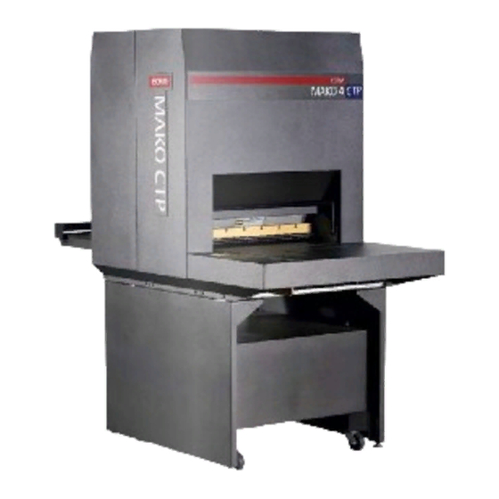
Safety Introduction to the System The Mako 4 CTP produces plates for use in the printing industry. Plates are manually loaded by positioning the plate in the pin registration system and closing the pinch rollers. Imaging of the plate is then started with the push of a button. -
Page 10: Laser Safety
Laser Safety Laser Product Classification The system is classified as a Class one (I) laser product which contains a Class 3B (IIIb) laser System. This classification means that the operator is exposed to no hazardous laser light during operation and maintenance. The laser itself, however, is a Class 3B (IIIb) laser device, and emits visible laser light which is considered hazardous by FDA published limits. - Page 11 Identification and Certification Label (ratings plate) The identification and certification label is attached to the back, exterior of the unit, above the pinch rollers. ECRM Incorporated, 554 CLARK ROAD, TEWKSBURY, MA. 01876 MANUFACTURED AT TEWKSBURY, MA. U.S.A. Model No.
- Page 12 AG45134 Rev. 2...
-
Page 13: Chapter 2: System Operation
System Operation Introduction This chapter explains how to operate the system. Parts are identified for ease of use. System set-up menus are defined and explained. Status messages and error messages, which are displayed on the control panel, are also covered. Parts of the System PINCH ROLLER BAR POWER SWITCH... - Page 14 sets of plates with different registration notch requirements is easily accomplished by changing the pin bar. The Control Panel The control panel allows you to interact with the platesetter. Commands and options are controlled through this device. LEDS EXPOSE ATTENTION ERROR PREV NEXT...
-
Page 15: Starting Up The System
The Pinch Roller Bar The pinch roller bar is used to open and close the pinch rollers. These high precision rollers control the plate during exposing. The pinch roller bar must be up (pinch rollers open) to load a plate and down (pinch rollers closed) to expose a plate. -
Page 16: Shutting Down The System
Shutting Down the System To shut down the system, turn off the power switch located on the lower right side of the machine. Depress zero (0) to turn the power OFF . Shut down the system only when the display reads ONLINE, and the second line is blank. (No operational message visible). -
Page 17: System Menu Options
Keys Moves you backward within the menu or moves the cursor backward PREV within the current menu item. Enter or exit the menu sub-system by pressing MENU from the ONLINE MENU or the OFFLINE state. Moves you forward within the menu or moves the cursor forward within NEXT the current menu item. -
Page 18: Menu Selection
Menu selection Setting Parameters Procedure Follow these steps to set the parameters in any menu. Step 1. Press MENU to enter the user menu system. Step 2. Press SELECT until the sub-menu you want is displayed on the LCD. Step 3. Press NEXT to enter the selected sub-menu. Step 4. - Page 19 User Preferences ONLINE/OFFLINE MENU MENU MENU SELECT USER USER TEST MENU OPTIONS PREFERENCES MAINTENANCE PATTERNS NEXT UNITS OF MEASURE NEXT AUDIO ALERTS NEXT SPINNER TIMEOUT NEXT HORIZONTAL MAGNIFICATION NEXT EXPOSE ATTENTION ERROR VERTICAL MAGNIFICATION NEXT IMAGE OFFSET NEXT IGNORE LASER PREV NEXT TEMP.
- Page 20 HORIZONTAL MAGNIFICATION 85.00% to 110.00% LIMITS Sets the size of the image in the horizontal direction from 85% to 110% of nominal. VERTICAL MAGNIFICATION 85.00% to 110.00% LIMITS Sets the size of the image in the vertical direction from 85% to 110% of nominal.
-
Page 21: User Maintenance Menu
User Maintenance Menu PROGRAM VERSIONS This user maintenance option displays version numbers of the installed software and firmware. The versions will be displayed as: VERSIONS JP0020 n.n JA1126 n “NEXT” TO CONTINUE Where JP0020 n.n is the part number and revision level of the controller software, and JA1126 n is the part number and revision level of the controller firmware. -
Page 22: Test Patterns Menu
This user maintenance option will run the media transport until the STOP button is pressed. This function is used to clean the transport. RUN MEDIA ROLLERS This user maintenance option will run the media rollers until the STOP button is pressed. This function is used to clean the rollers. DISPLAY ERROR LOG This user maintenance option presents system faults (up to a maximum of 20 faults) in chronological order. - Page 23 ONLINE/OFFLINE Test Patterns Menu MENU MENU MENU SELECT SELECT SELECT TEST USER USER MENU OPTIONS PATTERNS PREFERENCES MAINTENANCE NEXT TEST SELECT PATTERN NEXT MODE ENABLE *TEST PATTERNS SELECT NEXT DISABLE REVERSE IMAGE POLARITY *TEST PATTERN SELECTIONS NEXT NEXT BARS (HORIZONTAL) BARS (VERTICAL) BAR WIDTH PLATE LENGTH...
- Page 24 BAR SPACING 1 to 999999 Pixels OPTIONS This parameter specifies the width of the spaces between the lines in the Bar Test Patterns. IMAGE LENGTH 0.027” to 39.330” or 2 mm to 999 mm OPTIONS This parameter specifies the length of the test pattern to be recorded. IMAGE OFFSET (VERTICAL) OPTIONS 0.0000”...
-
Page 25: Status Messages
Punched plates are generally notch registered as opposed to edge registered. NOTCH DEPTH 0.000” to 1.000” or 00.0 mm to 25.4 mm OPTIONS By picking a value, you set the notch depth for test patterns. DISTANCE FROM NOTCH TO LEADING EDGE OPTIONS 2.125”... -
Page 26: Error Messages
EJECTING PLATE - Exposing is complete and the plate is being ejected onto the plate transport. ONLINE - The normal operating mode for the system. STARTING SPINNER - This message is accompanied by a progress bar when preparing to start an image and the spinner motor is stopped. TEST PATTERNS - Test Patterns mode has been selected in the Test Patterns Menu and the system is ready to produce a test pattern. - Page 27 Correcting Errors Step 1. If a plate is in the machine when the error occurs, remove the plate as explained in “Maintenance and Troubleshooting.” Step 2. Correct the condition that caused the error. Step 3. Press the control panel “OK” button. Step 4.
- Page 28 2-16 AG45134 Rev. 2...
-
Page 29: Chapter 3: Media Handling
Media Handling Introduction This chapter explains how to load and unload media, and how to install and remove a pin bar from the machine. Media Media thickness - 5.5 mil (0.14mm), 6 mil (0.15 mm), 8 mil (0.20mm), 10 mil (0.25mm), 12 mil (0.30mm) Media size - Minimum - 10”... - Page 30 • Removing Media from the Output Tray Mako 4 CTP does not have the ability to “know” which pin bar is loaded. Therefore, it is up to you to ensure the proper pin bar is loaded and the proper plate is loaded.
-
Page 31: Installing And Removing The Pin Bar
Installing and Removing the Pin Bar The pin bar provides alignment points that insure accurate plate registration. There are two types of pin bars: notch-registered and edge-registered. Notch- registered pin bars are for registering plates that are punched with a specific notch pattern. - Page 32 at the other end of the pin bar locks the bar in place in the channel. LATCH ALIGNMENT PIN REGISTRATION PINS Figure 3-3 Pin Bar Installing a Pin Bar Step 1. If necessary, remove the existing pin bar as explained in “Removing a Pin Bar”...
- Page 33 Step 4. Position the pin bar over the channel with the alignment-pin end at the front of the channel and the latch at the back of the channel. Step 5. Holding the pin bar at a 45 degree angle, snap the pin bar alignment pin into the hook, as shown in Figure 3-5.
-
Page 34: Loading Media
Loading Media The host computer will request a pin bar and plate to be loaded, and the Mako CTP will prompt you to load the plate. One of the following prompts appears on the control panel LCD: LOAD A PLATE <plate name>... - Page 35 PINCH ROLLER BAR POWER SWITCH TRANSPORT CONTROL PANEL PIN BAR INPUT TRAY FAN FILTER PEDESTAL FRONT VIEW REAR VIEW Figure 3-6 External View of the System Loading Edge-registered plates Step 1. Face the front of the recorder. Step 2. Raise the pinch roller bar to open the GREEN LED pinch rollers.
- Page 36 Step 5. Push the plate to the left so that the edge of the plate contacts the regis- tration pins in the pin bar. (See View A, Figure 3-7). PINCH ROLLERS PIN BAR EDGE OF PLATE REGISTRATION PIN PLATE VIEW A VIEW B Figure 3-7 Loading Edge-registered Plates Step 6.
- Page 37 Note: If the green LED is not staying illu- GREEN minated, the pin bar may not be fully seated. Remove and reinstall the pin bar, following the instructions above. EXPOSE ATTENTION ERROR Step 8. Holding the plate in position, lower the pinch roller bar .
- Page 38 PINCH ROLLERS REGISTRATION PIN PIN BAR PLATE NOTCH PIN BAR REGISTRATION PIN Figure 3-8 Loading Notch-registered Plates. Step 6. Watch for the green Expose LED to come on and stay on. This shows the plate is maintaining contact with the pins. If the LED goes out, you have lost pin contact.
- Page 39 Step 7. Holding the plate in position, lower the pinch roller bar. The green light will remain on if pin contact has been maintained and the recorder will prompt for the OK button to be pressed to start imaging. Note: If the green LED does not stay illuminated, open the pinch roller bar and go back to Step 5.
- Page 40 3-12 AG45134 Rev. 2...
-
Page 41: Chapter 4: Maintenance And Troubleshooting
Maintenance and Troubleshooting Introduction This chapter discusses: • General Maintenance • Using the User Maintenance Menu • Moving the System General Maintenance This chapter explains how to keep the system in clean, working order. Remember to shut the power off to the machine prior to performing any internal maintenance procedures. - Page 42 Two filtered fans run at all times to maintain an air flow inside the machine. Both fans use a 3.6” x 3.6” aluminum filter like the one shown shown at the right. (ECRM P/N FF0087). The filters can become clogged with dust and other debris if it is not cleaned regularly.
- Page 43 Step 2. Use the User Maintenance Menu to run the media rollers. See Figure 4-4. Step 3. Sparingly apply “Fantastik” (ECRM HB2456) to a clean, lint-free wipe. Step 4. As the rollers turn, gently wipe both the front and back rollers with the cloth, being careful to not ‘catch’...
- Page 44 Cleaning the Media Transport Belt Step 1. Use the User Maintenance Menu to run the transport. Step 2. Using a lint-free cloth moistened with “Fantastik” (ECRM HB2456), remove debris from the belt. Step 3. Using a second lint-free cloth moistened with alcohol, rub down the belt.
-
Page 45: Clearing Misfeeds
Clearing Misfeeds Two methods for clearing a misfeed are presented below. • Use Method 1 if you are using a notch-registered pin bar. • Use Method 2 if you are using an edge-registered pin bar. Method 1 Step 1. Lift the pinch roller bar to open the roller. Step 2. - Page 46 During imaging, the pinch roller bar is down and the registration pin is below the plate’s path of travel. If a misfeed or a power failure happens to occur and the plate gets “hung up” in the machine, you are advised not to raise the pinch roller bar. Doing so will raise the registration pin.
-
Page 47: Using The User Maintenance Menu
Using the User Maintenance Menu PROGRAM VERSIONS This user maintenance option displays version numbers of the installed software and firmware, as explained in Chapter 2. RUN TRANSPORT This user maintenance option will run the media transport until the STOP button is pressed. This function is used to clean the transport. User Maintenance Menu ONLINE/OFFLINE MENU... -
Page 48: Leveling The System
faults) in chronological order. TIME is the elapsed time since the latest power on. SESSION # is the total number of times the system has been turned on. DEVICE NAME identifies the system component that failed. ERROR is an indication of the nature of the fault. DISPLAY LASER LOG This user maintenance option presents status information about the system laser.
Need help?
Do you have a question about the Mako 4 CTP and is the answer not in the manual?
Questions and answers