Table of Contents
Advertisement
Advertisement
Table of Contents

Summary of Contents for ECRM Mako 4 CTP
- Page 1 Mako 4 CTP Operator Guide...
- Page 2 Proprietary Notice The information contained in this publication is the sole property of ECRM. It cannot be reproduced, in whole or in part, without the express written consent of ECRM. The information is believed to be accurate as of the publication date, but it is subject to change without notice due to continuing product development.
-
Page 3: Table Of Contents
Table of Contents Chapter Page Number Chapter 1: Requirements and Safety............1-1 Introduction to the System ..............1-1 System Requirements ...............1-1 Laser Safety ..................1-2 Regulatory Information ..............1-3 Chapter 2: System Operation ..............2-1 Introduction ..................2-1 Main Parts of the Platesetter ............2-2 Starting Up the System ..............2-5 Shutting Down the System ...............2-5 Using the Control Panel ..............2-6 Operator Menus ................2-8... - Page 4 AG45134 Rev. 3...
-
Page 5: Organization Of This Guide
The Mako 4 CTP employs a Class 3B laser. This guide contains important safety information and regulatory information about the laser. You should read this information thoroughly before operating the system or performing the procedures described in this guide. - Page 6 Chapter 3: Media Handling Chapter 3 provides instructional information on how to load media. Guidelines for handling media are also provided. Chapter 4: General Maintenance and Troubleshooting Chapter 5 covers general maintenance items that can be performed by the operator. This chapter includes troubleshooting tips and a procedure for re-locating or moving the system.
-
Page 7: Chapter 1: Requirements And Safety
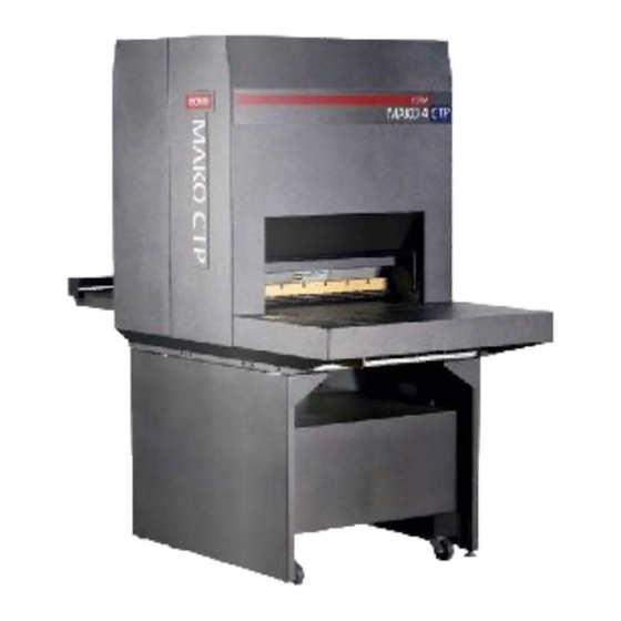
Safety Introduction to the System The Mako 4 CTP images printing plates. Plates are manually loaded by positioning the plate in the pin registration system and closing the pinch rollers. Imaging of the plate starts with the push of a button. -
Page 8: Laser Safety
Laser Safety Laser Product Classification The system is classified as a Class one (I) laser product which contains a Class 3B (IIIb) laser System. This classification means that the operator is exposed to no hazardous laser light during operation and maintenance. The laser itself, however, is a Class 3B (IIIb) laser device, and emits visible laser light which is considered hazardous by FDA published limits. -
Page 9: Regulatory Information
Regulatory Information Electromagnetic Emissions DOC - Canada The Canadian Department of Communications requires compliance with the Radio Interference Regulations, ICES -003. This digital apparatus does not exceed the Class A limits for radio noise emissions from digital apparatus set out in the Radio Interference Regulations of the Canadian Department of Communications. - Page 10 Identification and Certification Label (ratings plate) The identification and certification label is attached to the back, exterior of the unit, above the pinch rollers. ECRM Incorporated, 554 CLARK ROAD, TEWKSBURY, MA. 01876 MANUFACTURED AT TEWKSBURY, MA. U.S.A. Model No.
-
Page 11: Chapter 2: System Operation
System Operation Introduction A complete Mako 4 system includes a control workstation, CtServer software, a power conditioner, and a Mako 4 platesetter. Workstation The control workstation connects directly to the platesetter and runs the CtServer software. Operating instructions for the workstation are provided with the workstation. -
Page 12: Main Parts Of The Platesetter
Platesetter The platesetter outputs the imaged plates. Main Parts of the Platesetter PINCH ROLLER BAR POWER SWITCH MEDIA TRANSPORT CONTROL PANEL PIN BAR INPUT TRAY PEDESTAL ILTER FILTER POWER CORD REAR VIEW FRONT VIEW Figure 2-1 Main Parts of the Platesetter The Power Switch The power switch controls ac power to the system. -
Page 13: The Control Panel
The Power Cord The power cord plugs into a receptacle located just below the power switch. Note: In order for the system to work properly, the platesetter, the CtServer computer, and the computer monitor must all be plugged into the system power conditioner. Be advised that if the devices are not plugged into the power condi- tioner, damage resulting from voltage spikes, brownouts, etc., will NOT be covered by the warranty. - Page 14 The Input Tray The input tray is used to position the plate for exposing. The plate is placed on the input tray and gently slid to engage the registration pins. A groove is provided in the surface of the input tray to provide a convenient place to push the plate forward.
-
Page 15: Starting Up The System
Fan Filters The system uses 2 fan filters. The filters slide into slots on either side of the unit (see Figure 2-1). The Media Transport The media transport provides for automated delivery of media to a customer-supplied online processor. The Pedestal The pedestal is a specially designed base for the platesetter. -
Page 16: Using The Control Panel
Using the Control Panel When you first install the system, you must review and set all the menu parameters. Advance through the menu items and verify or change them as needed. When the menu parameters are completed, the system is ready for use. Accessing Menus Access menus from the system control panel. - Page 17 Keys Moves you backward within the menu or moves the PREV cursor backward within the current menu item. Enter or exit the menu sub-system by pressing MENU MENU from the ONLINE state. Moves you forward within the menu or moves the cursor NEXT forward within the current menu item.
-
Page 18: Operator Menus
Operator Menus There are three operator menu options: • User Preference Menu (See page 9). • User Maintenance Menu (See page 12.) • Test Pattern Menu (See page 14.) Menu Selection Follow these steps to set the parameters in any menu. Step 1. -
Page 19: User Preferences Menu
User Preferences Menu UNITS OF MEASURE ENGLISH (inches) or METRIC (millime- OPTIONS ters) The selected units of measure apply to all numeric measurement values in various menus. AUDIO ALERTS OPTIONS ENABLED or DISABLED This menu item allows you to disable or to enable the audible alarms for the following conditions: Error conditions, Power-up, Image complete HORIZONTAL MAGNIFICATION... - Page 20 User Preferences Menu ONLINE MENU User Test Test SELECT User SELECT SELECT Test Preferences Patterns Preferences Maintenance Patterns Patterns NEXT User Menus Units of Measure NEXT Audio Alerts NEXT Horizontal Magnification NEXT Vertical Magnification NEXT Image Offset NEXT Ignore Laser Temp.
- Page 21 IMAGE OFFSET -0.300” to +0.300” (-7.62mm to LIMITS +7.62mm) The image may be shifted to the left with a negative (-) value, or to the right with a positive (+) value by up to 0.300 inches. Press PREV to access the (+) and (-) sign. IGNORE LASER TEMPERATURE ERRORS YES or NO OPTIONS...
-
Page 22: User Maintenance Menu
User Maintenance Menu PROGRAM VERSIONS This user maintenance option displays version numbers of the installed software and firmware. The versions will be displayed VERSIONS JP0020 n.n JA1126 n “NEXT” TO CONTINUE Where JP0020 n.n is the part number and revision level of the controller software, and JA1126 n is the part number and revision level of the controller firmware. - Page 23 who sometime request the information over the phone during service calls. User Maintenance Menu ONLINE MENU User User Test SELECT SELECT SELECT Test Preferences Maintenance Patterns Patterns User Menus NEXT Program Version SELECT Transport SELECT Media Rollers SELECT Display EXPOSE ATTENTION ERROR Error Log...
-
Page 24: Test Patterns Menu
Test Patterns Menu The test pattern menu is used to select and run one of the pre programmed test patterns. (See the “TEST PATTERN SELECTIONS” sidebar in Figure 2-2-8 on page 15 for a list of the test patterns). The test pattern menu configuration options are summarized below. Note: Some of options listed below are test- pattern specific. -
Page 25: Test Patterns
Test Patterns ONLINE MENU SELECT SELECT SELECT User User Test Test Test Preferences Patterns Preferences Maintenance Patterns Patterns NEXT User Menus SELECT SELECT Test Pattern Disable Enable Mode NEXT NEXT ATTERN ELECTIONS ATTERNS SEE SIDEBAR AT RIGHT NEXT ROOP EDIA ROOP COPE ASER... - Page 26 IMAGE LENGTH 0.027” to 39.330” or 2 mm to 999 mm OPTIONS This parameter specifies the length of the test pattern to be recorded. IMAGE OFFSET (VERTICAL) 0.0000” to 39.330” or 0 mm to 999 mm OPTIONS This parameter specifies the distance from the leading edge of the plate to the first line of the image.
- Page 27 PLATE WIDTH 9.922” to 25.472” or 253.8 mm to OPTIONS 646.9 mm By picking a value, you set the plate width for test patterns. PLATE LENGTH 9.992” to 36.574” or 253.8 mm to OPTIONS 928.9 mm By picking a value, you set the plate length for test patterns. PLATE IS NOTCH REGISTERED YES or NO OPTIONS...
- Page 28 HORIZONTAL MAGNIFICATION 85.00% to 110.00% LIMITS Sets the size of the image in the horizontal direction from 85% to 110% of nominal. VERTICAL MAGNIFICATION 85.00% to 110.00% LIMITS Sets the size of the image in the vertical direction from 85% to 110% of nominal.
-
Page 29: Running A Step Wedge Test Pattern
Running a Step Wedge Test Pattern The step wedge test pattern is used to set the proper exposure for a polymer plate. Here s how to run step wedge test plate. Preparing to Run the Step Wedge Test Pattern Step 1. Under safelight conditions, place a test plate on the input shelf. Step 2. - Page 30 Step 3. Press NEXT, and then repeatedly press SELECT until the Step Wedge pattern displays. Then, press NEXT again. Step 4. Set Horizontal resolution to the required resolution. Step 5. Set Vertical resolution to the required resolution. Step 6. Set Exposure to the value you wish to expose the wedge (range is 0-255.) Step 7.
-
Page 31: Status Messages
Status Messages During operation, the system displays information that indicates the current condition of the system and of any jobs in process. The status messages appear on the control display. PREPARING TO EXPOSE - The system is starting the spinner and moving the plate to the recording start position. -
Page 32: Error Messages
Error Messages During operation, error conditions may occur that require your intervention. These messages will appear on the system display panel and the error indicator LED will light. Additionally, if enabled, the alarm will also sound. Operator-Correctable Errors The error messages that you can clear are listed below. COVERS ARE NOT SECURE - This error is displayed when one of the system covers are not secure. -
Page 33: System Configuration Display
Step 3. Press the control panel OK button. Step 4. Resume normal operation. System Configuration Display Should you ever call for service, your service provider may ask you to relate the information that appears on the System Configuration display. To view the display: Step 1. - Page 34 2 - 24 AG45134 Rev. 3...
-
Page 35: Chapter 3: Media Handling
Media Handling Introduction This chapter explains how to load and unload media, and install and remove a pin bar. Media Media thicknesses - 5.5 mil (0.14mm), 6 mil (0.15 mm), 8 mil (0.20mm), 10 mil (0.25mm), 12 mil (0.30mm) Media size, minimum 10”W x 13”L (254mm x 330mm), Media size, maximum 25.4”W x 36.5”L (645 x 927mm) Configuration - Prepunched Press Grooves or Edge Register... -
Page 36: Media Handling
• Removing Media from the Output Tray Mako 4 CTP does not have the ability to “know” which pin bar is loaded. It is up to you to make sure the pin bar is appropriate for the plate that is being used. -
Page 37: Installing And Removing The Pin Bar
Installing and Removing the Pin Bar The pin bar provides alignment points that insure accurate plate registration. There are two types of pin bars: notch-registered and edge- registered. Notch-registered pin bars are for registering plates that are punched with a specific notch pattern. This pattern matches up with the pins in both the Mako CTP and the press clamp. - Page 38 Figure 3-3 shows the main parts of the pin bar. The alignment pin helps keep the pin bar in proper alignment with the rest of the media handling system. The latch at the other end of the pin bar locks the bar in place in the channel.
- Page 39 FRONT OF CHANNEL HOOK Figure 3-4 Alignment Pin Hook Step 4. Position the pin bar over the channel with the alignment-pin end at the front of the channel and the latch at the back of the chan- nel. Step 5. Holding the pin bar at a 45 degree angle, snap the pin bar align- ment pin into the hook, as shown in Figure 3-5.
- Page 40 Step 7. Firmly press the center of the pin bar down to insure that it is seated properly. HOOK ALIGNMENT PIN CHANNEL Figure 3-5 Setting the Alignment Pin in the Hook Removing a Pin Bar Step 1. Push the pin bar latch forward to disengage the latch. Step 2.
-
Page 41: Loading Media
Loading Media The host computer will request a pin bar and plate to be loaded, and the Mako CTP will prompt you to load the plate. One of the following prompts appears on the control panel LCD: LOAD A PLATE <plate name>... - Page 42 plate registration. Always handle and position the plate gently and carefully. Thin plates are especially susceptible to dings and dents. PINCH ROLLER BAR POWER SWITCH TRANSPORT CONTROL PANEL PIN BAR INPUT TRAY FAN FILTER PEDESTAL FRONT VIEW REAR VIEW Figure 3-6 External View of the System Loading Edge-registered plates Step 1.
- Page 43 Step 2. Raise the pinch roller bar GREEN LED to open the pinch rollers. Be sure the pinch roller is fully raised. If it is not, ERROR EXPOSE ATTENTION the green Expose LED will not light. Step 3. Verify the requested pin bar is loaded.
- Page 44 Step 5. Push the plate to the left so that the edge of the plate contacts the registration pins in the pin bar. (See View A, Figure 3-7). PINCH ROLLERS PIN BAR EDGE OF PLATE EGISTRATION PLATE VIEW A VIEW B Figure 3-7 Loading Edge-registered Plates Step 6.
- Page 45 If the LED goes out, you have lost pin contact. Move the plate out and to the right slightly, and then back in and to the left until the green LED stays on. Be careful to not apply so much pres- sure to the plate that the registration pins dent the plate.
- Page 46 Loading Notch-registered plates Step 1. Face the input tray. Step 2. Raise the pinch roller bar to open the pinch rollers. Be sure the pinch roller is fully raised. If it is not, the green Expose LED will not light. Step 3.
- Page 47 PINCH ROLLERS REGISTRATION PIN NOTCH PIN BAR PLATE PIN BAR REGISTRATION PIN Figure 3-8 Loading Notch-registered Plates. Step 6. Watch for the green Expose LED to come on and stay on. This shows the plate is maintaining contact with the pins. If the LED goes out, you have lost pin contact.
- Page 48 them again until the green LED stays on.Be careful to not apply so much pressure to the plate that the registration pins dent the plate. Use one finger/thumb to apply minimal pressure to the center of the plate while lifting the plate slightly. Note: If the green LED is not staying illuminated, the pin bar may not be fully seated.
-
Page 49: Chapter 4: Maintenance And Troubleshooting
Maintenance and Troubleshooting Introduction This chapter discusses: • General Maintenance • Moving the System General Maintenance This chapter explains how to keep the system in clean, working order. Remember to shut the power off to the machine prior to performing any internal maintenance procedures. Use only the recommended cleaner. - Page 50 Two filtered fans run at all times to maintain an air flow inside the machine. Both fans use a 3.6” x 3.6” aluminum filter like the one shown in the next figure. (ECRM P/N FF0087). 4 - 2 AG45134 Rev. 3...
- Page 51 The filters can become clogged with dust and other debris if it is not cleaned regularly. A clogged filter can result in the loss of internal pressure and increase the possibility of a system malfunction. Clean the filters whenever they show signs of contamination with dust or other debris Here’s how to remove and...
- Page 52 Step 1. Open the pinch roller bar to open the rollers. Step 2. Use the User Maintenance Menu to run the media rollers. Step 3. Sparingly apply Fantastik (ECRM HB2456) to a clean, lint-free wipe. Step 4. As the rollers turn, gently wipe both the front and back rollers with the cloth, being careful to not catch the cloth in the rollers.
- Page 53 Step 7. Wipe gum-contaminated pinch roller o-rings with a water-damp- ened low-lint cloth. Step 8. If water fails to remove the gum, use ECRM PH0046 roller cleaner. (Do NOT use alcohol or a general purpose cleaner to clean the rollers.) Step 9.
-
Page 54: Clearing Misfeeds
Cleaning the Media Transport Belt Step 1. Use the User Maintenance Menu to run the transport. Step 2. Using a lint-free cloth moistened with Fantastik (ECRM HB2456), remove debris from the belt. Step 3. Using a second lint-free cloth moistened with alcohol, rub down the belt. - Page 55 INTERNAL REGISTRATION PIN REAR PINCH ROLLER FRONT REGISTRATION PIN PINCH ROLLER PLATE PIN BAR NOTE The Internal Registration Pin goes up when the Pinch Roller Bar is raised REGISTRATION PIN and goes down when the Pinch Roller Bar is lowered. Figure 4-4 Internal Registration Pin During imaging, the pinch roller bar is down and the registration pin is below the plate’s path of travel.
- Page 56 INTERNAL EGISTRATION PLATE PLATE VIEW A VIEW B Plate not over the pin Plate over the pin Figure 4-5 Plate Positions over the Registration Pin To insure against this happening, use the following procedure to remove the plate: Step 1. Do not raise the pinch roller bar or power off the machine. Step 2.
-
Page 57: Moving The System
Step 3. Exercise the PREV and NEXT buttons as required until the plate out all the way of the machine. Step 4. Press the OK button. This turns off the blinking error light and clears the the error message from the display. Step 5. - Page 58 Step 4. Turn all four levelling feet of the platesetter down until they just touch the floor. Step 5. Continue to turn leveling feet until the system is level, front to back and side to side. 4 - 10 AG45134 Rev. 3...
Need help?
Do you have a question about the Mako 4 CTP and is the answer not in the manual?
Questions and answers