Table of Contents
Advertisement
Advertisement
Table of Contents

Related Manuals for Fox F31-462A

Summary of Contents for Fox F31-462A
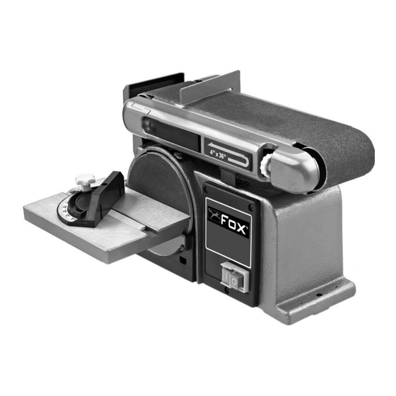
- Page 1 BELT SANDER 100mm AND DISC 150mm (Fox Model F31-462A)
- Page 2 SUMMARY INSTRUCTION MANUAL 3-28 EXPLODED VIEW 29-30 WIRING SCHEME DECLARATION OF CONFORMITY...
-
Page 3: Table Of Contents
Belt sander 100mm and disc 150mm (FOX Model F31-462A) TABLE OF CONTENTS Safety rules Page 5 General safety rules Page 6 Additional safety requirements for sanders and belt drive Page 8 Environmental protection Page 9 ... - Page 4 - Sanding an end surface with the guide tabs Page 23 - Sanding with the sanding belt - horizontal/vertical Page 23 - Sanding a surface on the sanding belt Page 23 - Sanding a curved piece Page 24 Maintenance Page 25 - General information Page 25...
-
Page 5: Safety Rules
Work out a safer method. REMEMBER: safety is everyone's responsibility. This tool was designed for specific uses. FOX strongly recommended not to change it and / or used for any application other than that for which it was designed. If questions arise about a particular application, DO NOT use the tool until you have contacted FOX to determine if the tool can be used in this way. -
Page 6: General Safety Rules
GENERAL SAFETY RULES 1. Keep the work area clean. Work areas and cluttered benches invite injuries. 2. Avoid a dangerous environment. Do not expose power tools to rain and do not use in damp or wet locations. Keep the work area well lit. Do not use the tool in presence of flammable gases or liquids. 3. - Page 7 20. Unplug the tool when not in use, before servicing and when changing accessories such as blades, bits, cutters, etc. 21. Keep keys and adjusting wrenches. Check that all keys and adjusting wrenches have been removed from the tool before turning it on. 22.
-
Page 8: Additional Safety Requirements For Sanders And Belt Drive
ADDITIONAL SAFETY RULES FOR SANDERS 1. ALWAYS UNPLUG the power sander before making any repairs, changing the belt or disc, cleaning or maintenance. 2. DO NOT USE the sander before it is completely assembled and installed according to instructions. 3. PROTECT your eyes with safety glasses and use a dust mask 4. -
Page 9: Environmental Protection
ENVIRONMENTAL PROTECTION INFORMATION TO USERS Under the terms of art. 13 of Legislative Decree of 25 July 2005, No. 151 "Application of Directives 2002/95 / EC, 2002/96 / EC and 2003/108 / EC relating to the reduction of the use of hazardous substances in electrical and electronic, as well as waste disposal ", it states the following: •... -
Page 10: Symbols
SYMBOLS Always wear protective goggles when using this machine. Read and understand the instruction manual before using the machine Always wear a protective mask if the operation is dusty. Always wear ear defenders when using the machine. Heavy lift. Transporting the machine requires two people. Product meets relevant CE standards. -
Page 11: Electrical Connections
CONNECTING THE SAW ELECTRICAL CONNECTIONS ELECTRICAL CONNECTION Your machine has a precision built electric motor. It must be connected to a power supply of 230V, 50 Hz. If your machine does not operate when plugged into an outlet, double check the power supply. EARTHING INSTRUCTIONS In case of malfunction or short circuit, grounding provides a path of least resistance for electric current to reduce the risk of electric shock. -
Page 12: Recommendations Of Use
EXTENSION CORDS When using the power tool at some distance from the socket, be sure to use an extension cord powerful enough to carry the current that the tool needs. An undersized extension cord will cause a voltage drop in the line leading to overheating and power loss. -
Page 13: Specifications
SPECIFICATIONS Motor : 370 W Voltage and frequency : 230 V – 50 Hz Sanding strip Width : 100 mm Length : 914 mm Speed : 450 m/mm Length of the table : 360 mm Tilt : 0° to 90° Sanding disc Diameter : 152 mm... -
Page 14: Unpacking And Cleaning
belt and disc, as well as the piece you are working against the disc or belt. It is advisable to check the engine, its ventilation system and air routes. Check the condition of the cruise control, the tension of the band and the material to be ground. Properly maintain the workpiece. The quoted values are emission values calculated using standard values and are not representative of use within the workplace. -
Page 15: Parts Identification
PARTS IDENTIFICATION... - Page 16 TILT INDICATOR The work table is supplied with a tilt indicator; it allows adjustment of the inclination of the table to 45°. SANDING BELT TENSION LEVER This lever allows you to remove the tension on the sanding belt for easy replacement of the sanding belt. TILTING SANDING BELT Use a 6mm Allen key to release the band.
-
Page 17: Mounting
SANDING DISC The sanding disc is located on the side of the tool. On / Off SWITCH The sander has an easily accessible power switch. CENTERING BUTTON The centering button allows the sanding belt to be centered. STRIP BACKSTOP To help keep the piece to be sanded on the sanding belt. The supplied backstop may differ from the illustration. WORKTABLE The machine has a rugged work table which provides a stable support surface for the sanding with the disk or sanding belt. -
Page 18: Mounting The Sanding Disc And Housing
MOUNTING THE SANDING DISC AND HOUSING Figure 4 Remove the back sheet of the sanding disc. Align the perimeter of the sanding disk with the support plate; firmly apply to ensure it sticks. Place the housing against the lower 1/3 of the disc; align the holes as shown in Figure 4. -
Page 19: Assembling The Worktable For Use With The Sanding Disc
ASSEMBLING THE WORKTABLE FOR USE WITH THE SANDING DISC Figure 6 To use the worktable with the sanding disc : Insert the table mounting rod into the hole as shown in Figure 6. Position the worktable no more than 1.6mm (1/16 inch) from the sanding surface. ... -
Page 20: Installing The Support Plate
INSTALLING THE SUPPORT PLATE Figure 8 • Position the workpiece support plate over the holes on the side of the tool housing, as shown in Figure 8. • Use an Allen key to tighten the screws (do not forget to use the washers). -
Page 21: Settings
SETTINGS DANGER ! Turn off and unplug the sander from the power source and wait until the belt and disk are completely stopped before making any adjustments, belt changes or maintenance to the unit. CENTERING THE SANDING BELT Figure 11 Checking the centering of the sanding belt : •... -
Page 22: Angle Between The Table And Sanding Disc
ANGLE BETWEEN THE TABLE AND SANDING DISC Figure 12 • Unplug the machine. • Using a bracket (not included), check the angle between the worktable and sanding disc. • If the angle is not exactly 90°, loosen the table lock knob and tilt the table. -
Page 23: Sanding An End Surface With The Guide Tabs
SANDING AND END SURFACE WITH THE GUIDE TABS Figure 15 A mitre gauge is supplied with the machine for a specific job. We recommend the use of the mitre gauge for sanding a piece of wood with the sanding disc. Note: You should always move the piece you are sanding across the sanding disc from the left side to the right side. -
Page 24: Sanding A Curved Piece
WATCH OUT : Never attempt to sand the end surfaces of a piece on the free drum; this SANDING A CURVED PIECE could cause pieces to shear off. Ignoring this warning may result in serious injury. Figures 18 and 19 Sanding a concave surface on the sanding belt : Always sand a concave surface on the free drum as shown in Figure 18. -
Page 25: Maintenance
MAINTENANCE DANGER : Turn off and unplug the sander from the power source and wait until the belt and disc have completely stopped before making any adjustments, changing the belt or any maintenance on the unit. GENERAL INFORMATION Any damage or malfunction found when inspecting the sander must be repaired immediately by qualified personnel. Before each use, check that the guards are in perfect condition, and clean the machine after each use, taking care to remove dust and sawdust. -
Page 26: Changing The Drive Belt
CHANGING THE DRIVE BELT Figure 20 • Using a screwdriver, remove the screws holding the pulley cover. • Remove the cover. • Move the sanding belt to the vertical position as shown in Figure 20 to access the belt tension. •... -
Page 27: Troubleshooting
All tools and accessories are built and tested using modern and safe manufacturing techniques. But if a tool fails in spite of this, repairs must be performed by an authorised service centre. You can contact the FOX service centre on 01592 656188. -
Page 28: Dart Tool Group Guarantee
FOX Power Tools and accessories which, upon examination, prove to be defective in workmanship or material. The warranty period for the FOX branded products is one year for parts and labour and three years for parts only. The guarantee does not include repair, labour or parts requiring replacement because of misuse, abuse, or normal wear and tear. - Page 29 F31-462A BELT SANDER 100mm AND DISC 150mm...
- Page 30 F31-462A BELT SANDER 100mm AND DISC 150mm N° Product Code N° Product Code F31462A-1 F31462A-56 F31462A-2 F31462A-57 F31462A-3 F31462A-58 F31462A-4 F31462A-59 F31462A-5 F31462A-60 F31462A-6 F31462A-61 F31462A-7 F31462A-62 F31462A-8 F31462A-63 F31462A-9 F31462A-64 F31462A-10 F31462A-65 F31462A-11 F31462A-66 F31462A-12 F31462A-67 F31462A-13 F31462A-68 F31462A-14...
-
Page 31: Wiring Scheme
WIRING SCHEME... -
Page 32: Declaration Of Conformity
DUNNIKIER BUINESS PARK KIRKCALDY, UK, KY1 3PD Tel. +44 (0) 1592 652946 Fax: +44 (0) 1592 654854 Declares that the: BELT SANDER AND DISC (F31-462a) is in compliance with the regulations included in the Directives: CEE 2006/42-2004/108- 2006/95 Person authorized to create the technical file: Robert Paterson 06.05.2011...
Need help?
Do you have a question about the F31-462A and is the answer not in the manual?
Questions and answers