Table of Contents
Advertisement
Panel Saw
Owner's Manual
C-Series, H-Series, 6400 & 6800
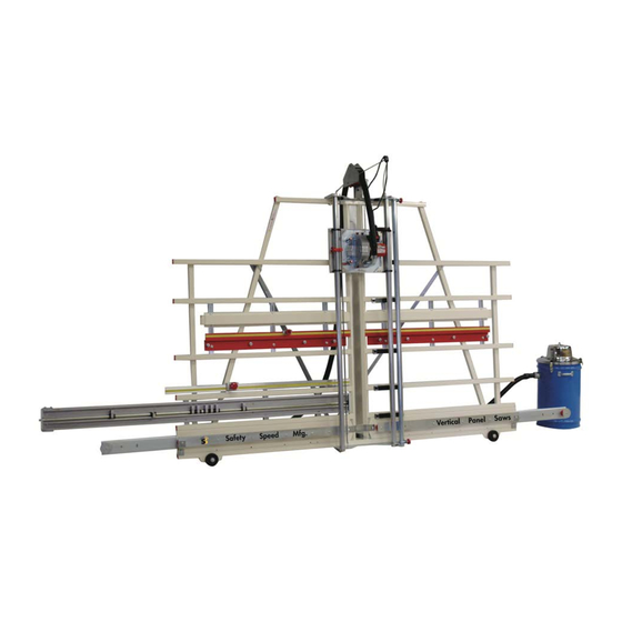
H-Series vertical panel saw with optional accessories
Proudly made in the USA
www.SafetySpeed.com
Read and understand this manual before operating this tool. Failure to follow the safety precautions and
instructions can result in serious injury or death. Keep this manual in an accessible and safe location for
future reference.
Advertisement
Table of Contents

Related Manuals for SafetySpeed 6400


Summary of Contents for SafetySpeed 6400
-
Page 1: Panel Saw
Panel Saw Owner’s Manual C-Series, H-Series, 6400 & 6800 H-Series vertical panel saw with optional accessories Proudly made in the USA www.SafetySpeed.com Read and understand this manual before operating this tool. Failure to follow the safety precautions and instructions can result in serious injury or death. Keep this manual in an accessible and safe location for... -
Page 2: Limited Warranty
Note: The Model and Serial No. label can be found on the upper, left side of the frame, when facing the saw. Model No: ____________________________ Serial & Model Label Serial No: _____________________________ Safety Speed Mfg. 13943 LINCOLN ST. NE HAM LAKE, MN 55304 Figure 1: Serial & Model label (6400 shown) 763-755-1600... -
Page 3: Table Of Contents
CONTENTS Safety…………………………………………………………………. Safety & Warning Label Placement…………………………………………. Safety & Warning Labels Identified….…………………………………….…. 5 Safety Procedures……………………………………………………………... 6 Electrical Safety………………………………………………………………... 10 Extension Cords ..................11 Short-Circuit Protection ................12 Vertical Panel Saw Components………………………………………….…. 12 Installation ..................Tools Required for Installation ..............13 Operating Environment ................ -
Page 4: Safety
Keep this manual in an accessible and safe location for future reference. Electronic copies of this manual are available at www.safetyspeed.com. Printed copies are available by calling SSM 763-755-1600. Indicates a hazardous situation which, if not avoided, will result in death or serious injury. -
Page 6: Safety Procedures
When using electric tools, always follow basic safety precautions to reduce the risk of fire, electric shock, and personal injury. READ AND SAVE ALL INSTRUCTIONS FOR FUTURE USE. Before use, be sure everyone using this tool reads and understands this manual as well as any labels packaged with or attached to the tool. 1. - Page 7 17. AVOID ACCIDENTAL STARTING. Be sure your tool is turned off before plugging it in. Do not use the tool if the power switch does not turn it on and off. Observe correct lockout/tag out procedures when performing maintenance on the tool. 18.
- Page 8 c. SECURE WORK PROPERLY. If a piece is supported on both sides of the cut in such a way that it allows the material to bow and pinch the blade, it may produce kickback. Do not cut pieces smaller than the saw carriage.
- Page 9 32. DO NOT PLACE YOUR HANDS ON OR UNDER THE SAW CARRIAGE OR IN THE PATH OF THE BLADE. Do not try to retrieve a piece of cut material while the blade is rotating. This symbol is to remind you: 33.
-
Page 10: Electrical Safety
Some dust created by power sanding, sawing, grinding, drilling, and other construction activities contains chemicals known to cause cancer, birth defects or other reproductive harm. Some examples of these chemicals are: • Lead from lead-based paint • Crystalline silica from bricks and cement and other masonry products, and •... -
Page 11: Extension Cords
Your tool must be plugged into an appropriate outlet, properly installed and grounded in accordance with all codes and ordinances. The plug and outlet should look like those in Figure 3. Figure illustrates a temporary adapter available for connecting grounded plugs. The green rigid ear or lug extending from the adapter must be connected to a permanent ground such as a properly grounded outlet box or receptacle. -
Page 12: Short-Circuit Protection
General guidelines are as follows: 120 volts: 20-amp protection These models can include: C4, C5, H-series, 6400/6800 220 volt: 10 amp protection These models can include: C4, C5, H-series, 6400/6800 Reference your motor label and your local codes before installation. -
Page 13: Installation
NOTE: Additional tools may be required for installing accessories. • 7/16” wrench (C & H Series) • 5/8” wrench (C & H Series) • 9/16” blade wrench (6400 & 6800) included • ¼” blade hex wrench (C & H Series) included Operating Environment For safe operation, install the tool in an area that is well lit. -
Page 14: Inventory
(Fig. 7) being careful not to damage panel saw. Cut around base. NOTE: Do not cut through (across) crate base (Fig.8). NOTE: 6400 Only, cut between block of wood and base of wood crate, supporting counter weight in back. This will ease removal of wood block supporting counter weight. - Page 15 Figure 8: Cutting along base of wood crate, do not cut through (across) base 3. Cut top of crate near saw frame, to release crate, Fig. 9. Remove back side of crate as it should be loose from saw and crate. Make sure helper is holding saw frame. Figure 9: Cutting top (back) of wood crate 4.
-
Page 16: Machine Assembly
Counterbalance. A Counterbalance is used on Models C4, C5 and H-Series to offset the weight of the carriage and saw. The 6400 and 6800 models use a Counterweight system that is factory installed. When unpacking a 6400 or 6800, loosen carriage lock (Fig. - Page 17 1. Remove the two 1/4-20 x 5/8” carriage bolts, nuts, and washers (Fig. 12) from the counterbalance. 2. Set the Counterbalance on top of the tool frame, slightly off-center to the right, so that the cable is aligned vertically with an oval hole near the top/right of the Saw Carriage (Fig.11 & 12). NOTE: Do not mount the Counter balance in the center holes.
- Page 18 Figure 14: Attaching Counterbalance Cable Bend the Cable Clip (Fig. 15) tabs forward by hand, so they look like the ones in Fig. 12 & 13. Figure 15: Cable Clip 7. Loosen the Carriage Lock (Fig. 13) and lower the Saw Carriage until the Cable Clip is fully exposed, tighten Carriage Lock (Fig.
- Page 19 This bolt (#11) is factory-set and does not require adjustment when the tool is being installed. 5. Tighten the two bottom nuts first (Fig. 17, #7), and the top nut (#12) last. Models 6400, 6800 The Models 6400 and 6800 are shipped with the saw motor already mounted.
- Page 20 Figure 17: Mounting the Saw Motor (C4, C5, H4, H5 & H6) DETAIL A SCALE 1 : 4 Installing a Blade C & H Series 1. Observe appropriate lock-out/tag-out procedures to insure the tool cannot accidentally be powered. 2. Select the correct blade for your needs. Refer to “Selecting a Blade”, page 27. IMPORTANT: Because the saw blade must be carefully matched to the materials being cut, Safety Speed does not supply a blade as standard equipment on the saw.
- Page 21 7. Loosen the carriage lock and allow the saw carriage to return to the top of the guides. To reduce the risk of injury, do not operate the tool without the blade guard in place. Installing a Blade 6400 & 6800 Observe appropriate lock-out/tag-out procedures to insure the tool cannot accidentally be powered.
- Page 22 Always install the blade guard before operating the saw. The guard is shipped with two (6400 & 6800, Fig. 21) or three (C & H series, Fig. 20) torque knobs (#22) installed, depending on the model. Remove the knobs to install the guard. Be sure to leave the rubber washers on the torque knobs, as they prevent the knobs from slipping.
- Page 23 Figure 20: Installing the Blade Guard (Models C4, C5, H4, H5, Figure 21: Installing the Blade Guard (Models 6400, 6800) Adjusting the Crosscut Rulers The saw has one rip ruler mounted vertically, and two crosscut rulers, one attached to the frame on each side of the saw.
- Page 24 Figure 22: Installing the Cord Keeper Rubber Stopper Cord Keeper Figure 23: Cord keeper installed 2. Remove the rubber stopper from the ring in the cord keeper. See Fig. 23. Uncoil the cord from the motor, and place the plug end through the ring as shown, Fig. 24. Cord Keeper Rubber Stopper Cord...
-
Page 25: Operation
4. Pull the cord keeper down so it is roughly parallel to the floor as shown. Pull the cord up to remove any slack in it. Then open the rubber stopper and pull it over the cord with the small end of the taper on the bottom. Press the rubber stopper into the ring on the cord holder, Fig.24. - Page 26 Max. Height 50 in.(1270mm) 50 in.(1270mm) C5/H5 64 in.(1625mm) 74 in.(1880mm) 6400 64 in.(1625mm) 6800 74 in.(1880mm) Work piece Thickness Maximum thickness of a work piece to be cut with SSM saws and routers is: • 1-3/4” (45mm) on all models*.
-
Page 27: Selecting A Saw Blade
Selecting a Saw Blade The saw blade must be carefully matched to the materials being cut. Improper blade selection can result in reduced tool life, inaccurate and poor quality cuts, and safety risks. NOTE: The following table lists some recommended blades for certain applications. If in doubt, consult with your machinery dealer, or with our customer service department (763-755-1600), to determine the best blade for your cutting needs. -
Page 28: Basic Operating Functions
Index Pins Blade Guard Spindle Lock Figure 27: Basic Operating Controls and Components (6400 & 6800) Removing and Reinstalling the Blade Guard (Dust Bonnet) Unplug Saw before adjusting The blade guard (Fig. 28 & 29, #21) is attached to the carriage with torque knobs (Fig. 28 & 29, #22). Remove the torque knobs to remove the guard. -
Page 29: Changing The Blade
2. Remove the blade guard see “Removing and Installing the Blade Guard” and (Fig. 28 & 29, #21). 3. To keep the spindle from turning while you loosen the arbor bolt (C & H Fig. 30, #12) or (6400 & 6800 Fig. 31, #12) push the spindle lock (#16) located on the under-side of the saw motor Fig. - Page 30 4. Use the hex (C & H) or box end (6400 & 6800) wrench provided with the saw to loosen and remove the bolt (Fig. 30 or 31, #12) counterclockwise (C4, C5, H-Series) clockwise (6400/6800), while holding the spindle lock.
- Page 31 C4, C5, and H-Series saws. Use the handle attached to the motor body (page 28, Fig. 26). Models 6400 and 6800 saws. Use the handle in front of the right guide tube, attached to the carriage in the far upper right hand corner (page 28, Fig. 27).
-
Page 32: General Operating Tips
5. Make a test cut to verify that the ruler is lined up correctly. General Operating Tips • For smooth, clean, chip-free cuts, you must use industrial carbide saw blades that are sharp. Dull or improperly sharpened blades will cause chipping, unclean cuts, chatter, and motor overloading. If you are not sure that a blade is sharp, replace it with a new/sharp one. - Page 33 OFF and wait for the blade to stop. Then back the saw out of the cut. NOTE: A coasting saw blade could mar the edge of a freshly cut work piece. Figure 33: Crosscut motor position (6400 shown) Figure 34: Crosscutting (work supported on at least two rollers)
-
Page 34: Operating Procedure: Rip Cutting
Figure 35: Crosscutting using optional Midway Fence Kit (work extends at least 4” (100mm) beyond saw carriage) Operating Procedure: Rip cutting A rip cut is a horizontal cut that can be done either from the left to the right or from the right to the left, as shown on page 35, Fig. - Page 35 6. When the motor has reached full speed, slowly and smoothly push the work piece through the saw, in the direction of the feed arrow on the saw. Warning: Avoid placing your hands, clothing, or body parts under the carriage or in the cutting path of the saw blade. Do not look directly down the line of cut because dust and debris are generated during this operation.
- Page 36 OFF and wait for the blade to stop. Then back the saw out of the cut. Figure 39: Chatter Preventer (guard) in position for crosscutting (C & H Series shown) Chatter Preventer (guard) Figure 40: Chatter Preventer (guard) in position for crosscutting 6400 shown...
-
Page 37: Maintenance
MAINTENANCE To reduce the risk of injury, always unplug the tool before doing any maintenance. Never disassemble the tool or try to do any rewiring to its electrical system. Contact a qualified electrician for electrical repairs. Always follow lockout/tag out procedures when servicing electrical equipment. -
Page 38: Lubricating The Guides
The tool is aligned at the factory to a tolerance of: • ±1/32” (.8mm), on Models C4, C5, H4, H5, and H6 • ±1/64” (.4mm), on Models 6400 and 6800 Realignment is only required if the saw is mishandled or abused, or if the motor or a roller is replaced. - Page 39 4’ (1220mm) Frame Support 5’ 4’ (1220mm) (1520mm) Line up on 36” mark (914mm). 3’ 6’ (915mm) (1830mm) Figure 41: Field Alignment Tool Use the 6-ft (1830mm) ruler to check rollers for square. Use the 4-ft (1220mm) ruler to check guide tubes (or rails) for square.
- Page 40 4. Retighten the motor mount nuts (#25). Make a test cut and readjust if necessary. NOTE: For perpendicular cuts, confirm saw motor is touching the factory- set adjustment screw (#26). Figure 42: Adjusting Blade Perpendicularity (C & H Series shown) Step 3: Align the Guides Unplug tool before making adjustments DETAIL B...
- Page 41 3. Securely retighten the guide bracket nuts. Step 4: Align the Rollers To check the roller alignment: 1. Remove any Frame Extensions (reattach them after completing all alignment steps). 2. Remove or retract the Frame Stand, if used. Lay the tool flat so the roller nuts are easily accessible. With proper care, you can place the tool on a table with the guides up.
-
Page 42: Accessories
ACCESSORIES Safety Speed offers several accessories for the vertical panel saws. ools Required for Accessory Installation • 9/16” wrench; Frame Stand, Quick Stop, Stop Bar, Hold Down Bar • 5/8” wrench; Fixed Stand • ¾” wrench; Frame Wheels • 9/16” deep socket; Fixed Stand •... -
Page 43: Frame Stand
Frame Stand The Frame Stand Accessory allows the tool to be freestanding in the shop. It includes two long angle-steel supports that attach to the top of the frame, one bracket that attaches to the bottom of the frame, and U-bolts or other fasteners for mounting them. - Page 44 Figure 46: C4 Fixed Stand shown Figure 47: H4 Fixed Stand shown from back from back Figure 47A: H5 Installing Fixed Stand Figure 47B: Installing Fixed Stand, H6, 6400 & 6800. shown from back 6400 shown from back Figure 47C: H6 and 6800 Stand...
-
Page 45: Frame Extensions
The Model C4 and C5 also have an optional retractable stand typically installed on a new machine. This stand can be folded for fast transport of the tool (Fig. 48). To extend, remove included lock pin and reinstall lock pin to secure. Figure 48: Folding Stand installed, C-Series Frame Extensions The Frame Extensions Accessory adds 20”... -
Page 46: Dust Collection Kits
Dust Collection Kits Dust Collection Kits are recommended if the tool will be used in an enclosed area. They include discharge tubing, hose and a hose roller system to hold the outboard end of the tubing. The dust hose must be attached to an SSM Vacuum or to any high-pressure vacuum source that provides at least 90”... -
Page 47: Stop Bar
Hose Roller System Blade Guard with Dust Port Dust Hose Dust Tube Dust Elbow Fig. 51: Installed Dust Collection Kit 1. Remove the plastic blade guard dust plug by loosening the hose clamp and pulling dust plug from dust cover. 2. - Page 48 Be sure the tool frame is securely supported and cannot be tipped over during this installation procedure. An additional person should support and stabilize the frame at all times during the installation. 1. Position the stop bar in the bottom left side of the frame as shown in Fig. 52, resting against the bottom horizontal arm and the vertical back supports.
-
Page 49: Quick Stop
Quick Stop The Quick Stop Accessory provides an easy method of setting an exact repeatable cut length for crosscuts. It consists of an aluminum angle extrusion with movable tape measure, a large aluminum stop block with threaded lock knob, and mounting brackets and screws. The Quick Stop can be attached to any horizontal frame member, on any model saw. -
Page 50: Midway Fence
5. Attach the brackets to the frame, using four ¼-20 (6.35mm) self-tapping hex-head screws. 6. Measure from the blade and adjust the Quick Stop measuring tape by sliding it in the angle extrusion. Operation 1. Position the stop block at the desired cut length, as shown by the Quick Stop measuring tape, and secure the block with the lock knob. - Page 51 1. Lay out the parts shown in Fig. 57 on a horizontal surface (table or bench) for pre-assembly. Note that one end of each fence extrusion is cut at a 45° angle. The units should be pre-assembled so that these beveled ends will fit against the center of the tool frame at final assembly.
-
Page 52: Fence Alignment
Fig. 59: Midway fence installed 3. Tip the top of the rear support brackets (#9 in Fig. 57) under the upper horizontal frame member (#8), raise the fence, and push the lower ends of the rear support brackets down behind the lower horizontal frame member. The nuts may have to be loosened slightly to perform this step. -
Page 53: Hold-Down Bar
Move it to the left until it extends the full length of the left wooden fence, 48” (1220mm). Clamp the straightedge to the frame of the machine. Carefully adjust the left aluminum extrusion until the top of the wooden fence gently touches the bottom of the straightedge along its entire surface. -
Page 55: Laser
Description: Part # DUST KIT WHEELS (all models) (includes: Hose, Rollers, Dust tube & Elbow) FIXED STAND C4, C5, H4, H5, H6, 6400, 6800 VPS DUST C4, H4, H5 INDUSTRIAL VACUUMS 1 HP, 100 CFM, 90” S.P. 740C 2.25 HP, 115 CFM, 110” S.P. - Page 56 13943 LINCOLN ST. NE HAM LAKE, MN 55304 763-755-1600 Fax: 763-755-6080 sales@safetyspeed.com www.SafetySpeed.com 093016...
Need help?
Do you have a question about the 6400 and is the answer not in the manual?
Questions and answers