Table of Contents
Advertisement
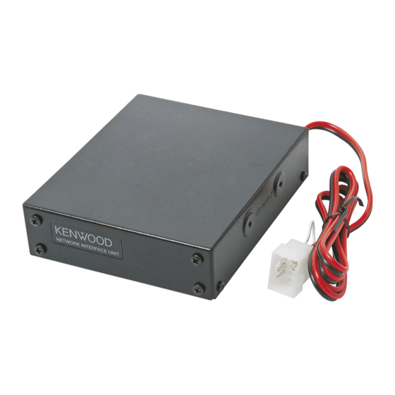
NETWORK INTERFACE UNIT
KTI-3
SERVICE MANUAL
Badge
(B43-1652-04)
Lead wire with connector
(E37-1526-15)
GENERAL ................................................................ 2
REALIGNMENT ....................................................... 3
OPERATING FEATURES ........................................... 4
DISASSEMBLY FOR REPAIR .................................... 4
CIRCUIT DESCRIPTION .......................................... 5
COMPONENTS DESCRIPTION .............................. 5
PARTS LIST ............................................................. 6
EXPLODED VIEW .................................................... 9
This product complies with the RoHS directive for the European market.
NETWORK INTERFACE UNIT
N SYNC
DC IN
PWR STATUS
13.6V
CONTENTS
AUX
LAN
Lead wire with connector
Chassis
(E37-1527-05)
(A10-4145-02)
PACKING .................................................................... 10
TERMINAL FUNCTION .......................................... 11
PC BOARD
INTERFACE UNIT (X46-3370-20) ................... 14
SCHEMATIC DIAGRAM ........................................ 18
BLOCK DIAGRAM ................................................. 24
SPECIFICATIONS .................................................. 26
© 2010-8 PRINTED IN JAPAN
B51-8928-00 ( Y ) 412
Metallic cabinet
(A01-2229-02)
This product uses Lead Free solder.
Advertisement
Table of Contents

Summary of Contents for Kenwood KTI-3
-
Page 1: Table Of Contents
NETWORK INTERFACE UNIT KTI-3 SERVICE MANUAL © 2010-8 PRINTED IN JAPAN B51-8928-00 ( Y ) 412 Badge NETWORK INTERFACE UNIT (B43-1652-04) N SYNC DC IN PWR STATUS Metallic cabinet (A01-2229-02) 13.6V Lead wire with connector Lead wire with connector Chassis... -
Page 2: General
Kenwood reserves the right to make changes to any products herein at any time for improvement purposes. GENERAL Service Manual parts numbers for equipment relative to the KTI-3 Model Parts Number Remarks... -
Page 3: Realignment
Conditions of the NXR-710/810 installing the firmware in User mode the KTI-3. • When the firmware besides the firmware of the KTI-3 that the NXR-710/810 stores is installed in the KTI-3 or no Firmware programming mode firmware is written in the KTI-3. -
Page 4: Operating Features
KTI-3 OPERATING FEATURES Rear Panel 1. Indicators (PWR STATUS) Indicators (LAN) Mode Indicator Color Meaning N SYNC Green Lights while the power is ON. DC IN User mode Lights when used as a Host PWR STATUS STATUS Orange repeater. 13.6V... -
Page 5: Circuit Description
KTI-3 CIRCUIT DESCRIPTION 1. MCU circuit 4. LAN interface circuit The MCU (IC10) 32bit microcontroller includes a 98kbit This circuit consists of IC6 and J20. chip SRAM. This interface circuit corresponds to 100Base-TX and 10Base-T. 2. Memory circuit The flash memory has a capacity of 8Mbit (IC11) and 32Mbit (IC12). -
Page 6: Parts List
KTI-3 PARTS LIST ◆ New Parts. indicates safety critical components. L : Scandinavia K : USA P : Canada Parts without Parts No. are not supplied. Y : PX (Far East, Hawaii) T : England E : Europe Les articles non mentionnes dans le Parts No. ne sont pas fournis. - Page 7 KTI-3 PARTS LIST INTERFACE UNIT (X46-3370-20) Ref. No. Address New Desti- Ref. No. Address New Desti- Parts No. Description Parts No. Description parts nation parts nation C109 CK73HB1A104K CHIP C 0.10UF L92-0639-05 CHIP FERRITE C110 CC73HCH1H470J CHIP C 47PF L15 -17...
- Page 8 KTI-3 PARTS LIST INTERFACE UNIT (X46-3370-20) Ref. No. Address New Desti- Ref. No. Address New Desti- Parts No. Description Parts No. Description parts nation parts nation RK73HB1J103J CHIP R 1/16W LT3685EMSE ANALOGUE IC RK73HB1J473J CHIP R 1/16W TC7WT125FUF MOS-IC RK73HB1J103J...
-
Page 9: Exploded View
KTI-3 EXPLODED VIEW Note: When replacing the LED, bend the leg of the LED at 4.0 mm (0.16 inches). D11, D12 4.0 mm (0.16 inches) CN10 Interface unit (X46) A : N35-2605-43 B : N35-3005-43 C : N87-2606-48 Parts with the exploded numbers larger than 700 are not supplied. -
Page 10: Packing
KTI-3 PACKING 706 Item carton box 705 Protection bag 8 Modular cable (E30-7717-05) 13 Cushion (G13-2338-04) 14 Cushion x4 (G13-2339-04) 6 Instruction manual (B62-2283-10) 704 Protection bag 703 Packing fixture Parts with the exploded numbers larger than 700 are not supplied. -
Page 11: Terminal Function
KTI-3 TERMINAL FUNCTION Interface unit (X46-3370-20) Pin No. Name Function CN10 (To DC power supply connector cable) Ground Power supply input (+B) CN11 (To AUX connector) Not used AUX_O2 Not used AGND Ground (analog) No connection Not used AUX_I2 Not used... -
Page 12: Specifications
KTI-3 TERMINAL FUNCTION DC power supply connector P i n Description / Pin Name I/O Signal Type Modification Specification Unit Remarks port Type 10.8 13.6 15.6 Power Power Supply Jumper Short This pin is connected to Jumper to 12pin SPI (NXR-710/810). - Page 13 KTI-3 TERMINAL FUNCTION N_SYNC P i n Signal Description / port Pin Name Modification Specification Unit Remarks Type Type [Input] conform to RS-485 VID=VA-VB Vcc=5±4% RS-485 Differential N_SYNC2_A Digital -0.2 Signal #2 A [Output](No load) VOD=|VA-VB| [Input] conform to RS-485 VID=VA-VB Vcc=5±4%...
- Page 14 KTI-3 General Standard Input Voltage ..................13.6V DC negative ground (Supplied from NXR-710/810) Current Drain ..................... 200mA Max Temperature Range ................... –30°C ~ +60°C (–22°F ~ +140°F) Dimensions (W x H x D, Dimensions not including protrusions) ......106 (4.17) x 32 (1.26) x 125 (4.92) mm (inch)
- Page 15 Suite 2504, 25/F, Tower 2, Nina Tower, No. 8 Yeung Uk Road, Bp 58416 Villepinte, 95944 Roissy Ch De Gaulle Cedex Tsuen Wan, New Territories, Hong Kong 1 Ang Mo Kio Street 63, Singapore 569110 KENWOOD House, Dwight Road, Watford, Herts., WD18 9EB United Kingdom...


Need help?
Do you have a question about the KTI-3 and is the answer not in the manual?
Questions and answers