Hydac FCU 1310 Operating And Maintenance Instructions Manual
Fluidcontrol unit
Hide thumbs
Also See for FCU 1310:
- Operating and maintenance instructions manual (148 pages) ,
- Operating instructions manual (100 pages)
Table of Contents

Subscribe to Our Youtube Channel
Related Manuals for Hydac FCU 1310


Summary of Contents for Hydac FCU 1310
- Page 1 FCU 1310 FluidControl Unit Operating and maintenance instructions English (translation of original instructions) Valid from firmware version V 3.00 up Valid from series no. (S/N) 0002S01831K0001000 Keep for future reference. Document No.: 3371346f...
-
Page 2: Imprint
Court of Registration: Saarbrücken, HRB 17216 Executive director: Mathias Dieter, Dipl.Kfm. Wolfgang Haering Documentation representative Mr. Günter Harge c/o HYDAC International GmbH, Industriegebiet, 66280 Sulzbach / Saar Phone: +49 6897 509 1511 Fax: +49 6897 509 1394 E-mail: guenter.harge@hydac.com © HYDAC FILTER SYSTEMS GMBH All rights reserved. -
Page 3: Table Of Contents
Content Content Imprint ......................2 Documentation representative ..............2 Content ......................3 What's New — Changes to the manual ............7 Preface ......................8 Technical Support ..................8 Modifications to the Product ................ 8 Warranty ...................... 8 Using the documentation ................9 Safety information .................. - Page 4 Content Selecting the measurement location ............38 Select the measurement method according to the pressure involved ..................... 39 Measuring up to max. 45 bar / 650 psi............40 Measuring in the range 5 to 345 bar / 217 to 5000 psi ......43 Measuring from unpressurized containers ..........
- Page 5 Content Pins used on the DATA interface (HYDAC Sensor Interface – HSI) ......................69 Connecting FCU with HMG 510 / HMG 3000 / 4000 ......70 Reading out USB interface measured values ..........71 Copying measurements onto a USB data stick ........71 - Data transmission failed ........
- Page 6 Content Brazil ....................112 Factory default settings................112 Overview / Definition of the cleanliness classes ........113 Cleanliness class acc. to ISO 4406:1999 ..........113 ISO 4406 overview table ..............114 Difference between ISO4406:1987 and ISO4406:1999 ....... 115 Cleanliness class acc. to SAE AS 4059 ..........116 SAE AS 4059 overview table ............
-
Page 7: What's New - Changes To The Manual
What's New — Changes to the manual What's New — Changes to the manual The index is featured on the cover sheet of the operating and maintenance manual and in the lower left corner of each page after the part number. Index "a"... -
Page 8: Preface
After modification or repair work that affects the safety of the product has been carried out on components, the product may not be returned to operation until it has been checked and released by a HYDAC technician. Please notify us immediately of any modifications made to the product whether by you or a third party. -
Page 9: Using The Documentation
Preface Using the documentation Note that the method described for locating specific information does not release you from your responsibility of carefully reading all these instructions prior to starting the unit up for the first time and at regular intervals in the future. What do I want to know? I determine which topic I am looking for. -
Page 10: Safety Information
Safety information Safety information The product was built according to the statutory provisions valid at the time of delivery and satisfies current safety requirements. Any residual hazards are indicated by safety information and instructions and are described in the operating instructions. Observe all safety and warning instructions attached to the product. -
Page 11: Signal Words And Their Meaning In The Safety Information And Instructions
Safety information Risk of burns due to hot surfaces Signal words and their meaning in the safety information and instructions In these instructions you will find the following signal words: DANGER DANGER – The signal word indicates a hazardous situation with a high level of risk, which, if not avoided, will result lethal or serious injury. -
Page 12: Structure Of The Safety Information And Instructions
Safety information Structure of the safety information and instructions All warning instructions in this manual are highlighted with pictograms and signal words. The pictogram and the signal word indicate the severity of the danger. Warning instructions listed before an activity are laid out as follows: SIGNAL WORD Type and source of danger HAZARD SYMBOL... -
Page 13: Proper/Designated Use
HYDAC is not responsible. HYDAC is not responsible for the installation, integration, selection of interfaces to / into your system nor for the use or functionality of your system. -
Page 14: Periodic Intermittent Duty - Operating Mode S3, (As Per Din En 60034-1 / Din Vde 0530, Part 1)
Safety information NOTICE Connection to 24 V DC on-board networks without load dump The FCU will be destroyed. Use the FCU only on 24 V DC on-board networks which have a central ► "Load Dump" fuse. Before connecting, be sure to check that a load dump is installed with ►... -
Page 15: Improper Use Or Use Deviating From Intended Use
► Any use extending beyond this or deviating therefrom shall not be considered intended use. HYDAC FILTER SYSTEMS GmbH will assume no liability for any damage resulting from such use. The user alone, shall assume any and all associated risk. -
Page 16: Qualifications Of Personnel / Target Group
Maintenance, • Product-specific knowledge Decommissioning, Disassembly Service staff • Very detailed product-specific (only with knowledge authorized HYDAC Service) Disposal Specialist • Proper and environmentally- personnel friendly disposal of materials and substances • Decontamination of contaminants • Knowledge about reuse... -
Page 17: Wear Personal Protection Equipment
Safety information Wear personal protection equipment Observe the information relating to personal protection equipment in the safety data sheet of the operations fluid. • Wear eye protection. • Wear gloves. Stoppage in an emergency (EMERGENCY STOP) In the event of an emergency, disconnect the FCU from the power supply and from the hydraulic system. -
Page 18: Fcuopening/Closing
FCUOpening/Closing FCUOpening/Closing Open the FCU by releasing both clips. Close the FCU using both clips. Make sure that these audibly snap into place. en(us) FCU1310 Page 18 / 124 BeWa FCU1310 V300 3371346f en-us 2017-01-27.docx 2017-01-27... -
Page 19: Fcutransporting
FCUtransporting FCUtransporting Transport the FCU only when it is in closed position; carry it flat or by the handle. en(us) FCU1310 Page 19 / 124 BeWa FCU1310 V300 3371346f en-us 2017-01-27.docx 2017-01-27... -
Page 20: Fcustoring
FCUstoring FCUstoring Drain and rinse the FCU completely before putting it into storage. See page 88 in the "FCU flushing" chapter for details on rinsing the FCU. Observe permissible conditions required for storage on page 108 in the "Technical Data" chapter. Store the FCU closed and in a horizontal position in a dry, clean place. -
Page 21: Decoding The Model Code Label
Decoding the model code label Decoding the model code label For identification details of the FluidControl Unit, see the model code label. The type label displays the product ID and important technical data. Item -> Description -> Type label for FCU ->... - Page 22 Decoding the model code label The following information can be found on the name plate of the product: -> Description Model -> Model code; for details, see page 110. Date -> Production year/week -> Part number -> Serial no. Flow rate ->...
-
Page 23: Checking The Scope Of Delivery
Checking the scope of delivery Checking the scope of delivery The FluidControl Unit comes factory-assembled. Before commissioning the FCU, check the contents of the consignment to make sure everything is present. The following items are supplied: Item Description FluidControl Unit FCU, including attachable bag for cables and hoses Power supply, primary: 90-240 V AC / secondary: 24 V DC / 5 A... -
Page 24: What Can The Product Do
What can the product do? What can the product do? The FluidControl Unit FCU is a portable service unit for taking short-term measurements of the solid particle contamination, temperature und % saturation level in hydraulic systems. Knowledge on the level and amount of contamination allows you to check and document quality standards and introduce the required optimization measures. -
Page 25: Counting Contaminant Particles
What can the product do? Counting contaminant particles The measuring principle of the light blockade procedure is shown in simplified form in the following sketch. The light source transmits monochromatic light through the flow of oil to a photo detector, which produces a particular electrical signal. If a particle gets between the light source and the photo detector, then a shadow will be cast on the photo detector. - Page 26 What can the product do? Each of the signal peaks corresponds to the shadow cast by one particle. The signal height or amplitude reflects the particle size. Thresholds are used to classify the particle sizes >2, >5, >15, >25 µm or >4, >6, >14, >21 µm Time en(us) FCU1310...
-
Page 27: How The Product Works
What can the product do? How the product works From the oil source (either a pressure port or a bottle sample), a continuous oil flow is established through the port (1) INLET by an electrically controlled gear pump (3). A suction strainer (2) protects the pump from coarse contamination. The oil current to be analyzed flows through an optical ContaminationSensor (6). -
Page 28: Overview Of Control Panel/Operating Elements
What can the product do? Overview of control panel/operating elements Item Designation Display of “ISO, SAE/NAS, Flow, Drive” with keypad Display of the percentage "water saturation" "Fluid temperature" display ON / OFF switch for the internal pump Supply voltage 24 V DC Data interface (DATA) Connection OUTLET Connection INLET, type 1604... -
Page 29: Dimensions
What can the product do? Dimensions The FCU has the following dimensions. All dimensions in mm. en(us) FCU1310 Page 29 / 124 BeWa FCU1310 V300 3371346f en-us 2017-01-27.docx 2017-01-27... -
Page 30: Hydraulic Diagram
What can the product do? Hydraulic diagram Item Designation INLET, gauge port type 1604 Suction screen, 400 µm Gear pump Electric motor Pressure relief valve ContaminationSensor unit Counter balance valve AquaSensor AS1000 OUTLET, DN7 Quick coupling nipple en(us) FCU1310 Page 30 / 124 BeWa FCU1310 V300 3371346f en-us 2017-01-27.docx 2017-01-27... -
Page 31: Using The Batterypack (Accessory)
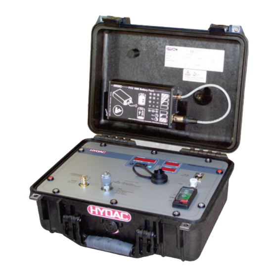
Using the BatteryPack (accessory) Using the BatteryPack (accessory) With the BatteryPack, which is available as an accessory, you can make the FCU independent of the electrical supply network. For technical details on the BatteryPack, see its instruction brochure. With the locking pin (2), the BatteryPack (1) is held securely in the mounting rails (3) during transport. - Page 32 Using the BatteryPack (accessory) To fit the BatteryPack into its holder, proceed as follows: 1. Remove the connector (A) from the socket on the BatteryPack. 2. Slide the BatteryPack into the mounting rails from above. en(us) FCU1310 Page 32 / 124 BeWa FCU1310 V300 3371346f en-us 2017-01-27.docx 2017-01-27...
- Page 33 Using the BatteryPack (accessory) 3. Pull the locking pin (1). Slide the BatteryPack down until it touches the lower stop in the guide rails (2). Release the locking pin (3). A spring will return the locking pin to its original position, thus securing the BatteryPack.
- Page 34 Using the BatteryPack (accessory) To remove it, proceed as follows: 1. Remove the connector from the socket. 2. Pull the locking pin out to release the BatteryPack (1). Slide the BatteryPack upwards (2). en(us) FCU1310 Page 34 / 124 BeWa FCU1310 V300 3371346f en-us 2017-01-27.docx 2017-01-27...
- Page 35 Using the BatteryPack (accessory) 3. Pull the BatteryPack up and out of the mounting rails. Then insert the connector back into the socket on the BatteryPack. en(us) FCU1310 Page 35 / 124 BeWa FCU1310 V300 3371346f en-us 2017-01-27.docx 2017-01-27...
-
Page 36: Preparing The Fcu For Measurement
(included in the FCU delivery). Connect the power plug of the adaptor into the power supply. After the unit is plugged in, HYDAC FCU 1### appears in moving letters, followed by the firmware version, which appears for 2 seconds. -
Page 37: Plug In/Detach Return Hose
Preparing the FCU for measurement Plug in/Detach return hose NOTICE Closed or blocked outlet at the connection OUTLET The FCU can be damaged. Never seal the OUTLET connection OUTLET. ► Put the free end of the OUTLET return hose into an unpressurized ►... -
Page 38: Selecting The Measurement Location
Preparing the FCU for measurement Selecting the measurement location Select the measurement location so that the sample measured comes from a turbulent location, with a good flow. For example on a pipe bend. This ensures that a typical sample is analyzed. If the FCU is installed near the measurement point, avoid delayed ... -
Page 39: Select The Measurement Method According To The Pressure Involved
Preparing the FCU for measurement Select the measurement method according to the pressure involved After you have selected the measurement location according to the above- mentioned criteria, determine what the operating pressure is at that location. Select the measurement method that is suitable for the pressure at the measurement point: Pressure at the Measurement method... -
Page 40: Measuring Up To Max. 45 Bar / 650 Psi
Preparing the FCU for measurement Measuring up to max. 45 bar / 650 psi WARNING Hydraulic systems are under pressure Danger of bodily injury The system must be depressurized before ► performing any work on the product. If the pressurized connection is connected to ►... - Page 41 Preparing the FCU for measurement Required hoses: Return hose High-pressure hose Make sure that the following sequence is observed: 1. Go through the steps in chapter "FCU für die Messung vorbereiten“ on pages 36 to 39. 2. Check the pressure at the measurement location.
- Page 42 Preparing the FCU for measurement 3. Connect the inlet pressure hose (black) to the port INLET of the FCU (1). Screw the measurement coupling clockwise (2) onto the connection and screw it finger tight. 4. Connect the other end of the INLET pressure hose to the measurement point of the system.
-
Page 43: Measuring In The Range 5 To 345 Bar / 217 To 5000 Psi
Preparing the FCU for measurement Measuring in the range 5 to 345 bar / 217 to 5000 psi WARNING Hydraulic systems are under pressure Danger of bodily injury The system must be depressurized before ► performing any work on the product. If the pressurized connection is connected to ►... - Page 44 Preparing the FCU for measurement Required hoses / adapters: Return hose High-pressure adapter High-pressure hose Make sure that the following sequence is observed: 1. Go through the steps in chapter "Preparing the FCU for measurement“ on pages 36 to 39. en(us) FCU1310 Page 44 / 124...
- Page 45 Preparing the FCU for measurement 2. Check the pressure at the measurement location. The pressure there must be in the range from 15 - 345 bar / 217 - 5000 psi. If the pressure is greater than 345 bar / 5000 psi, please cancel the process.
- Page 46 Preparing the FCU for measurement 6. Switch on the internal pump. 7. This completes the hydraulic installation. 8. The FCU will start with the measurement. en(us) FCU1310 Page 46 / 124 BeWa FCU1310 V300 3371346f en-us 2017-01-27.docx 2017-01-27...
-
Page 47: Measuring From Unpressurized Containers
Preparing the FCU for measurement Measuring from unpressurized containers Required hoses: Return hose Suction hose To guarantee valid and direct measurements, prime the FCU. To do this, draw in ≈ 120 ml fluid via the inlet hose in order to completely fill the hydraulic circuit and the inlet hose. - Page 48 Preparing the FCU for measurement Make sure that the following sequence is observed: 1. Go through the steps in chapter "Preparing the FCU for measurement“ on pages 36 to 39. 2. Connect the suction hose (transparent) to the INLET of the FCU.
-
Page 49: Fcuoperating
FCUoperating FCUoperating When the FCU is powered up, it is ready for use and the parameters can be set. In the following, the individual controls and their use are described. Display and keypad elements Item Designation STATUS Status display (see page 99 for details). Display Consists of a 6-digit display and shows the selected measured values. - Page 50 FCUoperating The keyboard consists of six buttons. These buttons are used to operate the FCU and to navigate through the menus (hierarchically structured). Keyboard Description one level down confirm changed value (lowest level) confirm when changes are to be saved or canceled (top level) one level up No value change...
-
Page 51: Clicking Through The Display
FCUoperating Clicking through the display According to the calibration type ( ) in the Power up menu, the following displays can be clicked through with the buttons. - Display Display Description 3-digit ISO code SAE Class A SAE Class B SAE Class C SAE Class D SAE Max. -
Page 52: Display
FCUoperating - Display Display Description 3-digit ISO code NAS 2-5 µm channel NAS 5-15 µm channel NAS 15-25 µm channel NAS > 25 µm channel NAS Max. Flow status LED current in % en(us) FCU1310 Page 52 / 124 BeWa FCU1310 V300 3371346f en-us 2017-01-27.docx 2017-01-27... -
Page 53: Displaying Measured Variables
FCUoperating Displaying measured variables The measurements provide you with information about the purity of the oil in the system concerned. The measurement variables are calibrated. They indicate a measured value with an accuracy of +/- 1/2 ISO codes. " " measured variable Display Description The measurement value is updated... -
Page 54: Display Service Variables
FCUoperating The integrated AquaSensor continuously measures the fluid temperature. The output as Celsius °C or Fahrenheit °F can be selected under TP.UNIT on page 65. Example: Temperature = 37.8 °C Display service variables These values give you information about the determined flow and the light source power. -
Page 55: Select Operating Level / Configuration Menu
Select operating level / configuration menu Select operating level / configuration menu The FCU has the following two operating levels / configuration menus: Menus Description Details are on page Menu The basic settings for the FCU Settings for the recording and storing of Measuring Menu the measurements and naming the measurement points. -
Page 56: Operate / Set Up Menu
Select operating level / configuration menu Operate / Set up menu In the menu, the basic settings for the operation of the FCU are made. Selection To do Press any button and hold it down while Start menu switching on the supply voltage. Exit the menu without Scroll to and press... -
Page 57: Setting Date/Time
Select operating level / configuration menu – Setting date/time In this option you can set or alter the system date / time. If the date has never been set, or if the buffer battery is flat , the system date will be and the time will be The date format is:... -
Page 58: Delete Memory
Select operating level / configuration menu - Delete memory With , you permanently delete all of the measurement records in the internal memory. Before deletion, back up all of the measurement records on the USB memory stick. Push the following buttons to: Confirm deletion Cancel and back - Set measuring time... -
Page 59: Select Calibration Type
Select operating level / configuration menu – Select calibration type Under , select the desired calibration type, either calibration type is based on ISO4406:1999 / SAE. calibration type is based on ISO4406:1987 / NAS. Use the following buttons: To change between the types of calibration To confirm the... -
Page 60: Cancel
Select operating level / configuration menu - Cancel discards all changes and exits the menu. Use the following buttons: To change digit To confirm the change Cancel and back – Save data With , you save all changes and exit the menu. -
Page 61: Operating/Setting Measuring Menu
Select operating level / configuration menu Operating/Setting measuring menu The Measuring Menu allows you to change settings during operation. Selection To do Start the measuring menu Press the button Scroll to and press Exit the measuring menu wait for 30 seconds with no further action without saving and the FCU will automatically switch to display mode. -
Page 62: Record Measurements
Select operating level / configuration menu – Record measurements With this option you define under which of the 20 available measurement points the records should be saved. Use the following buttons: To change digit To confirm the change Cancel and back Use the following buttons: To change digit To confirm the... -
Page 63: Display Free Memory
Select operating level / configuration menu Select to create a new file in the internal FCU memory under the new measurement point. Press and the display will jump to Confirm again by pressing Use the following buttons: Change the selection To confirm the change Cancel and back... -
Page 64: Change Name Of Measurement Point
Select operating level / configuration menu – Change name of measurement point Under you can modify the designation of the measurement point to meet your wishes. You have a maximum of 6 characters available for the measurement point designation. Example: TEST01, EXCAVATOR, CRANE, etc. Use the following buttons: Change to the next option in the menu... -
Page 65: Set Temperature Unit
Select operating level / configuration menu The following characters will appear, when the button is pressed, wrapping around at the end. The empty space is located between 9 and A and can be adjusted only from the 6th position to the left. This means that you can enter a name with less than 6 characters. -
Page 66: Cancel
Select operating level / configuration menu - Cancel discards all changes and exits the Measuring menu. Use the following buttons: Change to the next option in the menu Confirm Cancel and back – Save data With , you save all changes and exit the Measuring menu. Use the following buttons: Change to the next option in the menu... -
Page 67: Performing Measurements
Performing measurements Performing measurements Check all the hydraulic and electrical connections to the FCU. Now press the green "Pump ON" switch. The pump feeds oil to be analyzed through the FCU After the set measurement duration, the result will be shown on the display, and the status LED will light up green, steadily. -
Page 68: Reading Internal Measurement Memory
Reading internal measurement memory Reading internal measurement memory All measurements are kept in internal memory, with a reference to the measurement point, until deliberately deleted by means of the function. The internal memory has a capacity of > 30000 lines = measurement records. -
Page 69: Read Out Measured Values Via Data Interface
Connecting FCU with a CSI-B-2 kit The FCU can be connected to a PC using the CSI-B-2 kit. Pins used on the DATA interface (HYDAC Sensor Interface – HSI) The HSI interface has a 5-pin M12x1 connection plug in accordance with DIN VDE 0627. -
Page 70: Connecting Fcu With Hmg 510 / Hmg 3000 / 4000
Reading internal measurement memory Connecting FCU with HMG 510 / HMG 3000 / 4000 The following portable data recorders (HMG) can be used to give a readout of the FCU via the DATA interface: - HMG 510 (with firmware version 2, release 15 or higher) - HMG 3000 (with firmware version 2, release 1 or higher) For further details, see the operating instructions for the HMG. -
Page 71: Reading Out Usb Interface Measured Values
FCU communicates directly with the microprocessor. This means that communication errors cannot be corrected in software, like, for example, on a PC with an operating system. We recommend using the HYDAC USB memory stick, which we successfully tested for many PC/operating system combinations. - Page 72 Reading internal measurement memory 2. Insert the USB memory stick into the socket. Note that the stick only fits one way around. It must be easy to insert the USB stick into the socket. 3. After inserting the USB memory stick, the FCU will detect it and immediately start copying the measurement data.
- Page 73 Reading internal measurement memory 7. Now remove the USB memory stick from the socket by gently pulling it upwards. 8. Close the cover to the USB connection (1) by turning it clockwise (2). en(us) FCU1310 Page 73 / 124 BeWa FCU1310 V300 3371346f en-us 2017-01-27.docx 2017-01-27...
-
Page 74: Data Transmission Failed
If the error recurs -> proceed to Step 10. ->b. If the error does not recur -> proceed to Step 11. Contact the HYDAC Service department. The download has been successfully completed en(us) FCU1310 Page 74 / 124 BeWa FCU1310 V300 3371346f en-us 2017-01-27.docx... -
Page 75: Reading Out Measured Values Via Bluetooth Interface
Reading internal measurement memory Reading out measured values via Bluetooth interface The FCU Bluetooth interface is based on Bluetooth Version 1.2, Class 3. This means that: Bluetooth Version 1.2: is less sensitive to static disturbances (e.g. WLAN), the maximum data transfer rate is 732.2 kBit/s Class 3: a maximum performance of 1 mW or 0 dBm, reaches a maximum of 10 m... -
Page 76: Installing The Bluetooth Usb Adaptor
Customer. Connecting/Linking the FCU via Bluetooth The FCU is registered in the Bluetooth environment as: FCU 1310. If the connection to the FCU is established via Bluetooth, the measured values can be read by FluMoS, for example. The FCU protocol is used to communicate with the HSI. -
Page 77: Evaluating Measurement Records
Evaluating measurement records Evaluating measurement records The measurement records read out of the FCU and stored on the USB memory stick are defined as follows: Measurement record directories according to measurement point If measurements are stored under a measurement point , the FCU automatically produces a directory for this measurement point and puts the measurement records there. -
Page 78: Opening Measurement Reports
Evaluating measurement records Opening measurement reports The file containing the measurement reports has a file extension e.g. ".026". This extension may not be recognized by your PC. This means that you must tell your PC that, in future, you would like to open this file with MS Excel. Open the file with MS excel by right-clicking on it and then selecting "Open". - Page 79 Serious fault => The sensor or equipment is faulty. Contact the HYDAC Service department. See page 99 for more information about the individual faults. The values for SAE A-D or NAS 2-25 as well as the temperature units are defined by the FCU settings.
-
Page 80: The Measurements Are Shown As Dates
Evaluating measurement records The measurements are shown as dates On opening the file, all decimal numbers will be shown as dates. To resolve this, proceed as follows: 1. Start Excel. 2. From the menu bar, select the "Open" command. Open the measurement file. 3. - Page 81 Evaluating measurement records OK button. 7. Click on the "Finish" button, to Text conversion assistant - step 3 of 3 Data format of the columns complete the import of the Standard Text measurement data. Date Do not import column Other Preview of the marked data Cancel <...
-
Page 82: Evaluating/Reading Measurement Reports With Flumos
FluMoS light is available as freeware on the CD included in the delivery or as a download. You will find the link for the download on our homepage at www.hydac.com. You can order FluMoS professional as a fee- based accessory. -
Page 83: Preparing The Fcu For Transport
Preparing the FCU for transport Preparing the FCU for transport CAUTION Hot fluid at the connection Danger of burns Let the FCU and the hoses cool down. ► To prepare the FCU for transport, observe the following sequence: Use the switch to turn the internal pump off. - Page 84 Preparing the FCU for transport Close the USB socket with the corresponding cover. First undo the end of the high- pressure INLET hose that is at the measurement point of the hydraulic system. Remove the hose by turning counterclockwise from the INLET connection of the FCU.
- Page 85 Preparing the FCU for transport Undo the quick-action coupling of the return hose by lifting the outer ring. Empty the hose into an unpressurized container. To let air into the hose, open it by using a thin object to press in the check valve on the quick-action coupling.
- Page 86 Preparing the FCU for transport Release the catch (1) and then pull the socket out of the connector (2). Close the FCU using both clips. Make sure that these audibly snap into place. Stow the hose and the power supply in the bag.
-
Page 87: Performing Maintenance
Performing maintenance Performing maintenance WARNING Hydraulic systems are under pressure Danger of bodily injury Before working on the product, remove all ► hydraulic and electrical connections. At the latest, conduct the required configuration maintenance and inspection work every six months, otherwise, whenever an error message or malfunction makes it necessary. -
Page 88: Fcu Flushing
Performing maintenance FCU flushing NOTICE Impermissible flushing media The FCU will be destroyed Flush the FCU with low-viscosity mineral oils or mineral oil-based ► raffinates (e.g. diesel) whose flash point is higher than 55°C / 131°F. Never flush the FCU with universal thinners or other degreasing fluids. ►... - Page 89 Performing maintenance Flush the FCU as described below: Put approx. 0.5 liters of filtered oil into a clean container. Connect the return hose to the FCU and put the free end into a container for the used fluid. en(us) FCU1310 Page 89 / 124 BeWa FCU1310 V300 3371346f en-us 2017-01-27.docx 2017-01-27...
- Page 90 Performing maintenance Attach the suction hose onto the INLET connection of the FCU. Put the free end of the suction hose into the container with the filtered oil. Use the switch on the FCU to turn its pump on. en(us) FCU1310 Page 90 / 124 BeWa FCU1310 V300 3371346f en-us 2017-01-27.docx...
- Page 91 Performing maintenance Cleanliness values will be displayed during the flushing procedure. These measurements are not correct, but should decrease during the flushing procedure. Once the 0.5 liters have been sucked up, switch off the pump. The FCU flushing procedure is complete.
-
Page 92: Clean The Suction Strainer
Performing maintenance Clean the suction strainer NOTICE Operation without a suction strainer The FCU pump can be damaged Never use the FCU without a suction screen. ► Clean the suction screen regularly. ► The suction screen is fitted under the measurement point union at the INLET connection and protects the pump from contamination by coarse particles. - Page 93 Performing maintenance 4. Put a finger in the opening ... 5..and pull out the suction screen upwards. en(us) FCU1310 Page 93 / 124 BeWa FCU1310 V300 3371346f en-us 2017-01-27.docx 2017-01-27...
- Page 94 Performing maintenance 6. Clean the suction screen by blowing it out with compressed air. Before reassembly, check that the sealing ring for the connector is undamaged. Replace it if necessary. Before screwing it in place, wet the sealing ring (C) with some hydraulic fluid.
- Page 95 Performing maintenance 8. Manually screw the INLET connector in clockwise. 9. Using a INLET 19 mm wrench, tighten the connector, turning it clockwise. Note the maximum torque of 25 Nm. 10. Replacing/cleaning the suction screen is complete. en(us) FCU1310 Page 95 / 124 BeWa FCU1310 V300 3371346f en-us 2017-01-27.docx 2017-01-27...
-
Page 96: Checking The High Pressure Adapter
Performing maintenance Checking the high pressure adapter In the high pressure adapter there is a 400 µm strainer to protect the flow control valve. Clean this strainer at least every six months, or more frequently if heavy soiling makes it necessary. The flow rate through the high-pressure adapter is limited to approx. -
Page 97: Cleaning / Changing The Strainer In The High Pressure Adapter
Performing maintenance Cleaning / changing the strainer in the high pressure adapter NOTICE Operation without a strainer The FCU pump can be damaged Never use the high-pressure adapter without a strainer. ► Clean the suction strainer regularly ► The strainer (B) in the high-pressure adapter must be cleaned regularly. Remove the measurement coupling (A) from the threaded joint (D) with a 22 mm open-jaw wrench, anticlockwise. -
Page 98: Cleaning / Changing The Strainer In The High Pressure Adapter
Performing maintenance Cleaning / changing the strainer in the high pressure adapter NOTICE Wrong installation of the flow control valve Flow control valve is not working Pay attention to the direction of flow when installing the flow control ► valve. The flow control valve regulates the flow to approx. -
Page 99: Identifying And Interpreting Status/Error Messages
=> Sensor / equipment status is "fault". Restart the FCU by switching it off and then on again. Serious fault => The sensor or equipment is faulty. Contact the HYDAC Service department. LED Display STATUS To do Error flashing code... - Page 100 Switch the FCU ContaminationSens off and then on or is attached or the again. communication is If the fault recurs, defective. contact HYDAC Service department. ContaminationSens Switch the FCU or is causing a off. moderate fault. If the fault recurs,...
- Page 101 Error flashing code code No AquaSensor is Switch the FCU connected. off and then on again. If the fault recurs, contact HYDAC Service department. AquaSensor is Switch the FCU causing a moderate off and then on fault. again. If the fault recurs,...
- Page 102 Identifying and interpreting status/error messages LED Display Status / Error flashing code To do code The FCU has a major fault. / Contact the HYDAC Service department. en(us) FCU1310 Page 102 / 124 BeWa FCU1310 V300 3371346f en-us 2017-01-27.docx 2017-01-27...
-
Page 103: Restarting/Resetting
Restarting/resetting Restarting/resetting To restart or reset the FCU, remove the power supply to the FCU for 10 seconds. To remove the connector To insert the connector Press the catch (1) on the connector Insert the connector into the socket and then pull (2) the connector out. until it audibly snaps in. -
Page 104: Locating Spare Parts
Locating spare parts Locating spare parts Part no. Description Image High pressure hose with screwed joint, for 349150 measurement point type 1620, color: black, L = 2 m Suction hose with open end, 3297276 color: clear-transparent, Length = 0.3 m Return hose, open end, transparent, length = 349151 278475 Suction strainer, 400 µm (for INLET port) -
Page 105: Selecting Accessories
Locating spare parts Part no. Description Image 6059933 Power adapter (without connector cable) Primary: 100-240 V AC Secondary: 24 V DC, 5A, Cable with 3-pin connector, Length = 1.6 m 6008448 Connection cable for power adaptor European plug, Length = 2 m 6008447 Connection cable for power adaptor plug for England (UK),... - Page 106 Locating spare parts Part no. Description Image 12V/24 V DC cable with 3306236 universal plug, including 8A fuse, Length = 10 m 12V/24 V DC cable with 3524138 universal plug, including 8A fuse, Length = 1 m Fuse 8 A for universal plug 6052824 (Ø...
-
Page 107: Checking The Measuring Accuracy
Recalibrate the FCU according to ISO 9000 standard. We recommend a recalibration of the FCU at least every 3 years. For calibration, contact one of the following HYDAC national subsidiaries, see "Finding Customer Service / Service stations" chapter on page 111. -
Page 108: Technical Data
Technical Data Technical Data ContaminationSensor Self diagnostics continuously with error indication via status LED and display Display LED, 6 / 4 / 4-digit, each with 17 segments Measured values for solid ISO code / SAE class / NAS class particle contamination Measured values for fluid -25 …... - Page 109 Technical Data ContaminationSensor Permissible viscosity range 10 … 350 mm²/s / 46 … 1622 Sus (for hydraulic oil up to ISO VG 68) Maximal suction height Suction hose DN4 open-end, color: clear-transparent, Length = 0.3 m High-pressure hose DN4 with screw connection for measurement point 1620, color: black, Length = 2 m Return hose...
-
Page 110: Appendix
Appendix Appendix Model Code 0 - 4 - U - AS - 1 Product FCU = FluidControl Unit Series = 1000 series, 4 particle size channels Contamination code = ISO4406:1987; NAS 1638 ISO4406:1999; SAE AS4059 (D) Housing = for portable use (plastic case with a bag) Fluids = based on mineral oil... -
Page 111: Finding Customer Service / Service Stations
66540 Neunkirchen-Heinitz Phone: +49 6897 509 883 Fax: +49 6897 509 324 E-mail: service@hydac.com HYDAC Technology Corporation, HYCON Division 2260 City Line Road USA-Bethlehem, PA 18017 P.O. Box 22050 USA-Lehigh Valley, PA 18002-2050 Phone: +1 610 266 01 00 Fax:... -
Page 112: Brazil
Appendix Brazil HYDAC TECNOLOGIA LTDA Estrada Fukutaro Yida, 225 CEP 09852-060 Cooperativa BR-São Bernardo do Campo – SÃO PAULO Phone: +55 11 4393 6600 Fax: +55 11 4393 6617 E-mail: hydac@hydac.com.br Homepage www.hydac.com.br Factory default settings If the "DFAULT" function is used for a reset, the following settings will be... -
Page 113: Overview / Definition Of The Cleanliness Classes
Appendix Overview / Definition of the cleanliness classes In the following chapter, you will find the definition of the cleanliness classes ISO 4406 / SAE AS 4059 and NAS 1638. Cleanliness class acc. to ISO 4406:1999 In ISO 4406:1999, particle counts are determined cumulatively, i.e. > 4 µm >6 µm and >14 µm (manually by filtering the fluid through an analysis... -
Page 114: Iso 4406 Overview Table
Appendix ISO 4406 overview table Allocation of particle counts to cleanliness codes: Number of particles / 100 ml Number of particles / 100 ml Class More than Up to (and Class More than Up to (and including) including) 16,000 32,000 32,000 64,000 64,000... -
Page 115: Difference Between Iso4406:1987 And Iso4406:1999
Appendix Difference between ISO4406:1987 and ISO4406:1999 "old" ISO 4406:1987 "new" ISO 4406:1999 Size ranges > 5 µm > 4 µm > 15 µm > 6 µm > 14 µm Dimension Longest dimension of Diameter of the determined a particle coextensive circle ISO 11171:1999 Test dust ACFTD - dust... -
Page 116: Cleanliness Class Acc. To Sae As 4059
Appendix Cleanliness class acc. to SAE AS 4059 Like ISO 4406, SAE describes AS 4059 particle concentrations in liquids. The analysis methods can be applied in the same manner as ISO 4406:1999. The SAE cleanliness classes are based on particle size, number and distribution. -
Page 117: Display Cleanliness Classes According To Sae Absolute Particle Count Larger Than A Defined Particle Size
Appendix Display cleanliness classes according to SAE Absolute particle count larger than a defined particle size Example: Cleanliness class to AS 4059:6 The maximum permissible particle count in the individual size ranges is bold- faced in the above table. Cleanliness class to AS 4059:6B Size B particles may not exceed the maximum number indicated for class 6. -
Page 118: Cleanliness Class Acc. To Nas 1638
Appendix Cleanliness class acc. to NAS 1638 Like ISO 4406, NAS 1638 describes particle concentrations in liquids. The analysis methods can be applied in the same manner as ISO 4406:1999. In contrast to ISO 4406, certain particle ranges are counted in NAS 1638 and attributed to key figures. -
Page 119: Ec Declaration Of Conformity
Documentation Representative: Mathias Dieter, Dipl.Kfm. Wolfgang Haering Mr. Günter Harge Registered seat of company: 66280 Sulzbach / Saar c/o HYDAC International GmbH, Industriegebiet, 66280 Sulzbach / Saar Court of Registration: Saarbrücken, HRB 17216 Phone: +49 6897 509 1511 Value added tax identification number : DE 815001609... - Page 120 Documentation Representative: Mathias Dieter, Dipl.Kfm. Wolfgang Haering Mr. Günter Harge Registered seat of company: 66280 Sulzbach / Saar c/o HYDAC International GmbH, Industriegebiet, 66280 Sulzbach / Saar Court of Registration: Saarbrücken, HRB 17216 Phone: +49 6897 509 1511 Value added tax identification number : DE 815001609...
-
Page 121: Explanation Of Terms And Abbreviations
See page 54 for details European Community European Union FluidControl Unit FLOW See page 54 for details FluMoS See page 82 for details HYDAC Measuring device HYDAC Sensor interface Inlet INLET Inlet Classification of the solid particle contamination, details see page 113 Light-emitting diode... -
Page 122: Index
Appendix Index FluMoS ......... 23, 24, 76, 82, 106, 122 accident prevention ............12 Accuracy ..............109 gear ................27 ambient temperature ..........22, 110 Gear pump ..............30 AquaSensor ......30, 53, 54, 100, 101, 111, 122 GND ................69 Assignment .............. - Page 123 Appendix Service variable ............. 49 setting ..............57, 58 Signal word ............. 11, 12 OFF ................28 signal words ............11, 12 operating 7, 8, 9, 10, 13, 14, 16, 23, 28, 39, 40, 43, 55, 67, Size ............115, 116, 117, 118 70, 71, 76, 109 Spare part ...............
- Page 124 HYDAC FILTER SYSTEMS GMBH Industriegebiet Postfach 1251 66280 Sulzbach/Saar 66273 Sulzbach/Saar Germany Germany Tel: +49 6897 509 01 Central Fax: +49 6897 509 9046 Technology Fax: +49 6897 509 577 Sales Department Internet: www.hydac.com E-mail: filtersystems@hydac.com...
Need help?
Do you have a question about the FCU 1310 and is the answer not in the manual?
Questions and answers