
Related Manuals for DPS NetGuardian 832A

Summary of Contents for DPS NetGuardian 832A
- Page 1 NetGuardian 832A/864A G5 ODOT USER MANUAL Visit our website at www.dpstelecom.com for the latest PDF manual and FAQs. November 22 , 2016 Firmware Version 5.3L D-UM-NETG5-12114...
-
Page 2: Revision History
DPS Telecom, except as required by United States copyright laws. The material in this manual is for information purposes and is subject to change without notice. DPS Telecom shall not be liable for errors contained herein or consequential damages in connection with the furnishing, performance, or use of this manual. -
Page 3: Table Of Contents
Contents Visit our w ebsite at w w w .dpstelecom .com for the latest PDF m anual and FAQs NetGuardian G5 Overview About This Manual Shipping List Port Allocation Optional Accessories Specifications Hardware Installation Tools Needed Mounting Power Connection LAN Connection Telco Connection Alarm and Control Relay Connections 6.6.1... - Page 4 6.10 Optional 66 Block Connector (864A) 6.11 Optional Hinged Wire-Wrap Back Panel 6.11.1 Lexan Wire-Wrap Cover 6.12 Optional Hinged Pluggable Back Panel 6.13 Optional Hinged Amphenol Back Panel 6.13.1 Alarm and Control Relay Connector Pinout Tables (KDA 864) 6.14 Controls 6.15 Bypassing Password LCD Display...
- Page 5 13.3.1.2 Monitoring Ping Targets 13.3.1.3 Monitoring and Operating Relays (Controls) 13.3.1.4 Monitoring Analogs 13.3.1.5 Monitoring System Alarms 13.3.1.6 Monitoring Data Port Activity 13.3.1.7 Monitoring the Accumulation Timer 13.3.1.8 Monitoring DSCP Devices 13.3.2 Viewing Live Target Pings 13.3.3 Proxy Menu 13.3.4 Event Logging 13.3.5 Backing Up NetGuardian Configuration Data via FTP...
-
Page 6: Netguardian G5 Overview
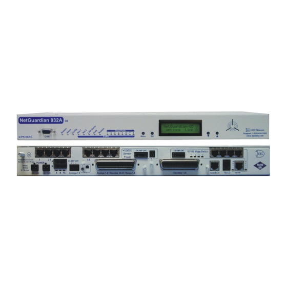
NetGuardian G5 Overview Fig. 1.1. The NetGuardian has all the tools you need to manage your remote site. The NetGuardian G5 — The Intelligent RTU for Complete Site Management The NetGuardian G5 is a RoHS 5/6-compliant, LAN-based, SNMP/DCPx remote telemetry unit. The NetGuardian has all the tools you need to manage your remote sites, including built-in alarm monitoring, paging and email capabilities that can eliminate the need for an alarm master. -
Page 7: About This Manual
While unpacking the NetGuardian, please make sure that all of the following items are included. If some parts are missing, or if you ever need to order new parts, please refer to the part numbers listed and call DPS Telecom at (800) 622-3314. - Page 8 NetGuardian G5 Resource CD DB9M-DB9F Download Cable 6 ft. (includes manuals, MIBs, and software) D-PR-045-10-A-04 Two Ethernet Cables 14 ft. Telephone Cable 6 ft. D-PR-923-10B-14 D-PR-045-10A-01 23" Rack Ears 19" Rack Ears D-CS-325-10A-01 D-CS-325-10A-00 Eight 3/8" Ear Screws (F) Four Standard Rack Screws (H) 2-000-60375-05 1-000-12500-06 Four Metric Rack Screws (G)
- Page 9 (Hardware kit containing a WAGO connector)
-
Page 10: Optional Items
Optional Items Two 3/4-Amp GMT Accessory Fuses (A) One Small Connector for Sensor Output 2-741-00250-00 2-820-00812-02 External Temperature Sensor 20 ft. External Temperature Sensor D-PR-991-10A-07 D-PK-SENSR-12037... -
Page 11: Port Allocation
NetGuardian Expansion (NetGuardian 832A/864A DX G5) D-PK-DX832/D-PK-DX864 The NetGuardian G5 expansions provide and additional 32 alarms for your NetGuardian 832A model or 64 points for your 864A, providing a total of 128 or 256 alarms with 3 expansion units. Each expansion comes standard with an additional 8 control relays and 8 analog inputs, and is available with an optional 8 port hub. - Page 12 Adding the NetGuardian E16 provides an additional 16 alarm points and 16 controls. One NetGuardian E16 unit may be used per NetGuardian 832A/864A G5 remote. In this configuration, the E16 must be the last unit in the chain. Having only 1 serial port, it cannot forward traffic to a subsequent RTU.
- Page 13 Hinged Wire-Wrap Back Panel For 19" rack: D-PK-NGPAN-12002 For 23" rack: D-PK-NGPAN-12006 The hinged wire-wrap back panel provides wire-wrap connections for the NetGuardian's alarms and control relays. Pluggable Barrier Panel For 19" rack: D-PK-NGPAN-12021 For 23" rack: D-PK-NGPAN-12007 The pluggable barrier panel provides screw-lug barrier plug connections for the NetGuardian's alarms and control relays.
- Page 14 Every DPS product is rigorously tested before shipping, and the NetGuardian Test Box allows technicians to verify every discrete alarm input, control relay, and voltage-based analog alarm input on a NetGuardian G5. This time-tested tool is now available to you as the NetGuardian 3288 Test Fixture (known casually as the "NetGuardian Test Box").
-
Page 15: Specifications
With D-Wire top-board build option: 1 RJ11 D-Wire port With WAN top-board build option:1 Rj45 WAN port Physical Dimensions: 1.720"H x 17.026"W x 8.136"D (NetGuardian 832A) (11.250"D with hinged Wire Wrap Adapter) 1.720"H x 17.026"W x 9.636"D (NetGuardian 864A) (12.750"D with hinged Wire Wrap Adapter) Weight: 4 lbs. - Page 16 +24 VDC Output Current: Up to 250 mA at either +12 or +24 VDC Input Current Draw: May increase by 150 mA at 48 VDC GMT Fuse: 3/4 amp recommended Modem: 33.6 K internal Visual Interface: LCD display 16 bicolor LEDs 5 unicolor LEDs (10 with Switch Option) Audible Notification: Alarm speaker...
-
Page 17: Hardware Installation
Hardware Installation Tools Needed To install the NetGuardian, you'll need the following tools: Phillips No. 2 Screwdriver Small Standard No. 2 Screwdriver Wire Strippers/Cutter Wire Wrap Gun (if hinged wire wrap panel is used) Punch Down Tool (if 66 blocks are used) PC with NGEditG5 software Mounting Fig. -
Page 18: Power Connection
Power Connection Fig. 6.3.1. Power connectors and fuse. The NetGuardian has two screw terminal barrier plug power connectors, located on the left side of the back panel. (See Figure 6.3.1.) The Grounding Lug on the back of the unit provides a permanent connection to earth ground when connected. - Page 19 6. Push the power connector plug firmly back into the power connector. If the power feed is connected correctly, the LED by the connector will light GREEN. If the polarity of the power feed is reversed, the LED will not illuminate. 7.
-
Page 20: Lan Connection
There is no routing between Net 1 and Net 2, this ensures that both connections are independent of each other. By default, outbound data traffic from the NetGuardian 832A will be sent over Net 2. Only outbound data that is specifically directed to Net 1, usually the Company's LAN, will be sent to Net 1. To use both network interfaces, be sure Net1 and Net2 are on separate Subnet Masks. - Page 21 The NetGuardian G5 unit with the integrated switch comes with two physical 10/100 Ethernet ports. The standard G5 unit without the switch comes equipped with two physical Ethernet ports. The switch is internally tied to NET2 and any one of its four ports can be used for uplink. Build Option: NetGuardian G5 with GigE Fiber Top Board If your NetGuardian G5 was ordered with the GigE Fiber top board, 1000Base SFP interface must be used.
-
Page 22: Telco Connection
Telco Connection Fig. 6.5.1. Telco jack The rear panel telco jack (see Figure 6.5.1) connects the NetGuardian internal modem to a standard phone line for dial-up access and pager alarm notification. RJ11 Phone Line Connection 3 Ring 2 Tip Fig. 6.5.2 Telco jack pinout The pinout for the Telco jack is shown in Figure 6.5.2, above. -
Page 23: Alarm And Control Relay Connector Pinout Table (832A)
6.6.1 Alarm and Control Relay Connector Pinout Table (832A) Discretes 1–25 Discretes 25–32 Control Relays 1–8 RTN ALM NO/NC ALM 1 ALM 13 ALM 25 CTRL 1 ALM 2 ALM 14 ALM 26 CTRL 2 ALM 3 ALM 15 ALM 27 CTRL 3 ALM 4 ALM 16... -
Page 24: Alarm And Control Relay Connector Pinout Table (864A)
6.6.2 Alarm and Control Relay Connector Pinout Table (864A) Analogs 7-8 Discretes 1–48 Discretes 49-64, Relays 1-8, Analogs 1-6 Relays 1-8 RLY 1 RLY 2 RLY 3 RLY 4 RLY 5 RLY 6 RLY 7 RLY 8 FUSE ADC 1 ADC 2 ADC 3 ADC 4**... -
Page 25: Discretes 1-24 Connector Pinout Diagram (832A)
6.6.3 Discretes 1–24 Connector Pinout Diagram (832A) RTN 1 ALM 1 RTN 2 ALM 2 RTN 3 ALM 3 RTN 4 ALM 4 RTN 5 ALM 5 RTN 6 ALM 6 RTN 7 ALM 7 RTN 8 ALM 8 RTN 9 ALM 9 RTN 10 ALM 10... -
Page 26: Analogs1-6/Discretes 25-32/Relays 1-8 Connector Pinout Diagram (832A)
6.6.4 Analogs1–6/Discretes 25–32/Relays 1–8 Connector Pinout Diagram (832A) RTN 25 ALM 25 RTN 26 ALM 26 RTN 27 ALM 27 RTN 28 ALM 28 RTN 29 ALM 29 RTN 30 ALM 30 RTN 31 ALM 31 RTN 32 ALM 32 CTRL 1 NO CTRL 1 CO CTRL 2 NO... -
Page 27: Discretes 1- 48 Connector Pinout Diagram (864A)
6.6.5 Discretes 1- 48 Connector Pinout Diagram (864A) Fig. 6.6.5.1- Pinout Diagram for Discretes 1-48 Connector RTN* is the alarm return pin. Standard configurations have this pin tied to GND. While it is possible to change this configuration to utilize different types of alarms (i.e. TTL, Open Collector, Battery Closure), the hardware must be ordered in that configuration. -
Page 28: Analogs 1-6/Discretes 49-64/Relays 1-8 Connector Pinout Diagram (864A)
6.6.6 Analogs 1-6/Discretes 49-64/Relays 1-8 Connector Pinout Diagram (864A) Fig. 6.6.5.2- Pinout Diagram for Analogs 1- Fig. 6.6.5.2- Pinout Diagram for Analogs 1-6/ 6/Discretes 49-64. This pinout only applies Discretes 49-64/Relays 1-8 Connector to the NetGuardian 864A G5 without relays. See note below. -
Page 29: Analog Dipswitches
6.6.7 Analog Dipswitches The analogs are controlled by the dipswitches accessible via the top sliding panel. For milliamp sensor operation (current loop), turn the dipswitch on by placing it in the up (ON) position. For voltage operation, place the dipswitch in the down (OFF) position. You can access the analog dipswitches via the sliding hatch panel on top of the unit WARNING: Do not put the dipswitches in the upward, ON position (current loop mode) unless you are sure of the analog setting. -
Page 30: Integrated Temperature And Battery Sensor (Optional)
6.6.8 Integrated Temperature and Battery Sensor (Optional) Fig. 6.6.6.1. The external temperature sensor The optional integrated temperature and battery sensor monitors the ambient temperature and the NetGuardian's power inputs. This option is available only if it was ordered with your NetGuardian. The integrated temperature sensor measures a range of 32°... -
Page 31: Data Ports
Fig. 6.7.2 Data port pinouts Location of Pin 1 on RJ-45 Connector NetGuardian data ports can be configured for Yost RS-232, RS-485, and 4-wire 202 RJ45 connects. These data ports are available as optional builds on NetGuardian hardware units (Call DPS Sales for... -
Page 32: Connecting Netguardian Accessories
more information @ 1-800-693-0351). The pinouts for Data Ports 1–8 are shown in Figure 6.7.2, above. DB9 RS-232 Pin # Signal Description Not connected Transmit data Recieve Data Not connected Ground Not connected Clear to send Request to send Not connected Fig. -
Page 33: Integrated 10/100Baset Ethernet Switch (Optional)
6.8.1 Integrated 10/100BaseT Ethernet Switch (Optional) Fig. 6.8.1.1 NetGuardian integrated Ethernet Switch You can order your NetGuardian G5 with an optional integrated Ethernet switch, which provides four regular Ethernet ports. (See Figure 6.8.1.1). The integrated Ethernet switch is powered by the same –48 VDC power as the NetGuardian, which provides more secure, more robust operation than switches that run off commercial power. - Page 34 right).
-
Page 35: Gsm/Gprs Or Cdma Wireless Modem Top Board (Optional)
6.8.3 GSM/GPRS or CDMA Wireless Modem Top Board (Optional) 6.8.3.1 Wireless Modem Activation WARNING: Do not reset or power off the modem during activation. 1. Set up your wireless data account through Multi-Tech or your preferred service provider. 2. Verify that the antenna is screwed onto the back panel of the unit. 3. -
Page 36: Or +24 Vdc Sensor Power Supply
5. Follow the instructions that are associated with your modem model and service provider. Important: If you are having trouble finding your modem's model number, please contact DPS support at 559-454-1600. 6.8.4 +12 or +24 VDC Sensor Power Supply Fig. -
Page 37: Hardware Acceleration (Ssl/Ssh)
6.8.6 Integrated 8 Additional Serial Data Ports You can order your NetGuardian 832A G5 with the 16S build option. This option gives you 8 extra serial data ports (for a total of 16 serial data ports total) to provide extra reach-through capacity to control your external serial devices. -
Page 38: D-Wire Sensor Inputs
Note: The 66 Block supports termination of 22 - 26 AWG (0.81 - 0.41mm) solid insulated cable or 18 - 19 AWG (1.02 - 0.91mm) solid stripped cable. DPS recommends using 24 AWG wire (solid). Note: If connecting to a 50-pair split block, all connections should be made on the two pin columns... - Page 39 Fig 6.9.1. Optional 66 block pinout for Discretes 1–24...
- Page 40 Fig. 6.9.2. Optional 66 block pinout for Analogs 1–8/Discretes 25–32/Relays 1–8...
-
Page 41: Optional 66 Block Connector (864A)
Note: The 66 Block supports termination of 22 - 26 AWG (0.81 - 0.41mm) solid insulated cable or 18 - 19 AWG (1.02 - 0.91mm) solid stripped cable. DPS recommends using 24 AWG wire (solid). Note: If connecting to a 50-pair split block, all connections should be made on the two pin columns closest to the right-hand side of the block. - Page 42 GND. For details regarding your unit's hardware, please reference the product description appendix. Fig. 6.10.2. 66 Block connections for Discretes 49–64, Relays 1–8, and Analogs 1–6 RTN* is the alarm return pin. Alarms on standard units are dry closure or ground closure. Most units will have RTN internally tied to GND.
-
Page 43: Optional Hinged Wire-Wrap Back Panel
Alarm Pinout for NG864 is different than the NG832 and is not compatible with NG832 WARNING hinged panel termination units Note: The hinged wire-wrap back panel supports 18-26 AWG wire (solid). DPS Telecom recommends using 24 AWG wire (solid). The optional hinged wire-wrap back panel provides wire-wrap connections for the NetGuardian's alarms and control relays. -
Page 44: Lexan Wire-Wrap Cover
Suggested Wire Wrapping Tools 6.11.1 Lexan Wire-Wrap Cover Spacer Lexan panel Lexan panel bracket Securing screw Fig. 6.11.1.1. Lexan panel assembly To attach the Lexan cover to the hinged wire-wrap panel, follow these steps: 1. Attach communication lines to the wire-wrap pins before connecting the Lexan cover 2. -
Page 45: Optional Hinged Pluggable Back Panel
6.12 Optional Hinged Pluggable Back Panel Fig.6.12.1 - Silk screen on the Hinged Pluggable Back Panel indicates which way to turn the black swivel to lock and unlock the gate. Instructions for installing the Hinged Pluggable Back Panel: Rear View 1. - Page 46 5. Attached the left side of the hinged 6. Unlock the back panel by turning the black swivel to panel to the rack with the screws the horizontal position. (See Figure 6.12.1) Plug the provided. amphenol cables in to the hinged back panel and secure them with the Velcro straps.
- Page 47 Hinged Pluggable Back Panel support 18 - 26 AWG wire (stranded or solid). DPS recommends using 24 AWG wire (stranded).
-
Page 48: Optional Hinged Amphenol Back Panel
6.13 Optional Hinged Amphenol Back Panel The Hinged Amphenol Back Panel allows for upgrades from a KDA 864 without having to change out the existing wiring. The original amphenol cables from the KDA 864 are now connected to the back of the Hinged Amphenol Panel. - Page 49 3. The rack should appear as shown 4. Close the back panel gate and lock it in place by turning above. the black swivel to the vertical, locked position as indicated on the silk screen (See Figure 6.12.1). 5. Attached the left side of the hinged 6.
-
Page 51: Alarm And Control Relay Connector Pinout Tables (Kda 864)
6.13.1 Alarm and Control Relay Connector Pinout Tables (KDA 864) Function Function Function Pin # Function Pin # Function Pin # Pin # Pin # ALM 2 ALM 1 ALM 28 ALM 27 CH 1 + ALM 4 ALM 3 ALM 30 ALM 29 CH 2 +... -
Page 52: Controls
6.14 Controls Fig. 6.13.1. Adjustable jumpers on the NetGuardian circuit board The following options are adjusted by resetting jumpers on the NetGuardian's circuit board: · Control relays can be switched from normally open (N/O) to normally closed (N/C) To simply configure the jumpers, use the hatch panel access on the top of the NetGuardian chassis. This allows for easy access and configuration of jumpers without having to open the entire case. -
Page 53: Bypassing Password
Fig. 6.13.2. Jumper settings for analog alarm inputs and control relays For control relay jumpers, the open position corresponds to normally open operation, and the closed position corresponds to normally closed operation. See Figure 6.13.2. Note: Default settings may be different if you ordered a special configuration NetGuardian. 6.15 Bypassing Password 1. -
Page 54: Lcd Display
LCD Display Fig. 7.1. NetGuardian Front Panel LCD The front panel LCD displays the current alarm and control status and provides a command menu for controlling the NetGuardian's basic functions. Using the LCD command menu The four buttons surrounding the front panel LCD are used to access the LCD Command Menu. To access the menu, press the Menu button. -
Page 55: Lcd Command Menu
Major Under: a capital U New LCD Function - "Point Mode" This new feature allows you to change the way active alarms are displayed on the NetGuardian's front panel LCD screen. When the LCD is in "Point Mode," only the display points in alarm are displayed on the screen, instead of the full alarm descriptions. -
Page 56: Sound Off
7.2.1 Sound off Fig. 7.3.1.1. Sound Off command Sound off The Sound off command suppresses sounds from the alarm speaker for a user-defined period of 10, 20, or 30 minutes. To scroll to the next menu command, press the q button. To change the Sound off setting, press Sel to select the command. -
Page 57: Contrast
7.2.4 Contrast Contrast The Contrast command provides controls for adjusting the contrast of the LCD. To adjust the contrast, press Sel to select the command. The arrow cursor (>) will move to the right of the colon (:) in Contrast: to indicate that the command submenu is selected. Press the q or p button until you're satisfied with the contrast setting, then press Sel to make your selection. -
Page 58: Front Panel Leds
Front Panel LEDs Fig. 9.1. Front panel LEDs The NetGuardian's front panel LEDs indicate communication and alarm reporting status. LED status messages are described below in Table 9.A. Status Description Blink Green Valid Configuration Config Blink Red Invalid Configuration Blink Red New COS alarm* Alarm Solid Red... -
Page 59: Back Panel Leds
Back Panel LEDs Fig. 10.1. Back panel LEDs for Power (left) and Ethernet connections The back panel LEDs indicate the status of power and Ethernet connections. LED status messages are described below in Table 10.A. Status Description Solid Green Polarity is correct on power feed A Power A and/or B Power... -
Page 60: Configuring The Netguardian
RADIUS (Remote Authentication Dial In User Service) is an industry-standard way to manage logins to many different types of equipment in one central location. The NetGuardian 832A / 864A G5 connects to your central RADIUS server. Every time a device receives a login attempt (usually a username &... - Page 61 NetGuardian configuration files. Use the DB9M-DB9F download cable provided with your NetGuardian to make a craft port connection. Select the following COM port options: • Bits per second: 9600 • Data bits: 8 • Parity: None • Stop bits: 1 •...
-
Page 62: Via Lan
12.2 ... via LAN Fig. 3.2.1. Ethernet port 1 You can also connect to the NetGuardian over a LAN connection. This is a very convenient way to provision multiple NetGuardian units at multiple locations. Note: You don't have to be connected to a NetGuardian unit to use NGEditG5. -
Page 63: Tty Interface
TTY Interface Fig. 13.1. The TTY interface initial configuration screen The TTY interface is the NetGuardian's built-in provision controls for basic configuration of the NetGuardian. Configure the NetGuardian's ethernet port settings, monitor the status of base and system alarms, operate control relays, view live ping targets , view debug or create proxy connections to other ports. -
Page 64: Establishing An Ssh Session
NetGuardian's model number (D-PK-NETG5-...) and contact support@dpstele.com. DPS Telecom recommends using PuTTY to access the TTY interface via SSH session. To establish an SSH session with your NetGuardian using PuTTY: · Open Putty ·... -
Page 65: T1/E1 Wan Settings
13.2.1.1 T1/E1 WAN Settings E1/T1 WAN Settings If using the NetGuardian in an E1/T1 WAN network with DPS Telecom's WAN MUX and VLAN Router accessories, you must also assign the NetGuardian a WAN ID. The WAN ID corresponds to the ID number of the WAN MUX port (1-16) to which you connect the NetGuardian. -
Page 66: New! Backup Mode
13.2.1.2 New! Backup Mode Enable "Backup Mode" to automatically switch between Net1 and Net2. Backup Mode allows the NetGuardian to automatically switch between Net1 and Net2 should LAN connectivity fail. When used in Backup Mode, the NetGuardian has 2 network connections attached, but uses only the primary LAN (Net1). -
Page 67: Edit Ppp Port
13.2.3 Edit PPP Port Choose P)PP to edit your baud rate, depending on what device has been chose for the PPP port. Fig. 13.1.3 Edit your PPP port If you are using a modem for the PPP port, then choose mo(D)emto define the modem initialization strings. -
Page 68: Tune 202 Modem
13.2.4 Tune 202 Modem Tuning the 202 modem on a NetGuardian G5 can only be done from the TTY interface (using either HyperTerminal through the front craft port or by telnet over LAN on port 2002). Fig. 13.1.4. Press 'T' to tune the 202 Modem with the TTY interface Though no menu options will appear, use the following commands to tune the 202 modem. -
Page 69: Radius Configuration
13.2.5 RADIUS Configuration The TTY interface can also be used to configure RADIUS settings. After entering the IPA for the RADIUS server, users will be prompted for both a username and password to logon to the unit. This username and password combination will be verified against the RADIUS database, and not the local database. The local password database will only be used for front panel craft port access in the event the RADIUS configuration is making the unit otherwise inaccessible. -
Page 70: Unitkal
13.2.6 UnitKal UnitKal settings are configurable from the TTY interface only. When used along with the UnitKal system, the NetGuardian has the ability to remotely calibrate sensors at user definable time intervals. This system removes the chances of human error when calibrating sensors. It helps to reduce the waste of Calibration gas, and will offer better results when a sensor is in need of replacement. - Page 71 # of NetGuardian {get,set} ngddx {0...3} Expanders # of GLD or BSU {get,set} gld {0...16} Timed Tick Period {get,set} timed tick {0...60} {min} System Name {get,set} name string {0..31} chars System Location {get,set} location string {0..31} chars System Contact {get,set} contact string {0..31} chars System Phone {get,set} phone...
- Page 72 Analog Polarity {get,set} alg {1...8} polarity 0=Normal 1=Reversed Analog Group Number {get,set} alg {1...8} group {mju,mnu, mno,mjo} {1...8} Analog Reference 1 {get,set} alg {1...8} ref1 Number Analog Reference 1 {get,set} alg {1...8} disp1 Number Display Analog Reference 2 {get,set} alg {1...8} ref2 Number Analog Reference 2 {get,set} alg {1...8} disp2...
-
Page 73: Dscp Configuration
13.2.8 DSCP Configuration Configure your Serial/Data Ports through the Edit > Ports screen... - Page 74 Note: If your unit has an internal wireless radio, you will use port 1 for DSCP communication. Use the following steps to configure your DSCP device settings: 1. Locate the RS232 data port to be used (ie: data port 3) located on the back of the NetGuardian. 2.
- Page 75 Configure your external DSCP devices through the Edit > DSCP screen Advanced Configuration and Details: Module Configuration Module Address 4-byte identification address that is automatically acquired when the DSCP device is synced with the NetGuardian. High Module Address 4-byte identification address that is automatically acquired when the DSCP device is synced with the NetGuardian.
- Page 76 *Note: Generator Run and Level Detection features are designed to detect changes faster while maximizing battery life. They are entirely optional to use.
-
Page 77: Monitoring
13.3 Monitoring 13.3.1 Monitoring the NetGuardian Connect a PC running VT100 terminal emulation software to the craft port or connect via LAN using a Telnet client with VT100 emulation to port 2002 to reach the monitor menu selection. This section allows you to do full system monitoring of the NetGuardian including: all alarms, ping information, relays, analogs, and system status. -
Page 78: Monitoring Ping Targets
13.3.1.2 Monitoring Ping Targets View the status of all your ping targets from the M)onitor menu > P)ing targets option. This screen displays the ping target ID, description, and IP address. Under Status the word Alarm will appear if an alarm has been activated and Clear will appear if an alarm condition is not present. -
Page 79: Monitoring Analogs
13.3.1.4 Monitoring Analogs View the current reading and the alarm status of your analog devices from the M)onitor menu > a(N)logs option. The value shown is a snapshot of the channels measurement, not a real-time reading. Refresh the readings by re-selecting the analogs option. Alarm status indicates that a preset threshold has been crossed and is designated by an x. -
Page 80: Monitoring Data Port Activity
Fig. 13.3.1.5.1. System Alarms can be viewed from the M)onitor menu > S)ystem option 13.3.1.6 Monitoring Data Port Activity View the status of the NetGuardian's 8 data ports from the M)onitor menu > p(O)rts option. Enter the number of the port you wish to view and press Enter. The NetGuardian provides an ASCII description under Transmit and Receive Choose a) Transmit to view data transmitted to another device. -
Page 81: Monitoring Dscp Devices
Fig. 13.3.1.7.1. Monitor and reset the Accumulator Timer Field Description Display and Point Indicates which alarm point is to be monitored. Reference Point Description The user-defined description of the monitored alarm point. Point Status The current status of the monitored point. Amount of time allowed to accumulate before the system alarm, Event Threshold “Accumulation Event”... -
Page 82: Viewing Live Target Pings
13.3.2 Viewing Live Target Pings Choose P)ing to ping any of the NetGuardian's user defined IP addresses. Then enter the ID number (1- 32) of the IP address or enter any IP address to ping. Fig. 13.3.2.1. Continuously ping an IP address that has been defined in the NetGuardian's ping table... -
Page 83: Proxy Menu
13.3.3 Proxy Menu You can create proxy connections to reach-through to the craft port, modem port or any of the other eight serial ports from the P)roxy menu. You'll be able to monitor and control additional devices via proxy connection to the NetGuardian. Data presented and handshaking will be specified by the connected device. -
Page 84: Backing Up Netguardian Configuration Data Via Ftp
vent log option Event Log Field Description Event number (1–100) Date Date the event occurred Time Time the event occurred Alarm Group State State of the event (A=alarm, C=clear) PRef Point reference (See Appendix A for display descriptions). User defined description of the event as entered in the alarm point and Description relay description fields. -
Page 85: Debug Input And Filter Options
13.3.6 Debug Input and Filter Options Debug Input Options Exit Debug Show BAC status points Show task status Show DUART information Show network routing table Clear debug enable bitmap. Turn all debug filters OFF Display Options Debug Filter Options: (1) Alarm toggle switch. Shows posting of alarm data (2) Analog toggle switch. -
Page 86: Reference Section
Reference Section 14.1 Display Mapping Port Address Display Description Clear Discrete Alarms 1-32 8001-8032 9001-9032 For NetGuardian 864 Alarms 1-64 8001-8064 9001-9064 Ping Table 8065-8096 9065-9096 Analog Channel 1** 8129-8132 9129-9132 Analog Channel 2** 8193-8196 9193-9196 Analog Channel 3** 8257-8260 9257-9260 Analog Channel 4** 8321-8324... - Page 87 Display descriptions and SNMP Trap numbers for the NetGuardian DX48 Expansion Port AddressDisplay Description Clear NetGuardian 832A Expansion 1 (as DX) Alarms 1-32 6001-6032 7001-7032 NetGuardian 832A Expansion 1 (as DX) Relays 1-8 6065-6072 7065-7072 NetGuardian 832A Expansion 2 (as DX) Alarms 1-32...
- Page 88 Port Addres Displa Description Clear 7428 Analog Channels Channel 4 6429-6432 7429- 7432 Channel 5 6433-6436 7433- NetGuardian G5 (832A/864A) Expansion 2 (as DX) 7436 Analog Channels Channel 6 6437-6440 7437- 7440 Channel 7 6441-6444 7441- NetGuardian G5 (832A/864A) Expansion 2 (as DX) 7444 Analog Channels Channel 8 6445-6448...
-
Page 89: System Alarms Display Map
14.1.1 System Alarms Display Map Display Points Alarm Point Description Solution 1-16 Control Relays Reserved by system for control relays. Reserved by system for control relays. Toggles state at constant rate as To turn the feature off, set the Timed configured by the Timed Tick timer Timed Tick Tick timer to 0. - Page 90 the DSCP Poller after a certain period Check battery power. Make sure signal of time. is not physically obstructed. Wireless Power to DSCP unit is shorting or Check sensor wiring for any faulty Sensor Power cannot provide enough current causing connections or shortened cables.
- Page 91 The modem did not persists, try resetting the Modem port responding respond to the initialization string. from the TTY interface, or contact DPS for possible RMA. During dial-out attempt, the unit did not Check the integrity of the phone line and No Dial Tone detect a dial tone.
- Page 92 Display Points Alarm Point Description Solution Under Ports > Options, verify the number of configured NGDdx units. Use EXP filter debug and port LEDs to NetGuardian NGDdx 1 Fail (Expansion shelf 1 help diagnose the problem. Use DB9M DX 1 fail communication link failure) to DB9M with null crossover for cabling.
-
Page 93: Snmp Manager Functions
AAddress (.2) Port (.1) Enabled (.2) ADisplay (.3) Address (.2) Description (.3) APoint (.4) Display (.3) Value (.4) APntDesc (.5)* Point (.4) Thresholds (.5)* AState (.6) Action (.5) *If Mj, Mn is assumed **Only supported on some older DPS devices. -
Page 94: Snmp Granular Trap Packets
The NetGuardian G5 OID has changed from 1.3.6.1.4.1.2682.1.2 to Hot Tip! 1.3.6.1.4.1.2682.1.4 Updated MIB files are available on the Resource CD or upon request. 14.3 SNMP Granular Trap Packets Tables 14.3.A and 14.3.B provide a list of the information contained in the SNMP Trap packets sent by the NetGuardian. - Page 95 SNMP Header Description Version Public Request Trap Request 1.3.6.1.4.1.2682.1.4 Enterprise 126.10.230.181 Agent address Enterprise Specific Generic Trap 8001 Specific Trap 617077 Time stamp 1.3.7.1.2.1.1.1.0 Object NetGuardian 216 v1.0K Value 1.3.6.1.2.1.1.6.0 Object 1-800-622-3314 Value 1.3.6.1.4.1.2682.1.4.4.1.0 Object 01-02-1995 05:08:27.760 Value 1.3.6.1.4.1.2682.1.4.5.1.1.99.1.1.1 Object Value 1.3.6.1.4.1.2682.1.4.5.1.2.99.1.1.1 Object...
-
Page 96: Trap Snmp Logic
14.4 Trap SNMP Logic NET1 NET2 Trap Dest. Result Subnet 1 & Gateway Not Defined Subnet 3 Trap goes out NET1's Gateway Subnet 1 & Gateway Subnet 2, No Gateway Subnet 3 Trap goes out NET1's Gateway Subnet 1 & Gateway Subnet 2 &... -
Page 97: Radius Dictionary File (Available On Resource Disk)
# -*- text -*- # dictionary.dps DPS Telecom, Inc For assistance or support, please contact support@dpstele.com v1.0 Released - 1/23/09 (CBH/DPS) VENDOR 2682 # Standard attribute for NetGuardian RTU. # All values are integer with 1 = True, 0 = False. -
Page 98: Frequently Asked Questions
Frequently Asked Questions Here are answers to some common questions from NetGuardian users. The latest FAQs can be found on the NetGuardian support web page, http://www.dpstelecom.com. If you have a question about the NetGuardian, please call us at (559) 454-1600 or e-mail us at support@dpstele.com 15.1 General FAQs... - Page 99 A. In order for data port and craft port changes (including changes to the baud rate and word format) to take effect, the NetGuardian must be rebooted. Whenever you make changes, remember to write them to the NetGuardian's NVRAM so they will be saved when the unit is rebooted. Q.
-
Page 100: Snmp Faqs
RTU variables. The T/MonXM variables are included in the distributed MIB only to provide SNMP managers with a single MIB for all DPS Telecom products. Q. How many traps are triggered when a single point is set or cleared? The MIB defines traps like "major alarm set/cleared,"... -
Page 101: Pager Faqs
SNMP manager? A. The control relays are operated by issuing the appropriate set commands, which are contained in the DPS control grid. For more information about the set commands, see Appendix, "Display Mapping," in any of the NetGuardian software configuration guides. -
Page 102: Technical Support
Please have your user manual and hardware serial number ready. 3. Have access to troubled equipment. Please be at or near your equipment when you call DPS Telecom Technical Support. This will help us solve your problem more efficiently. -
Page 103: End User License Agreement
DPS Telecom which arise out of or are related to the non-fulfillment of any covenant or obligation of End User in connection with this Agreement. - Page 107 “D ependable, Powerful Solutions that allow users to monitor larger, more complicated networks with a smaller, less trained staff” “Yo u r Part n ers i n Net w o rk Al arm Man ag emen t ” www.dpstelecom.com 4955 E Yale • Fresno, CA 93727 559-454-1600 •...
Need help?
Do you have a question about the NetGuardian 832A and is the answer not in the manual?
Questions and answers