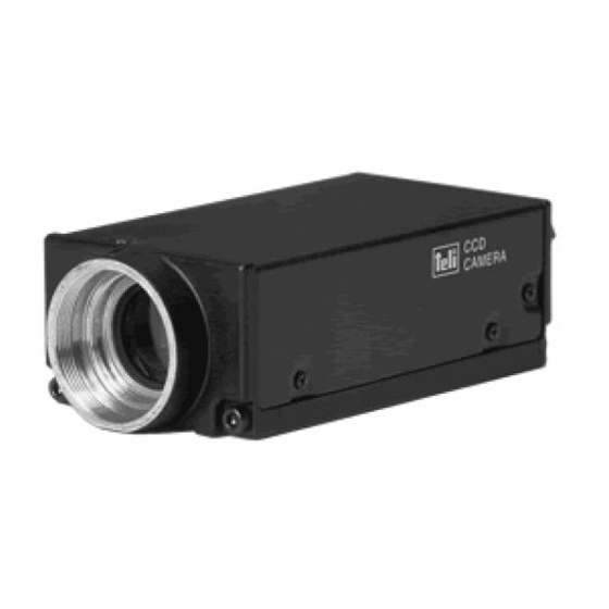
Summary of Contents for Toshiba CS3910BH
-
Page 1: Table Of Contents
’ 04/08/27 Ver1.01 High-Resolution CCD Camera CS3910BH 取 扱 説 明 書 Operation Manual Contents 1.PRODUCT DESCRIPTION 2.FEATURES 3.COMPONENTS 4.OPTION UNITS 5.REAR PANEL CONNECTORS 6.HOW TO MOUNT YOUR CAMERA 7.INTERFACE 8.FUNCTION 9.SPECIFICATIONS 10.TIMING CHART 11.EXTERNAL-VIEW DRAWINGS 作 成 承 認 確... -
Page 2: Product Description
CCD featuring high resolution. 2. FEATURES (1) High resolution CS3910BH features an high picture resolution through the adoption of a MEGA-pixel CCD (Total pixel number: 1,500,000 Active pixel number: 1,450,000 [1,392(H)×1,040(V)]). (2) Square-grid Pattern CCD Pixels in this CCD are aligned in a square grid pattern. This makes it easier to perform computation correctly for image processing use. -
Page 3: Components
’ 04/08/27 Ver1.01 3. COMPONENTS (1)Camera body ………………1 (2)Accessories Operation manual ………………1 4. OPTION DC IN Cable Model CPRC3700 Digital cable Digital video cable Tripod fixing metal 5. REAR PANEL CONNECTORS 1. DC IN/SYNC: DC+12V Power IN, Analog Video OUT, HD, VD, and TRIG IN, WEN out This connector is for connection with a power supply, image processing equipment 2. -
Page 4: How To Mount Your Camera
’ 04/08/27 Ver1.01 6. HOW TO MOUNT YOUR CAMERA (1) Option 1: Camera tripod fixing kit Use a dedicated tripod fixing kit (option unit) to fix your camera onto a tripod, etc. (See the diagrammatic sketch shown below) (2) Option 2 : Mounting holes (Bottom side) Put M3 screws through screw-holes to fix the camera. -
Page 5: Function
’ 04/08/27 Ver1.01 N.C. TRIG VD GND (2) DATA OUT Connector (Camera side): DX10A-36S Connector (Cable side): DX30A-36P, DX-36-CV1 (Cover) Pin. Signal name Pin. Signal name Pin. Signal name Pin. Signal name DATA0-H DATA4-L DATA9-H E.HD IN DATA0-L DATA5-H DATA9-L E.VD IN DATA1-H DATA5-L... - Page 6 ’ 04/08/27 Ver1.01 OFF ON OFF ON 1 ドラフトモード切替 AGC ON/OFF 切換 2 シャッタモード切換 3 シャッタスピード切換 4 使用しません(OFF固定) 使用しません(OFF固定) パーシャルスキャン ON/OFF 切換 使用しません(OFF固定) 使用しません(OFF固定) SW2 カメラ内部スイッチ SW1 カメラ背面スイッチ (1) Read out mode setting Change internal Dip SW1(Factory setting: OFF) OFF: 15Hz All Pixel Data Readout Mode (Normal mode) ON: 60Hz High-Speed draft mode (As vertical 2 lines in 8 lines read out at the same timing...
- Page 7 ’ 04/08/27 Ver1.01 (3)External sync setting(HD/VD) (a)SW1 Switch Function Function (indication) selection selection DATA OUT DATA External sync connector CONNECTOR selection DC IN/SYNC (DATA ⇔ DCIN) DCIN CONNECTOR (b)SW2 Switch Function Function (indication) selection selection External sync input/output Input selection Output (IN ⇔...
- Page 8 ’ 04/08/27 Ver1.01 -1 Fix mode Exposure-time (Setting with inner DIP SW) TRIG approx.5micro s (Exposure) VIDEO -2. Pulse mode 露光時間 (TRIGのパルス幅+約15μs) TRIG 20μs 約5μs CCD(露光) 映像出力 *The VD is output in sync with the next HD after light-exposure *本資料に記載された内容は予告なく変更する場合がありますので、予めご了承下さい。...
- Page 9 ’ 04/08/27 Ver1.01 (5) Multiple-shutter Mode Setting Exposure is done during the one frame period which comes immediately after TRIG IN. Images are output at the readout signal (E.VD) timing. If the exposure is made more than one time before the readout signal input, superposed images are output.
- Page 10 ’ 04/08/27 Ver1.01 (5) Partial-scan Mode Setting The partial-scan ON/OFF selection is made via the rear SW1 DIP5 (Initial factory setting: OFF) OFF: Normal mode ON: 1/2 --- Screen-center 1/2 readout 映像出力 (通常) 高速転送 通常転送 高速転送 映像出力 (中央1/2) * 中央1/2部分読み出し ◎ 総ライン 1046ライン...
-
Page 11: Specifications
’ 04/08/27 Ver1.01 9. SPECIFICATIONS Model CS3910BH [Electric specification] Image sensor Interline CCD Total pixel 1434(H) x 1050(V) Active pixel 1392(H) x 1040(V) Unit cell size 6.45(H) x 6.45(V) micrometer m Optical size Equivalent to 2/3 inch image pickup tube... - Page 12 ’ 04/08/27 Ver1.01 Pulse width: Longer than 5 micro s TTL level, Negative, Input impedance: 10k-ohm Repeating frequency 14.98Hz +/- 1 percent Pulse width: Over 1H(62.5 micro s) Trigger signal TTL level, Negative Input impedance: 10k-ohm Pulse width: Over 1H(62.5 micro s) Multiple-shutter readout signal TTL level, Negative Input impedance: 10k-ohm...
-
Page 13: Timing Chart
’ 04/08/27 Ver1.01 Table: Typical SRC X-axis: Wave-length Y-axis: Relative response 1000 Wavelength [nm] TIMING CHART 10-1. Digital output EIA RS644 standard (LVDS) Driver output voltage Plus/minus 350mV (Differential output) / 100-ohm H Rate DATA 17.5ns 276CLK 122CLK 1790CLK Total clock counts: 1790CLK / 1H DATA counts: 1392CLK / 1H... - Page 14 ’ 04/08/27 Ver1.01 V Rate DATA A=3H B=3H C=6H D=1040H E=1046H 10-2. External sync. E.VD 結合位相 E.HD 200ns以内 外部VDの立ち下がりに対して1H遅れて内部VDが立ち下がる。 結合位相は±200ns以内。 VD:1/15Hz≒65.4ms。1046H。パルス幅1H以上。 ジッタは20ns以内。 *本資料に記載された内容は予告なく変更する場合がありますので、予めご了承下さい。...
- Page 15 ’ 04/08/27 Ver1.01 10-3.Read out mode *15Hz All pixels read out 露光時間 1046H (内部DIP-SWにて設定) (15.29Hz) CCD(露光) DATA DATA 1 0 3 8 1 0 3 9 1 0 4 0 *60Hz High-speed draft read out 露光時間 262H (内部DIP-SWにて設定) (60.37Hz) CCD(露光) DATA 1 0 2 8 1 0 3 3...
-
Page 16: External-View Drawings
’ 04/08/27 Ver1.01 EXTERNAL-VIEW DRAWING *本資料に記載された内容は予告なく変更する場合がありますので、予めご了承下さい。...


Need help?
Do you have a question about the CS3910BH and is the answer not in the manual?
Questions and answers