
Related Manuals for Delta-T SPN1


Summary of Contents for Delta-T SPN1
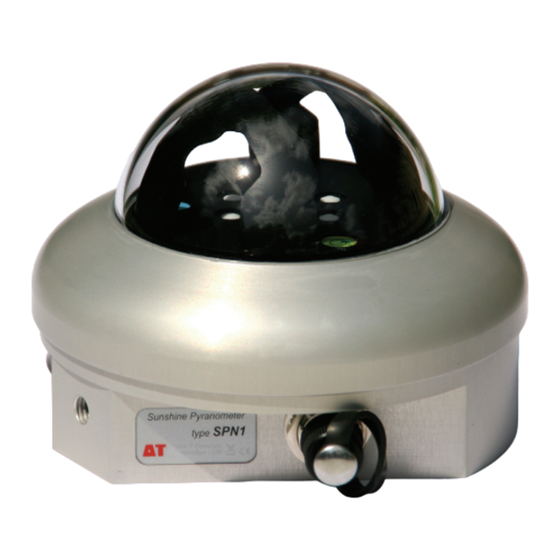
- Page 1 User Manual for the Sunshine Pyranometer SPN1 type SPN1-UM-1.0 Delta-T Devices Ltd...
- Page 2 Copyright All rights reserved. Under the copyright laws, this manual may not be copied, in whole or in part, without the written consent of Delta-T Devices Ltd. Under the law, copying includes translation into another language. Copyright © 2007 Delta-T Devices Limited SPN1 Sunshine Pyranometer optics design and theory are copyright ©...
-
Page 3: Table Of Contents
Terms and conditions of sale Service and spares Technical support Problems Troubleshooting Appendix A: Design and test summary Introduction Design objectives How the design evolved Calculation of outputs Test results Appendix B: RS232 commands Operating modes and serial commands Glossary SPN1 User Manual v1.0... -
Page 4: Introduction
The Delta-T Software and Manuals CD contains document files in Acrobat pdf format, and software. It includes this manual, the SPN1 Quick Start Guide, and other files relating to the SPN1. The CD also contains the SunRead software. Description and functions What it measures •... - Page 5 SunRead also provides a basic logging capability while the SPN1 is connected to the PC. Use with data logger • The three outputs of the SPN1 can be logged with a suitable data logger. The Total and Diffuse radiation millivolt outputs require two analogue channels. •...
-
Page 6: Construction
Differences from BF2 and BF3 • The BF2 and BF3 use the same optical design as the SPN1, and have a similar set of outputs. The BF2 & BF3 use photodiodes rather than thermopile sensors and measure PAR rather than energy. They are not as rugged or as accurate as the SPN1. -
Page 7: Accessories
Mounting The SPN1 may mounted either - directly onto a horizontal surface or via support arm type SPN1/ARM which includes an adapter for connecting to a vertical mast or on to the adjustable levelling baseplate (type SPN1/BP) M8 x 10 mm... -
Page 8: System Overview
System overview Introduction SPN1 User Manual v1.0... -
Page 9: Power Considerations
The 5-core serial cable type SPN1-RS232 is provided for connecting the SPN1 to a PC and is intended primarily for set-up and testing. It is 1.5 m long and terminated in a 5-pole M12 connector at the SPN1 and a DB9 connector at the PC end. - Page 10 Heater The SPN1 is fitted with an internal thermostatically controlled heater for protection against frost and condensation. The heater is mounted on the shadow mask, which will transfer heat around the inside of the dome and the top of the enclosure.
-
Page 11: Use With A Data Logger
Use with a data logger Analogue outputs The SPN1 is connected to a data logger via an 8-pole M12 waterproof connector using cable type SPN1/w-05. See also Cables on page 9. Additional weatherproof extension cables with M12 connectors at each end are also available (type EXT/M12-x where x = 5, 10 or 25m). - Page 12 The DL-Power and DL-Ground connections provide power to the sensor circuitry (but not the heater), and enable the analogue output signals. The Htr+ and Htr- cables provide power to the SPN1 heater. If this power supply is separate from the data logger power, it should be a fully isolated supply, so that no current flows between the power supply negative terminals.
- Page 13 No heater, SPN1 powered by logger warmup This connection would be appropriate for an isolated, battery powered logger such as the Delta-T GP1. The SPN1 heater is left disconnected. The logger must power up the SPN1 at least 100ms before the reading is taken.
- Page 14 Heater power available, SPN1 permanently enabled This connection would be appropriate to an installation with permanent mains power available. The SPN1 heater is powered up, and the SPN1 analogue outputs are permanently enabled for logging. Datalogger Total CH1+ Analogue input...
- Page 15 Suggested Sun output connections There are several possible ways of connecting up the SPN1 Sun output, depending on the capabilities of your data logger. The Sun output is open circuit when there is no sun, and connected to ground when there is sun.
- Page 16 DL-Gnd wire, and not the SigGND wire, otherwise you may see large offset voltages on your Total and Diffuse readings. LAMP DL-Power DL-Gnd Power supply 12 - 15V 1.5A Htr+ Htr- Outputs isolated from mains Introduction SPN1 User Manual v1.0...
-
Page 17: Ground Connections
In general the screen (black wire) should be connected to local earth near the logger. The SPN1 may also be connected to earth at its mounting point. If there is a lightning strike nearby, there may be large transient voltages induced between earth points, and in the sensor cabling. -
Page 18: Delta-T Data Logger Connections
The DL6 logger is not suitable for use with the SPN1. The input voltage range is insufficient and we provide no SPN1 sensor types or program for Warning: Do not attempt to attach an SPN1 to a DL6 via the 8 pole M12 connector on the DL6. It may damage the sensor. -
Page 19: Use With A Pc Or Serial Device
The SunRead software on the Delta-T Software and Manuals CD can be used to give an immediate display of the SPN1 outputs, and to give a very basic logging capability. The SPN1 sensor (not the internal heater) can take its power from the DTR signal of the PC serial port (about 4mA at 12V). -
Page 20: Accuracy And Errors
The construction of the SPN1 includes three separating elements between the atmosphere and the thermopiles, so this effect is minimal. The electronics within the SPN1 will only measure and output positive signals, so the output should never go below zero. -
Page 21: Technical Reference
Technical reference Specifications The SPN1 matches the WMO ‘Good Quality Pyranometer’ classification. The following accuracy figures give 95% confidence limits, i.e. 95% of individual readings will be within the stated limits under normal climatic conditions. Overall accuracy: Total ±5% Daily integrals (Global) and Diffuse radiation ±5% ±10 W.m... - Page 22 126 mm dia. x 94 mm high, 786g Part numbers and order codes Sunshine Pyranometer. Fitted with 5 and 8-pole M12 plugs. Supplied with 5m analogue signal and power cable type SPN1/w-05, SPN1 1.5 m serial cable type SPN1-RS232, SPN1 Quick Start Guide, calibration certificate and Delta-T Software and Manuals CD.
-
Page 23: Spn1 Spectral Response
Solar SPN1 0.15 0.05 1000 1500 2000 2500 3000 W avelength nm This shows the spectral response of the Sunshine Pyranometer (thermopile, diffusers and dome combined), shown with the solar spectrum at ground level SPN1 User Manual v1.0 Technical reference... -
Page 24: Spn1 Cosine Response
Ideal cosine Absolute output Relative error 2% limits Zenith angle (degrees) This graph shows the typical cosine response of the Sunshine Pyranometer compared to the ideal cosine curve. The upper curve shows the relative accuracy Technical reference SPN1 User Manual v1.0... -
Page 25: Routine Maintenance
Renew if 50% or upper indicator pink The humidity of the air inside the actual SPN1 dome is indicated by a coloured panel under the dome. The dessicant indicator plug has two more indicators. Blue indicates dry, pink indicates a humidity threshold has been exceeded. - Page 26 Use the sealing caps supplied to protect any connectors you are not using from water and dust. The SPN1 is robust, but does not have a drop test rating. The glass dome will break if you hit it. Do not drop it.
-
Page 27: Calibration Procedure And Traceability
Calibration procedure and traceability Factory calibration procedure The SPN1 is calibrated at the factory against a transfer standard SPN1. Calibration is done before the shadow mask is fitted, so that all the thermopile sensors can be uniformly exposed. Units are calibrated in a 12 inch integrating sphere with a light source which approximately matches bright sunlight in intensity and spectral composition. - Page 28 Technical reference SPN1 User Manual v1.0...
-
Page 29: Warranty And Service
Delta-T shall not be liable to the buyer by reason of any delay or failure to perform our obligations in relation to the goods and/or services, if the delay or failure was due to any cause beyond the Delta-T’s reasonable... -
Page 30: Service And Spares
No goods or equipment should be returned to Delta-T without first obtaining the agreement of Delta-T or our distributor. On receipt at Delta-T, the goods will be inspected and the user informed of the likely cost and delay. We normally expect to complete repairs within a few working days of receiving the equipment. -
Page 31: Problems
Software version numbers and hardware serial numbers (see below) Locating version and serial numbers The SPN1 serial number label is on the lower part of the case. The internal software (firmware) version number is displayed in the About box using SunRead. -
Page 32: Appendix A: Design And Test Summary
Appendix A: Design and test summary This appendix gives a brief description of how the SPN1 design works and a summary of the results of the test program. More detailed versions of these are available from Delta-T. Introduction Measurement of Direct and Diffuse components of solar radiation has many applications - in modelling the interaction of light with crop canopies, studying the energy balance of structures, or as a meteorological indicator. -
Page 33: Calculation Of Outputs
Let MAX and MIN be the largest and smallest thermopile reading of the seven thermopiles, after being adjusted for any calibration factors (calibration is done in the solar lamp integrating sphere against a transfer standard SPN1) Then TOTAL = MAX + MIN DIFFUSE = 2 x MIN x 1.02 (the extra 2% takes away a small... -
Page 34: Test Results
SPN1 Diff 27 April 2006 This graph shows a typical daily output from the SPN1. It is plotted against two Kipp CM6 pyranometers, one shaded by a disk on a solar tracking arm. This day started overcast, with cloud breaking up during the middle of the day, followed by a cloudless evening. - Page 35 1000 CM6B Global & Diffuse W .m -2 This graph shows SPN1 Total (lower trace) and Diffuse (upper trace) outputs compared with two Kipp CM6s and a solar tracking shade disk. Data recorded at Winster, Derbyshire between September and December 2004. The graph plots hourly averages of readings every 5 seconds.
- Page 36 120 W.m-2 in the Direct beam. Data recorded at Napier University, Edinburgh between February and July 2001. Comparable data from an adjacent Campbell-Stokes recorder is also plotted. The SPN1 uses a very similar algorithm, and will give comparable results.
-
Page 37: Appendix B: Rs232 Commands
Operating modes and serial commands The SPN1 can be interrogated from any serial port terminal program such as Windows HyperTerminal. Set the RS232 settings to 9600 baud, No parity, 8 Data bits, 1 stop bit., Flow control: none. -
Page 38: Test Mode
SPN1 v1.03 Mar 13 Status information – code version 2007<CR> Output units - W.m Units: W.m <CR> Battery voltage, radio link status. (Neither normally installed in SPN1) 1mV radio off <CR> Instrument serial number A106<CR> <CR> TEST: Enter TEST mode. - Page 39 Batt 0 mV Ext 5874 Reports battery voltage (not usually fitted mV Vcc 3299 mV on SPN1), external supply, and regulated 2006/01/10 00:02:43 Vcc. Also reports if DL-POWER or HTR- POWER inputs are active. Reports date & time (reset on power up)
- Page 40 Onnnn,nnnn set DACs Pn.nx read/set pin x is 01= Q Scan PDs R Reset to normal S Send data Tn.nn Sunshine ratio WRITE user cal to default XncccCR Write ccc to string Xn Appendix B: RS232 commands SPN1 User Manual v1.0...
-
Page 41: Glossary
Azimuth angle - the horizontal angle between the sun, or a light source simulating the sun, and North, increasing in the direction NESW. The SPN1 does not have to be aligned towards North for correct operation (unlike most other devices). - Page 42 Heater Cosine response 24, 41 Latitude capability data logger analogue outputs Desiccant Design and Test Summary maintenance Diffuse light Mounting Direct Direct beam DL2e Logger DL6 Logger Non-linearity Index SPN1 User Manual v1.0...
- Page 43 Size & Weight solar spectrum Spares Warranty Specifications Wiring Spectral response 21, 23 analogue signals and heater power Spectral sensitivity variation output schematic SPN1 SPN1 output SPN1/BP levelling base plate Zenith angle levelling plate Zero offsets SPN1 User Manual v1.0 Index...
Need help?
Do you have a question about the SPN1 and is the answer not in the manual?
Questions and answers