
Related Manuals for REO REOVIB series


Summary of Contents for REO REOVIB series
- Page 1 REOVIB Control units for flexible automation Hand book for installing and setting up REOVIB controllers Concepts, questions and background information...
-
Page 2: Table Of Contents
Contents 1.0 General information about the REOVIB product range ................ 1 2.0 Background to feed engineering ......................2 2.1 The vibration wave form ........................2 2.2 The feed waveform ..........................3 2.3 Vibrating frequency and resonance ....................3 2.3.1 Resonant condition ........................4 2.3.2 Under critical operation ........................ -
Page 3: General Information About The Reovib Product Range
1.0 General information about the REOVIB product range The REOVIB range from REO ELEKTRONIK AG comprises all equipment produced for vibratory feeder engineering. This includes controllers for vibratory feeders, measuring and monitoring equipment, with corre- sponding transducers. All types of feeder control units are available, using thyristors or triacs with phase-angle control or the newer technique employing a frequency inverter. -
Page 4: Background To Feed Engineering
2.0 Background to feed engineering The use of mechanical vibrators for feeding material, dosing, screening or mixing of goods is long estab- lished. Drives, with so called out-of-balance motors and vibrating equipment with electromagnetic drives are certainly the most widely applied. Electromagnetic drives are more frequently used in automation engineer- ing and hence some fundamental differences require further explanation. -
Page 5: The Feed Waveform
2.2 The feed wave form Diagram 2 shows a vibratory drive unit with a unidirectional deflection (linear feeder). The direction of move- ment is determined by the vibrating angle. The material on the track is accelerated along the deflection path. rajectory Vibrating angle α... -
Page 6: Resonant Condition
2.3.1 Resonant condition Diagram 4 shows various resonance curves for a feeder with different damping levels. This demonstrates the relationship between damping and the shift in resonant frequency. < f > f without damping (theoretical). b – d increasing damping levels. drive frequency. -
Page 7: Regulated Drive Control
3.2 Regulated drive control It is possible to operate a vibratory feeder at resonance if a frequency inverter is used for holding the feeder at resonant frequency and the amplitude at a level determined by a selected set-point. To achieve this, the vibratory movement has to be measured and fed back to the frequency controller. -
Page 8: Reovib - Terms
5.0 REOVIB – Terms Through the course of time, various terms that sometimes seems different but is really the same, relating to equipment, functions and characteristics, have evolved. These have been compiled, below, together with explanations. In instances where there are several terms relating to a theme, the most widely used expres- sion is underlined. - Page 9 Half-wave control Only one half of the mains sine wave is controlled. The vibrating frequency 3000 vibs / min is the same as the mains frequency. 50 Hz operation 3000 vibrations/ min at 50 Hz mains frequency 3600 vibrations/ min at 60 Hz mains frequency Soft start To prevent a sudden switch-on to full feeder throughput;...
-
Page 10: Functions Of Controls Units
6.0 Functions of control units 6.1 Enable input or Stop/Start input An input for interlocking with a supervisory systemm e.g. PLC or several controllers together, with a specific relationship, e.g. paddle-switch regulation of a pre-feeder from a bowl feeder (see status output). Inputs are usually configured for use with contacts or a 24 VDC signal. -
Page 11: Track Control
6.8 Track control Material flow can be regulated by employing track control, whereby unnecessary feeder running time (de- creasing noise and energy consumption) and degradation of the component can be reduced. 6.8.1 Single point control A bowl feeder is controlled from a material sensor located along the component track. The feeder is switched on and off in response to a sensor, which monitors the material level. -
Page 12: Min/Max Control
6.8.2 Min/Max Control When two sensors are used for track control, the feeder is switched off when material builds up beyond the “max“ sensor and the time delay has elapsed (t5). The feeder switches on again when the product level drops below the “min“... -
Page 13: Controls
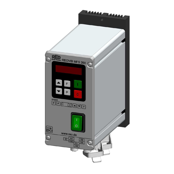
7.0 Controls 7.1 Analogue Units Potentiometers and link switches are used for adjusting throughput configuring analogue units to operate with specific feeders. The functions and locations of the potentiometers and link switches are fully explained in the operating instruction manual for the controller. 7.2 Digital units Digital units are provided with a display and programming keys that are used for adjusting all parameters and the feeder throughput. -
Page 14: Reset Set Point To Zero
1. Press the “P“ key 2. Select the code number with the cursor keys 3. Press the “P“ key. This displays the first menu point. The required menu point can be found by repeat- edly pressing the “P“ key (scrolling). 4. -
Page 15: General Manufactures Instructions For The Installation Of Reovib Control Units
All setting routines are commenced by pressing the programming button “P“. The following diagram should clarify the sequence in which keys are pressed: Example: To set feeder parameters Feeder Speed 0...100 % Maximum limit 100...5 % Frequency [Hz] Soft start time 0...5 sec. Soft stop time 0...5 sec. -
Page 16: Before Installation
8.1 Before installation Read the instruction manual carefully, in certain circumstances there are additional instructions relevant • to the installation of a particular controller (special attention should be given to warnings). Isolate from the mains supply, i.e. do not plug into mains socket. •... -
Page 17: Setting The Feeder Throughput
For 100Hz (120Hz) vibrating frequency, this switch must be closed or a link fitted and for 50Hz (60Hz) vi- brating frequency the switch must be open, or a link is removed. In the case of frequency inverters the vibrating frequency has a step less setting through the operator front panel. -
Page 18: Setup Menu For Regulation Control
9.0.1 Set up menu for regulation control E.g. REOVIB MFS 068 Code 008 Vib. frequency [Hz] Select regulation mode ACC. = 0 = Control without sensor ACC. = I = Regulation with sensor Regulation P characteristic (Circuit gain Regulation I characteristic damps oscillations of the feeder Automatic frequency control A.F.C. -
Page 19: Setting Up Instruction For Using A Controller In Regulation Mode
Using an accelerometer with an output signal of 0.3 V/g the sensor generates a peak voltage of 4.5V for a peak acceleration of 15g (example 1), corresponding to a 3.18Vrms value. Example 1: => 15g => 4.5 V => 3.18 Vrms Example 2: =>... -
Page 20: Diagnostic Displays For Non-Optimized Regulation Settings
9.5 Diagnostic displays for non-optimized regulation settings Controller has reached maximum output power. The feedback signal from the sensor (accelerometer) is too weak relative to the selected throughput setting. Reduce Parameter “P“ in menu C 096 or C 008. The feedback signal from the sensor (accelerometer) is too strong. Alternating display: The regulator oscillates rapidly. -
Page 21: Trouble Shooting - Analogue Controllers
In regulation mode the magnitude of the output signal has a direct affect on the maximum amplitude of the feeder. On bowl feeders it is advisable to fit the sensor as near as possible to the outside diameter and in this position it will be subjected to the greatest movement. -
Page 22: Trouble Shooting - Frequency Controllers
14.0 Trouble shooting - Frequency controllers Problem Possible reason Remedy Feeder does not vibrate amplitude is set to zero increase amplitude by pressing • • [P] key twice in menu C 000 and using arrow keys • carry out resonant frequency •... - Page 23 Error message Type of fault Possible reason Remedy ERROR – OL Output power too coil power is too high use a controller with a higher • • high current rating frequency is set too low increase frequency • • coil air-gap is too large reduce air-gap •...
- Page 24 REO Shanghai Inductive Components Co., Ltd No. 536 ShangFeng Road · Pudong, 201201 Shanghai · China REO Vibratory Feeding and Power Electronics Division Tel.: +86 (0)21 5858 0686 · Fax: +86 (0)21 5858 0289 Brühler Straße 100 · D-42657 Solingen E-Mail: info@reo.cn ·...
Need help?
Do you have a question about the REOVIB series and is the answer not in the manual?
Questions and answers