Advertisement
Quick Links
Advertisement

Subscribe to Our Youtube Channel
Related Manuals for ReadyMadeRC Anaconda


Summary of Contents for ReadyMadeRC Anaconda
- Page 1 Ready Made RC, LLC Assembly Instructions for: Updated 9/22/14 RMRC Anaconda...
-
Page 2: Table Of Contents
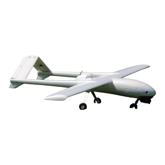
Thank you for purchasing the RMRC Anaconda! It is important to read the manual in its entirety before your maiden flight. This model is not intended for new or beginner pilots. It requires a large, smooth takeoff/landing area and does not have self-correcting tendencies that most new pilots require. -
Page 3: Parts List For Kit
Kit Package Contents: Foam parts (A) 1. Main Wing Set 2. Ruddervators 3. Front Boom Covers (Under Main Wings) 4. Rear Boom Covers (2 halves each) 5. Mid Boom Covers 6. Motor Nacelle 7. Canopy 8. Removable Camera Pod 9. Fuselage Halves... - Page 4 Carbon Fiber (B) 1. 480mm x 8mm (2 pieces) 2. 1000mm x 12mm 3. 870mm x 6mm 4. 740mm x 13.5 mm (2 pieces) Notice stopper screws 5. 870mm x 16mm (2 Pieces)
- Page 5 Plastic parts (C) 1. Front Boom Anchors (Notice that 2 have retainer for female stereo jack) 2. Rear Boom Anchors 3. Control Horns (May be push through style) 4. Bolt Bushings for Main Wing 5. Nut Anchors for Ruddervator Joiner 6.
- Page 6 Wood Parts (D) 1. Adjustable Battery Tray 2. Motor Mount (Choose according to motor size) 44mm vs 50mm X pattern 3. Wing/Fuselage Anchors 4. Rear Landing Gear Anchors (2 pieces, one is not pictured) 5. Camera Bay Hooks 6. Camera Bay Anchor 7.
- Page 7 Hardware (E) 1. Rear Landing Gear 2. Rear Wheels 3. Front Wheel 4. Canopy Magnets 5. Nose Landing Gear 6. Linkage Stoppers 7. T-Nuts, Bolts, Nylon Lock Nuts 8. Wing Bolts with Washers 9. Ruddervator Joiner 10. Control Rods 11. Servo Leads 12.
-
Page 8: Parts List For Pnp
PNP Parts Included: Fuselage Right and Left Wings Right and Left Ruddervators Tail Booms Decal Sheets (2) Wing Spars Front and Rear Tail Boom Covers Right and Left Motor Nacelle Rear Landing Gear ... -
Page 9: Fuselage Assembly
Fuselage Assembly 1. Locate wood motor mount plates (2D) and place the X bracket from your motor onto it. Once you have chosen the correct size for your motor, you may set the other aside. 2. Insert T-Nuts into wood pieces and secure with epoxy. Leave one of the rear landing gear plates with no T-Nuts installed. - Page 10 Note that wing bolts are used to help align wooden anchors during gluing process: 5. Carefully press opposite half of fuselage together and secure with tape. a. Make sure wing anchors and motor mount are still securely in place...
- Page 11 6. Locate Nose Gear and Steering Servo Anchor (6C) and use epoxy to secure in nose of fuselage. Try to avoid excess epoxy from blocking servo path. 7. Locate rear landing gear anchors (4D). One should have T-Nuts glued in place and one should not.
- Page 12 8. Locate Nose Gear (5E) and white control horn. a. Install linkage stopper as shown b. Tighten control horn with 1.5mm tool onto flat spot of nose gear. c. Push nose gear through forward hole in plastic anchor d. Use collet and 1.5mm tool to secure. 9.
- Page 13 10. Locate and Install wheels on front and rear landing gear. (2E & 3E) a. Use appropriate collet and 1.5 tool to secure 11. Locate Canopy (7A) and Magnets (4E) a. Trim excess foam flashing from canopy with hobby knife b.
- Page 14 12. Locate wood camera bay anchor (6D) a. Epoxy T-Nuts into place as shown. i. M3 for gimbal mount ii. M4 for center b. Glue plate under fuselage as shown. i. Be careful not to have excess glue where wood hooks will travel.
- Page 15 13. Locate Camera Bay (8A) and Wood Bay Hooks (5D) a. Glue hooks into allotted space in the camera pod. This will allow the pod to lock into the bay anchor in the fuselage. b. Repeat steps used to glue magnets in canopy for camera bay. 14.
- Page 16 15. Locate Battery Tray (1D) and Battery Strap (12E) a. Loop Battery strap into rear or center slots in battery tray. b. Slide battery tray into grooves in forward fuselage. c. Secure with M4 Bolt and washer. This is adjustable for center of gravity. 16.
-
Page 17: Wing Assembly
Wing Assembly 1. Locate Forward Boom Anchors (1C) and Wing Spars (1B & 4B) a. Remove spar covers in wing and dry fit boom anchors. i. Note that female servo jacks must be towards leading edge of wing and tail booms must pass through. ii. - Page 18 3. Locate 4x M3x15 bolts and 4x locking nuts and insert them as shown. a. Do not compress the clap at this time. b. Apply glue to nuts to prevent them from backing out when pod cover is installed. 4. Locate and center aileron servos. a.
- Page 19 5. Locate control horns (3C) a. Insert into wing and fasten on top side. b. Install linkage stopper to control horn. c. Insert control rod into horn and tighten linkage stopper. i. Make sure that aileron is flush with wing. d.
- Page 20 Update 9/22/14 – We now recommend installing the boom covers after final assembly. This allows you to make sure the stereo jacks have fully seated. You should not need to see this again after the first time and you are free to glue or use supplied tape as you wish. a.
- Page 21 d. Install linage stoppers into control horns. e. Glue flap servos into position and setup linkage as shown. i. To achieve full travel, the servo must be off-center at zero position. Flaps at zero position:...
-
Page 22: Tail Assembly
Flaps at full position: f. Route servo wires neatly into channel and glue into place. Tail Assembly 1. Locate pieces 2A, 4A, 2C, 5C, 9E as shown below:... - Page 23 a. Dry fit foam stabilizers onto boom anchors and place onto corresponding ruddervator to ensure proper fitment. b. Trimming of the boom anchor clamps may be required for proper operation. c. Insert M3 bolts into housing and secure with lock nut. i.
- Page 24 d. Glue boom anchors onto ruddervators as shown below: 2. Locate and center ruddervator servos. a. Install servo horn and glue servo into position. i. Some trimming of the foam may be required depending on servo used. b. Install control rod stopper onto control horn. c.
- Page 25 3. Glue inner boom anchor cover (4A) onto anchor and ruddervator as shown. a. Note: glue servo wire along channel (green line) b. Glue outer boom cover onto anchor and ruddervator as shown. i. Note: avoid applying glue to bolts. ii.
- Page 26 4. Locate bracket 9E, 4x M3 bolt/nuts from E7, and square anchors from C5. a. Glue anchors into ruddervators as shown. b. Attach bracket to one ruddervator and tighten bolts. c. Attach opposite ruddervator and tighten bolts. 5. Tail booms – Locate foam boom covers (A5) and CF booms (B5) a.
- Page 27 c. Tape together and allow time for glue to cure. d. Insert CF booms into covers with the female servo side towards the narrow portion of the cover as shown below.
-
Page 28: Final Assembly For Kit And Pnp
Final Assembly Update 9/22/14: If you are assembling the PNP version, we recommend that you remove your motor screws and apply a small amount of blue thread locker. 1. Locate assembled main wings and CF spars 2B & 3B a. Insert CF spar 2B into forward spar on one wing until it stops. b. - Page 29 a. Once fully inserted, tighten down clamps with 2.5mm tool. 3. Slide ruddervators onto rear portion of tail booms a. Tighten clamps once fully inserted and no gaps in foam are showing. i. This may be more difficult during the first installation. b.
- Page 30 c. You should now have fully assembled the wing and tail portions. 4. Plug in “Y” servo cables from E11 for ailerons and flaps if you have chosen to install them. a. Locate bolts and washers from E8. 5. Place wing and tail on top of assembled fuselage. i.
-
Page 31: Setup Tips
6. You should now have an assembled aircraft. Aircraft Setup 1. After you have installed your RC receiver, you will need special V-Tail mixing in your transmitter’s menu system. Please see your user manual for more information if you are having trouble. If you do not have V-Tail mixing, or just want to save the extra channel, you may simply setup the tail with a Y-harness and eliminate the rudder. - Page 32 For our personal preference, we use 100% travel on all of our end points for the Anaconda. We suggest that if your RC transmitter has the capability, to use a 2 or 3 position switch to set throws at 60% and 80%. This will allow you to change mid-flight if you find that you have too much or too little control over the aircraft.
Need help?
Do you have a question about the Anaconda and is the answer not in the manual?
Questions and answers