
Related Manuals for Okofen PELLETRONIC TOUCH

Summary of Contents for Okofen PELLETRONIC TOUCH
- Page 1 Operating Manual PELLETRONIC TOUCH TOUCH V2.00 NGLISH E1389EN 2.0 Europe’s specialist in pellet heating...
- Page 2 Title: Operating manual Pelletronic Touch Article number: E1389EN 2.0 Version: Version valid from: 05/2013 Approved: Humberger Stephan Author: ÖkoFEN Forschungs- und EntwicklungsgesmbH Technical editorial department Gewerbepark 1 A-4133 Niederkappel AUSTRIA Tel.: 0043(0)7286/7450 Fax: 0043(0)7286/7450/10 oekofen@pelletsheizung.at www.oekofen.com © by ÖkoFEN Forschungs- und EntwicklungsgesmbH...
-
Page 3: Table Of Contents
17.4 Assembly or disassembly of the power supply ....................49 17.5 Assembly and disassembly of the heating controller board ................50 18 Description of the Operating device module ....................51 18.1 Replacing a Touch operating device ......................51 19 Software ............................... 52 Operating manual Pelletronic Touch E1389EN 2.0... - Page 4 30 Appendix ..............................87 30.1 Calibration..............................87 30.2 Connection plan............................89 30.3 Wiring diagrams............................93 30.4 Cable specification Pelletronic Touch ......................95 30.5 Hydraulic connecting diagrams ........................96 30.6 Default values and settings......................... 103 Operating manual Pelletronic Touch E1389EN 2.0...
-
Page 5: Dear Customer
In this way, we secure our technological advantage. We have already received many national and international awards for our products. All our products comply with European standards in respect of quality, efficiency and emissions. Operating manual Pelletronic Touch E1389EN 2.0... -
Page 6: Use Only For The Purpose Intended
The following harmonised standards have been applied: Standards Designation EN 303–5 Boilers Part 5 EN 14961–2 Pellets for non-industrial use The following Austrian standards, guidelines and specifications have been applied: Standards Designation TRVB H 118 Technical directive on fire prevention Operating manual Pelletronic Touch E1389EN 2.0... -
Page 7: Types Of Safety Warning Sign
Note - indicates a situation that could lead to property damage. 2. Consequences of risk Effects and consequences resulting from incorrect operation. 3. Avoiding risk Observing safety instructions ensures that the heating system is operated safely Operating manual Pelletronic Touch E1389EN 2.0... -
Page 8: Pelletronic Heating Controller And Operating Device With Touch Screen
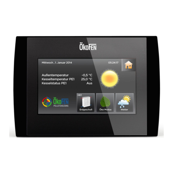
The touch panel is dark when in standby mode. As soon as the surface of the screen is touched, it lights up and displays the opening window. Boiler temperature Outside temperature Hour The icon house takes to the main menu. Chimney sweep Favorite 2 Favorite 1 Operating manual Pelletronic Touch E1389EN 2.0... -
Page 9: Chimney Sweep
If yes then press the tick box. • Boiler temperature set is 60°C for the total running time of 30 minutes. • It displays the actual boiler temperature and delay time. • Chimney sweep is stopped with Cancel. Operating manual Pelletronic Touch E1389EN 2.0... -
Page 10: User Controls And Their Function
Cancel – You return to the menu item. Input of a new value was not accepted. The original value is then restored. Help function – inactive g. Confirm h. Numeric keyboard – used to enter values within the Min - Max range. Operating manual Pelletronic Touch E1389EN 2.0... - Page 11 Choose a status text. The setup menu closes automatically and the chosen status text is displayed in the menu. Note Although a scroll down menu is open, the navigation/parameter icons behind are still active and can be used. Operating manual Pelletronic Touch E1389EN 2.0...
-
Page 12: Main Menu
Pelletronic heating controller and operating device with touch screen. 4.5 Main Menu In the main menu all submenus are displayed. Press the icon required to access that programme. Menu navigation of Pelletronic Touch Operating manual Pelletronic Touch E1389EN 2.0... -
Page 13: Mode
The adjusted operating mode of the DHW is active. The adjusted operating mode of the heating circuits is active. The frost protection function is active. The operating mode heating circuits, domestic hot water and solar are described in the respective chapters. Operating manual Pelletronic Touch E1389EN 2.0... -
Page 14: Measuring Values
In the menu item System you see all actual and set values of the overall heating system. In the menu item Allocation you see which heating circuits are allocated to the boiler or to the accumulatores. Operating manual Pelletronic Touch E1389EN 2.0... - Page 15 Measuring Values System Status is an overview of the whole heating system. Operating manual Pelletronic Touch E1389EN 2.0...
-
Page 16: Heating Circuit
Choose your room temperature (Temperature within the heating times). Room Temp Set back Choose Room Temp Set back (= Minimum temperature beyond the heating times). Time Allocation Activate Time 1 (= Time programme 1) and Time 2. Operating manual Pelletronic Touch E1389EN 2.0... -
Page 17: Measuring Values Heating Circuit
The activated days are displayed in green. Enter the heating times With for these heating days you switch between (Mo-Th). the heating blocks. You can activate or deactivate heating days in the heating block. Operating manual Pelletronic Touch E1389EN 2.0... - Page 18 Go back with and heating times Select Time 2. assigned. For each circuit are two time programmes. You can select two-time programs. In the menu item Time Allocation you can activate Time programme 1 or 2. Operating manual Pelletronic Touch E1389EN 2.0...
-
Page 19: Party
Enter the departure (start time) and return (finish date) and activate the vacation programme. Note To return to an already temperate building you should enter the day before your return as the finish date. Operating manual Pelletronic Touch E1389EN 2.0... -
Page 20: Heating Curve And Heating Limits
H limit set temperature If the average outside temperature is higher than the set temperature, the heating circuit switches off in the Set back mode. Operating manual Pelletronic Touch E1389EN 2.0... - Page 21 Decrease heating curving value by 0.2 Increase heating curving value by 0.2 Decrease base point value by 5° Increase base point value by 5° -20 to +5°C Decrease heating curve value by 0.2 Increase heating curve value by 0.2 Operating manual Pelletronic Touch E1389EN 2.0...
- Page 22 The room temperature hysteresis prevents the cycling (On Off On Off...) of the heating circuit pump: If the Set room temperature + room temperature hysteresis is reached, the associated pump stops. If the Set room temperature is – 1°C, the pump switches on again. Operating manual Pelletronic Touch E1389EN 2.0...
- Page 23 Heating Circuit Operating manual Pelletronic Touch E1389EN 2.0...
-
Page 24: Screed Programme
Flow temperature set appears for every heating day. Select every single day and adjust the Flow temperature set. The pre-set Flow temperature set per day is 20 °C. With you get to all other days. Operating manual Pelletronic Touch E1389EN 2.0... -
Page 25: Domestic Hot Water (Dhw)
In the DHW time programme you set the times of the hot-water processing. The DHW time programme works the same way as the heating circuit programme. See chapter Time programme Heating circuit, page 17 Operating manual Pelletronic Touch E1389EN 2.0... -
Page 26: Measuring Values Domestic Hot Water
Time 1 (=Time programme 1) and Time 2 are in the menu Domestic hot water. The domestic hot water time programme works the same way as the heating circuit time programme. See chapter 7.2 Time programme Heating circuit, page 17 Operating manual Pelletronic Touch E1389EN 2.0... -
Page 27: Dhw Return Pump
Measuring values DHW Return pump is in menu DHW Return pump. You see all the Heating circuit corresponding measuring values: • Actual value • Set value • Inputs (sensores) • Outputs (pumps, mixer und motors) Operating manual Pelletronic Touch E1389EN 2.0... -
Page 28: Time Programme Dhw Return Pump
Time 1 (=Time programme 1) and Time 2 are in the menu DHW return pump. The DHW return pump time programme works the same way as the heating circuit time programme. See chapter 7.2 Time programme Heating circuit, page 17 Operating manual Pelletronic Touch E1389EN 2.0... -
Page 29: Solar
10.1 Measuring values Solar Measuring values Solar is in the menu Solar. It displays all measuring values of Solar: • Actual values • Set values • Inputs (sensors) • Outputs (pumps, mixer and motors) Operating manual Pelletronic Touch E1389EN 2.0... -
Page 30: Solar Circuit
At this temperature the solar pump starts to run at minimum speed. Collector smoothing Min Temp Collector smoothing The pump speed increases within the set range as the collector temperature Control range increases. Operating manual Pelletronic Touch E1389EN 2.0... -
Page 31: Yield - Solar Energy
Display of the solar energy since the last set date. • Flow rate Display of the current flow rate, refreshes every 60 sec. • Flow temperature Display of the current flow temperature • Return temperature Display of the current return temperature Operating manual Pelletronic Touch E1389EN 2.0... -
Page 32: Pellematic
2 minutes. After that the burner motor runs in permanent operation and transports pellets to the burner plate. In heating systems with auger delivery it will also operate the extraction auger in permanent operation. Operating manual Pelletronic Touch E1389EN 2.0... -
Page 33: Measuring Values Pellematic
Average Run Time Average Run Time according to the number of ignitions Number Ignition Number of Ignitions with electrical ignition Ignition Stick Status (On Off) Ignition Stick Motor B Cleaning Status (On Off) Motor B Cleaning Operating manual Pelletronic Touch E1389EN 2.0... -
Page 34: Full Power
De-ashing system is in the menu Pellematic. plate cleaning work parallel. • Min run time of the boiler until next de-ashing procedure. Value adjustable • Ash delivery time Is the run time of the ash auger. Value adjustable. Operating manual Pelletronic Touch E1389EN 2.0... -
Page 35: Fresh Water Module
Default value -1h: It is not performed a second cleaning sequence. Min Run Time Min Run Time of the boiler until next cleaning sequence. Value adjustable. Cleaning Time Duration of the boiler cleaning sequence in seconds. Value adjustable. Operating manual Pelletronic Touch E1389EN 2.0... -
Page 36: Suction System
= 0 then no pulse mode. Suction Interval Run time of burner auger until next Suction Interval. The hopper is filled at this time regardless of whether it is empty or not. Operating manual Pelletronic Touch E1389EN 2.0... -
Page 37: Level Detection System
Correction Value Only if mode Flexi Tank or Storage room is chosen. Set the display of the current weight to 0 by putting in the negative of the current weight shown Operating manual Pelletronic Touch E1389EN 2.0... -
Page 38: Heat Main Pump
Switch the Heat Main Pump On or Off. Note For each heating controller only one Heat Main Pump or circulation pump can be used. The Heat Main Pump and the circulation pump are closed from each other. Operating manual Pelletronic Touch E1389EN 2.0... -
Page 39: General
Select the menu item you wish to be displayed as Favorite 1 in the Start menu. The selected item is now green, this icon is now displayed in the start menu and active. Operating manual Pelletronic Touch E1389EN 2.0... -
Page 40: Local Settings
Choose between the languages German, English UK, English U.S. French, Spanish, Italian, Dutch, Danish and Russian. Unit You can choose between metric and imperial measuring systems. Date Set the current date. Time Set the current time. Operating manual Pelletronic Touch E1389EN 2.0... -
Page 41: Malfunction
The fault texts have 3 status • C..CURRENT — when the fault occurs • Q..QUIT — when the fault has been rectified • G..GONE — when the fault has been reset by pressing ENTER Operating manual Pelletronic Touch E1389EN 2.0... -
Page 42: Software
Software Software Software shows the current version of software in use. Software is in the Main menu. Operating manual Pelletronic Touch E1389EN 2.0... -
Page 43: Code Input
Code Input Code Input The heating controller is composed of 2 levels, one for customer and one for OkoFEN service technicians. At the customer level the operator can adjust the heating system to their needs. At the OkoFEN service technician level advanced settings for startup and customisation of the heating systems are possible. -
Page 44: Start Up
To perform the installation-specific settings, you must enter via code input into the service technician level. See Chapter 15 Code Input, page 43 Menu guide shows the menu levels and menu items of the Pelletronic heating controller with the additional menu items for ÖkoFEN Service technicians Operating manual Pelletronic Touch E1389EN 2.0... -
Page 45: Description Of The Heating Controller Module
Slot for an optional power supply Extra low voltage (PELV) (The power supply is needed when the burner control CMP 06.2 is used. The power supply takes over the bus supply.) Fuse 6,3 A (fast) for X31 and X33 Operating manual Pelletronic Touch E1389EN 2.0... -
Page 46: Setting The Address At The Heating Controller
Adjust the order by using the address switch, this is only possible if the heating system is powered down. Note The settings in the remote control are described in the Operation instruction Remote controller. Operating manual Pelletronic Touch E1389EN 2.0... -
Page 47: Setting The Address At The Burner Controller
At the operating with cascade systems you assign to every boiler with 0 beginning the suitable number. Property damage Adjust the order using the address switch this is only possible when the system is powered down. Operating manual Pelletronic Touch E1389EN 2.0... -
Page 48: Setting The Address At The Boiler Controller Cmp
Learn Periphery. The different Pellematic plugs 1 to 4 must be numbered according to the boiler numbers. Property damage Adjust the order using the address switch this is only possible when the system is powered down. Operating manual Pelletronic Touch E1389EN 2.0... -
Page 49: Assembly Or Disassembly Of The Power Supply
Description of the heating controller module 17.4 Assembly or disassembly of the power supply Operating manual Pelletronic Touch E1389EN 2.0... -
Page 50: Assembly And Disassembly Of The Heating Controller Board
See previous chapter 17.4 Assembly or disassembly of the power supply, page 49 5. Disassemble the circuit board from the heating controller. 6. The installation of a new circuit board should be in reverse order. Operating manual Pelletronic Touch E1389EN 2.0... -
Page 51: Description Of The Operating Device Module
While pressing out the operating device you have to counter the top with the palm, so that the operating device does not pop out and fall to ground. Operating manual Pelletronic Touch E1389EN 2.0... -
Page 52: Software
• The Touch Operating device is configured as MASTER. • The Touch Operating device is situated in the living space. Activate the integrated room thermostat MASTER by assigning the appropriate circuit (HC 1 – 6). Operating manual Pelletronic Touch E1389EN 2.0... -
Page 53: Update Heating Controller, Touch Operating Device And Remote Control
10. Press the Button Update and reply to the query with YES. 19.4 Software Update First perform a software download. In the ÖkoFEN download area is always the current software available for downloading. Link: http://ftp.pelletsheizung.at For access information, please contact your ÖkoFEN representative. Operating manual Pelletronic Touch E1389EN 2.0... -
Page 54: Periphery Learning
Appears only if a accumulator exists in the system. • Allocation Assign Heating circuit 1-6 and DHW 1-3 to the respective boiler or accumulator. • Touch the Button Periphery Learning. The heating circuit controller examines and recognises the existing components. Operating manual Pelletronic Touch E1389EN 2.0... -
Page 55: Heating Circuits Settings
Heating circuit with mixer motor or direct heating circuit Mixer open– rest – close Is the opening / rest / closing time of the mixer. Boiler load range The mixer opening speed increases with boiler temperature in the set range. Operating manual Pelletronic Touch E1389EN 2.0... - Page 56 3 The boiler temperature falls within the set rise time. The mixer starts to close. 4 The boiler temperature rises or exceeds the minimum temperature within the set rise time. The Mixer opening time is not influenced. Operating manual Pelletronic Touch E1389EN 2.0...
-
Page 57: Dhw Settings
If the operating mode is set AUTO, there has to be a demand for the burner. Legionella protection Raises DHW cylinder temperature to Legionella pasteurisation temperature 65° on a chosen day each week. You can deactivate this function. Operating manual Pelletronic Touch E1389EN 2.0... - Page 58 Note Full pasteurisation may not be possible in some types of cylinder due to position of boiler coil or other considerations, consult relevant cylinder manufactures for details. Risk of Scolding from very hot water! Operating manual Pelletronic Touch E1389EN 2.0...
-
Page 59: Dhw Return Pump Settings
Flushing interval for refreshing the return-flow sensor. Purging time Enter the Flushing time min, which the DHW Return Pump must run till the end of the flushing interval for getting correct values from the return-flow sensor. Operating manual Pelletronic Touch E1389EN 2.0... -
Page 60: Solar Settings
A-B and C-D Analog Out 0-10V A-B and C-D Out 2 PWM Out E-F and G-H Analog Out 0-10V E-F and G-H 0..Jumper is not set, pins open. X..Jumper is set, pins closed. Operating manual Pelletronic Touch E1389EN 2.0... - Page 61 If there is a demand for solar circuit 1, the pump runs, if not the scavenging period of solar circuit 2 starts. If during the scavenging period of solar circuit 2 there is a demand from solar circuit 1, it will be immediately fulfilled. Operating manual Pelletronic Touch E1389EN 2.0...
- Page 62 Timing chart for 2 solar circuits with 1 pump and 1 diverter Valve and 2 solar circuits with 2 pumps (solar circuit 1 ... Prio 1, solar circuit 2 ... Prio 2): Operating manual Pelletronic Touch E1389EN 2.0...
-
Page 63: Solar Energy Settings
1,0 l / min corresponds to the flow rate of the ÖkoFEN profit set. • Delete Delete the date and the gain of Gain since. Note Remove the date and the actual gain during the startup by pressing the Delete button. Operating manual Pelletronic Touch E1389EN 2.0... -
Page 64: Accumulator Settings
The pump switches off only after falling short of the Pump On Temp minus Pump Run On Time Switch Off Hyst. It prevents the ON OFF ON OFF of the ACC pump. Pump Pump Control Range after switching off the burner demand – in minutes. Control Range Operating manual Pelletronic Touch E1389EN 2.0... - Page 65 Accumulator settings Operating manual Pelletronic Touch E1389EN 2.0...
-
Page 66: System Controlling
Scavenging occurs according to Scavenging Time and Pause Time. Default values: Scavenging Time 5min and Pause Time 60 min. Note If the pump other reasons is activated because of the Pause Time starts again. Operating manual Pelletronic Touch E1389EN 2.0... - Page 67 System Controlling Outside Temperature – Time of Average With this function you define how long the outside temperature should be determined. 0 = no message Operating manual Pelletronic Touch E1389EN 2.0...
-
Page 68: Cascade Settings
If an accumulator is present, you can choose the TPO (AC upper sensor) or the TPM (AC middle sensor) for the Switch Off Sensor. If there exists no accumulator in the system, then you do not have this choice. Operating manual Pelletronic Touch E1389EN 2.0... - Page 69 The Peak Load Boiler is actually the last boiler (the highest boiler number). It has the highest starting number. The Peak Load Boiler is exempt from the Sequence change. It is used only for managing energy peaks and always starts at last. Operating manual Pelletronic Touch E1389EN 2.0...
- Page 70 System Controlling Operating manual Pelletronic Touch E1389EN 2.0...
-
Page 71: Existing Boiler
Boiler Temp Shows the actual boiler temperature. (existing boiler) Note The return temperature increase is not regulated by the Pelletronic Touch. Pump On Temp Replace with: If the Boiler temperature reaches the Pump On Temp, the pumps are switched on. - Page 72 Pellematic, until the Existing Boiler reaches the Pump On Temp. Only then the energy from the Existing Boiler is obtained. Advantages: • The available energy of the Pellematic is used as much as possible. • The condensation of the Existing Boiler is prevented. Operating manual Pelletronic Touch E1389EN 2.0...
-
Page 73: Pellematic Settings
Rest Time of the burner auger during the ignition period, expressed in tenths seconds. Burner Fan Speed of the combustion air fan during the ignition period. Flue Gas Fan Speed of the flue gas fan during the ignition period. Operating manual Pelletronic Touch E1389EN 2.0... -
Page 74: Full Power Settings
Air Flow Rate ++ Adjusting the speed of the combustion air fan in the Full Power mode. Flue Gas Fan ++ Adjusting the flue gas fan in the Full Power mode. Operating manual Pelletronic Touch E1389EN 2.0... -
Page 75: Run On Time Settings
The flue gas fan runs after the minimum delay time until the combustion chamber temperature is lower than the boiler temperature + the set temperature value: e.g: Boiler temperature = 76°C +150°C = 226°C Switch off temperature. Operating manual Pelletronic Touch E1389EN 2.0... -
Page 76: Output Settings
The min. and max. values and the duration are adjustable. 27.6 De-ashing system settings De-ashing system settings has following menu items: • Mode • Minimum Run Time De-ashing system settings are in the Pellematic menu. • Delivery Duration • Run On Time Operating manual Pelletronic Touch E1389EN 2.0... -
Page 77: Boiler Cleaning
Set the boiler cleaning according to your requirements. • Cleaning/Filling • Cleaning 2 Boiler cleaning is in the Pellematic menu. • Min Run Time • Cleaning Time See customer menu 11.6 Boiler Cleaning, page 35 Operating manual Pelletronic Touch E1389EN 2.0... -
Page 78: Washing
After Learning Periphery in systems with condensing technology, the mode is ON by default. Min Run Time Minimum Run Time of the boiler until the next cleaning. Washing Time Duration of boiler cleaning in seconds. Operating manual Pelletronic Touch E1389EN 2.0... -
Page 79: Settings
3 Pulses = one motor is defect 4 Pulses = Safety temperature sensor or emergency stop switch is defect. Hand Filling Hopper Setting, if Pellematic is installed as a Hand filling hopper. 0 = inactive, 1 = active Operating manual Pelletronic Touch E1389EN 2.0... -
Page 80: Boiler Controlled Pump
Is the Control Range of output UW at cycling mode. The speed controller starts at the boiler temperature minimum with a speed of 30% and increases to the boiler temperature minimum + Control Range up to 100% speed. Operating manual Pelletronic Touch E1389EN 2.0... -
Page 81: Frt Controller
P-contingent for the regulation of the combustion chamber temperature. Amplification PID Controller Time Integral I-contingent for the regulation of the combustion chamber temperature. PID Controller Time D-contingent for the regulation of the combustion chamber temperature. Differential Operating manual Pelletronic Touch E1389EN 2.0... -
Page 82: Negative Draft
PID Controller Time Integral I-contingent for the regulation of the combustion chamber (Displayed only with activated negative draft control) PID Controller Time D-contingent for the regulation of the combustion chamber (Displayed only with Differential activated negative draft control) Operating manual Pelletronic Touch E1389EN 2.0... -
Page 83: Heating Main Pump
You assign the pump to all available pumps in the system. When you click on an icon, it lights up green. A green icon symbolises an assigned pump. Note A Heating Main Pump and a Return Pump exclude themselves. Operating manual Pelletronic Touch E1389EN 2.0... -
Page 84: General Settings
The Sensor Adjust function allows you to adjust each sensor by plus/ minus 10° C. Note You have to connect each sensor to the heating controller and activate it in the menu item Periphery Learning. Operating manual Pelletronic Touch E1389EN 2.0... -
Page 85: Output Test
You find all the boiler control connected devices. You can switch each device on and off. 29.3 Factory setting Factory setting ist in the menu General settings. You can restore the original factory settings. Operating manual Pelletronic Touch E1389EN 2.0... -
Page 86: Usb
Used to ensure the individual settings on site before you make any software updates. With the file name which you enter here, you can access the data when loading settings again. • Load Load the saved settings after a software update. Operating manual Pelletronic Touch E1389EN 2.0... -
Page 87: Appendix
Appendix Appendix 30.1 Calibration Execute a calibration as follows. 1. Switch off the whole heating system 2. Press by using a finger on the Touch operating device. Operating manual Pelletronic Touch E1389EN 2.0... - Page 88 Appendix 3. Keep your finger pressed and switch the boiler on again. 4. After a few seconds of waiting time the following mask appears on the Touch operating device: Operating manual Pelletronic Touch E1389EN 2.0...
-
Page 89: Connection Plan
The Connection plan is a description of all the electrical connections from the Pelletronic heating controller: Only an authorised technician may perform the electrical installation of the heating controller. Make sure the whole system is powered down and isolated before commencing work. Operating manual Pelletronic Touch E1389EN 2.0... - Page 90 Return sensor – ZIRK Collector sensor – KOLL Solar energy Flow – VWMZ Solar energy Return – RWMZ Reserve – S1 Flow rate 24V – Z_IN Reserve – 0-10V Analogue voltage output – OUT2 Operating manual Pelletronic Touch E1389EN 2.0...
- Page 91 Solar pump 2 – Sol P2 X23 – 23/N Mixer HK1 closing – M1 Mixer HK1 opening – M1 X23 – 13/N Burner demand – BRanf 1 Heating circuit pump – HK1 Heating circuit pump – HK2 Operating manual Pelletronic Touch E1389EN 2.0...
- Page 92 Appendix Electrical wiring diagrams heating controller The wiring diagrams are also located on the inside of cover of the heating controller. Operating manual Pelletronic Touch E1389EN 2.0...
-
Page 93: Wiring Diagrams
Wiring diagram with: • 1... Boiler controller CMP 6.2 • 1... Heating Controller Pelletronic • 1... Touch Operating device (Master) • 1... Touch remote control (Slave) Input cmp Input Touch Bus terminal WR2 Bus terminal X1 Operating manual Pelletronic Touch E1389EN 2.0... - Page 94 Wiring diagram with: • 1... Boiler controller CMP 6.2 • 2... Heating Controller Pelletronic • 1... Touch Operating device (Master) • 4... Touch remote control (Slave) Input cmp Input Touch Bus terminal WR2 Bus terminal X1 Operating manual Pelletronic Touch E1389EN 2.0...
-
Page 95: Cable Specification Pelletronic Touch
Appendix 30.4 Cable specification Pelletronic Touch Power supply K 02 YML-J OUTPUTS see on wiring diagram on the front side Max Ampere Function – Shortcut Cable Pin I/O BOX Cable type Section Burner contact 1 – BRanf 1 K 03 YML-J 3x0.75... -
Page 96: Hydraulic Connecting Diagrams
30.5.1 Diagram 1 1 Boiler Pellematic – 1 Accumulator Pellaqua – 2 Heating circuits – 1 Solar circuit 30.5.2 Diagram 2 1 Boiler Pellematic – 1 DHW Accumulator – 2 Heating circuits – 1 Solar circuit Operating manual Pelletronic Touch E1389EN 2.0... - Page 97 1 Boiler Pellematic – 1 Accumulator – 2 Heating circuits – 1 Fresh water module – 1 Solar circuit 30.5.4 Diagram 4 1 Boiler Pellematic – 1 Accumulator – 1 Fresh water module – 4 Heating circuits – 1 Solar circuit – 1 DHW Accumulator Operating manual Pelletronic Touch E1389EN 2.0...
- Page 98 1 Boiler Pellematic – 2 Accumulators – 1 Fresh water module – 4 Heating circuits – 1 Solar circuit 30.5.6 Diagram 6 1 Boiler Pellematic – 1 Accumulator – 1 DHW Accumulator – 2 Heating circuits – 2 Solar circuits Operating manual Pelletronic Touch E1389EN 2.0...
- Page 99 Appendix 30.5.7 Diagram 7 1 Boiler Pellematic – 1 Accumulator – 2 Heating circuits – 1 Layer charge module 30.5.8 Diagram 8 2 Boilers Pellematic – 1 Hydraulic separator – 4 Heating circuits Operating manual Pelletronic Touch E1389EN 2.0...
- Page 100 Appendix 30.5.9 Diagram 9 2 Boilers Pellematic – 1 Accumulator – 1 Fresh water module – 2 Heating circuits 30.5.10 Diagram 10 4 Boilers Pellematic – 1 Accumulator – 2 Heating circuits Operating manual Pelletronic Touch E1389EN 2.0...
- Page 101 1 Boiler Pellematic – 1 Accumulator – 4 Heating circuits 30.5.12 Diagram 12 1 Boiler Pellematic – 1 Wooden boiler – 1 DHW Accumulator – 1 Accumulator – 2 Heating circuits – 2 Solar circuits Operating manual Pelletronic Touch E1389EN 2.0...
- Page 102 Appendix 30.5.13 Diagram 13 1 Boiler Pellematic – 1 Wooden boiler – 1 DHW Accumulator – 2 Heating circuits – 1 Solar circuit Operating manual Pelletronic Touch E1389EN 2.0...
-
Page 103: Default Values And Settings
Minimum flow 20.0°C temperature Temperature of boiler 5.0°C above heating circuits Type of heating circuit mixed Mixer opening 5 sec 15 sec Mixer off Mixer closing 5 sec Boiler load range 10.0°C Flow range 10.0°C Operating manual Pelletronic Touch E1389EN 2.0... - Page 104 Pump Run On Time 15min Pump Control Range Solar SO 1 SO 2 SO 3 SO 4 SO 5 SO 6 Operating mode Sol pump switch on 10.0°C Sol pump switch off 5.0°C TPU max 60.0 °C Operating manual Pelletronic Touch E1389EN 2.0...
- Page 105 Boiler Temp Above 10.0°C Boiler temperature 60.0°C minimum System Max 95.0°C Boiler Pump On Temp 60°C Outside Temperature – 4.0°C Time of Average Frost protection 5 min Scavenging time Frost protection Pause 60 min Time General Operating manual Pelletronic Touch E1389EN 2.0...
- Page 106 Language German Recording Recording interval 1 min Sensor calibration Sensor all sensors 0.0°C Existing boiler Valve switch on 60.0°C temperature Valve hysteresis 2.0°C Inversion UV Delay time 30 min Pump switch on 60.0°C temperature Operating manual Pelletronic Touch E1389EN 2.0...
- Page 108 Manufacturer: ÖkoFEN Forschungs- und EntwicklungsgesmbH Gewerbepark 1 A-4133 Niederkappel AUSTRIA Tel.: 0043(0)7286/7450 Fax: 0043(0)7286/7450/10 oekofen@pelletsheizung.at www.oekofen.com United Kingdom: Organic Energy Ltd Severn Road Welshpool Powys Wales SY21 7AZ Tel.: 0044 (0) 845 458 4076 or: 0044 (0) 1938 530 070 Fax: 0044 (0) 1938 559 222 info@organicenergy.co.uk www.organicenergy.co.uk...
Need help?
Do you have a question about the PELLETRONIC TOUCH and is the answer not in the manual?
Questions and answers
Default 5042, what does it mean and how to solve it ?
The default 5042 on the ÖkoFEN TOUCH refers to a malfunction related to the flue gas fan, triggered when the negative pressure (negative draft) in the combustion chamber falls below the set value for longer than the set malfunction time. This results in the system showing the error "Flue gas fan ???".
To resolve this:
1. Check if the negative draft measuring device is connected and working.
2. Verify that the "Set Value" for negative draft is correctly configured.
3. Ensure the flue gas fan is functioning and can adjust speed properly.
4. Confirm that the malfunction time setting is appropriate and not too short.
5. If the system is still in malfunction, a technician may need to inspect the PID settings or other related components.
This answer is automatically generated