Furuno FI-501 Operator's Manual
Hide thumbs
Also See for FI-501:
- Operator's manual (2 pages) ,
- Brochure & specs (4 pages) ,
- Specification sheet (2 pages)
Table of Contents
Advertisement
Advertisement
Table of Contents
Troubleshooting

Related Manuals for Furuno FI-501


Summary of Contents for Furuno FI-501
- Page 2 Wrong operation or maintenance can cancel the warranty or cause injury. • Do not copy any part of this manual without written permission from FURUNO. • If this manual is lost or worn, contact your dealer about replacement. • The contents of this manual and equipment specifications can change without notice.
-
Page 3: Safety Instructions
Continued use of the equipment can cause fire or electrical shock. Warning Label A warning label is attached to the equipment. Do not remove the label. If the label is missing or damaged, contact a FURUNO agent or dealer about replacement. -
Page 4: Table Of Contents
TABLE OF CONTENTS FOREWORD ....................iv SYSTEM CONFIGURATION ..............vi 1. FI-501 WIND ANGLE, FI-502 CLOSE HAULED WIND ANGLE..... 1 1.1 Operating Controls ....................1 1.2 Turning the Power On/Off ..................2 1.3 Adjusting Brilliance and Contrast ................. 2 1.4 Display Layout...................... 3 1.5 Selecting a Display.................... -
Page 5: Foreword
A Word to the Owner of the FI-501, FI-502, FI-505, FI-506 Congratulations on your choice of the FURUNO FI-501 Wind Angle, FI- 502 Close Hauled Wind Angle, FI-505 Course Pilot and the FI-506 Rud- der, members of the FI-50 series of marine instruments. We are confi- dent you will see why the FURUNO name has become synonymous with quality and reliability. - Page 6 FOREWORD FI-505 The FI-505 Course Pilot displays heading and course information, and its main features are • Heading and average heading • Locked heading • Course made good • Adjustments for • Heading response • Pointer response • Course made good response •...
-
Page 7: System Configuration
SYSTEM CONFIGURATION Standalone configuration FI-5001 WIND TRANSDUCER TERMINAL BOX (where necessary) FI-502 FI-501 : Standard Supply : Optional Supply : Local Supply 12 VDC FI-501/FI-502 HEADING AUTOPILOT SENSOR 12 VDC 12 VDC FI-505 FI-506 NOTICE: Turn on the terminal resistor in the instrument when connecting a CAN bus device or an NMEA 2000 sensor. - Page 8 TRUE WIND MODE TRANSDUCER DISP TERMINAL BOX FI-503 FI-504 FI-507 (where necessary) DIGITAL MULTI MULTI XL FI-501 Wind Angle/ FI-502 Close Hauled Wind Angle FI-505 FI-506 COURSE PILOT RUDDER CAN bus CAN bus CAN bus CAN bus CAN bus Device...
-
Page 9: Fi-501 Wind Angle Fi-502 Close Hauled Wind Angle
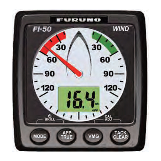
FI-501 WIND ANGLE FI-502 CLOSE HAULED WIND ANGLE The FI-501 Wind Angle and FI-502 Close Hauled Wind Angle instru- ments provide precise analog wind angle together with digital speed in- dication, in true or apparent direction. Wind speed is displayed in knots, meters/second or as a Beaufort scale number. -
Page 10: Turning The Power On/Off
1. FI-501 WIND ANGLE, FI-502 CLOSE HAULED WIND ANGLE Turning the Power On/Off To power the instrument, press the MODE key. All LCD segments go on and off and then the last-used display appears. To power off the instrument, press the MODE and APP/TRUE keys to- gether. -
Page 11: Display Layout
The pointer shows the true or apparent wind direction. The apparent wind scale range for the FI-501 is 360 (0 -179 starboard, 180 -359 port) and the FI-502 gives an indication of -60 to +60 , about the port and starboard of your boat. -
Page 12: Selecting A Display
1. FI-501 WIND ANGLE, FI-502 CLOSE HAULED WIND ANGLE Selecting a Display Press the MODE key to select a display. Each press of the key changes the display in the sequence shown below. Wind speed 12.5 Beaufort wind 13.5 speed... -
Page 13: Selecting Apparent Or True Wind Angle, Wind Speed
1. FI-501 WIND ANGLE, FI-502 CLOSE HAULED WIND ANGLE Beaufort no. and wind speed Wind speed Wind speed Beaufort Beaufort 0-0.2 28-33 14.4-17.4 0.5-2.0 34-40 17.5-21.0 2.1-3.5 41-47 21.1-24.6 7-10 3.6-5.6 48-55 24.7-28.8 11-16 5.7-8.6 56-63 28.9-32.6 17-21 8.7-11.2 32.7-32.9 22-27 11.3-14.3... -
Page 14: Displaying Velocity Made Good (Vmg) Information
1. FI-501 WIND ANGLE, FI-502 CLOSE HAULED WIND ANGLE Displaying Velocity Made Good (VMG) Information VMG is the actual vessel speed after adjusting for such factors as current and wind. Use the VMG key to display and erase VMG information and current dis- play alternately. -
Page 15: Alarms
1. FI-501 WIND ANGLE, FI-502 CLOSE HAULED WIND ANGLE Alarms There are four conditions which trigger audio and visual alarms: Maxi- mum true wind speed, Low true wind speed, High apparent wind angle, and Low apparent wind angle. 1. Press the MODE key to select desired alarm page, referring to the illustration below. -
Page 16: Operating Controls
FI-505 COURSE PILOT The FI-505 Course Pilot provides compass heading, in digital format. In the locked mode, steering error to ±30° deviation of locked course head- ing is shown, with the analog pointer. In the unlocked mode the pointer is set to zero. In the locked mode, the pointer shows course error;... -
Page 17: Turning The Power On/Off
2. FI-505 COURSE PILOT Turning the Power On/Off To power the instrument, press the MODE key. All LCD segments go on and off and then the last-used display appears. To power off the instrument, press the MODE and ENT keys together. The timer appears and counts down from three seconds to one second, and then the power goes off. -
Page 18: Selecting A Display
2. FI-505 COURSE PILOT Selecting a Display Press the MODE key to select a display, and the selection changes in the sequence shown below. If no heading data is available, three dashes ap- pear on the digital display. If you prefer to show ROT and COG (instead of heading and COG), press all four keys simultaneously until you hear a beep. -
Page 19: Unlocked And Locked Heading Modes
2. FI-505 COURSE PILOT Unlocked and Locked Heading Modes In the unlocked mode, the digital display Unlocked heading shows the current heading, true or magnetic, 135 ° and the pointer is at zero. The unit always starts up in the unlocked mode. In the locked mode, the operator sets a fixed (locked) heading, with the arrow keys. -
Page 20: Fi-506 Rudder
FI-506 RUDDER The FI-506 Rudder displays rudder angle, in analog indication. The pointer shows the rudder position in real time. The instrument’s scale range is -40° to +40° about zero. The FI-506 operates in real time, thus almost no action is required of the operator other than confirming the rudder angle and adjustment of the brilliance. -
Page 21: Turning The Power On/Off
3. FI-506 RUDDER Turning the Power On/Off To power the instrument, press the [ ] key. After the pointer moves to current rudder angle, release the key. To power off the instrument, press and hold down the [ ] key until the backlight goes off. -
Page 22: Maintenance,Troubleshooting
MAINTENANCE, TROUBLESHOOTING This chapter provides the information necessary for keeping your equip- ment in good working order. WARNING Do not open the equipment. Only qualified personnel should work inside the equipment. Preventive Maintenance Following the recommended procedures below will help maintain perfor- mance. -
Page 23: Troubleshooting
4. MAINTENANCE, TROUBLESHOOTING Troubleshooting If you feel the equipment is not functioning properly, follow the proce- dures in the table below to try to restore normal operation. If normal op- eration cannot be restored, do not attempt to check inside the cabinet. There are no user-serviceable parts inside. -
Page 24: Installation
Those items contain organic solvents that can damage coating and plastic parts, especially plastic connectors. Equipment Lists Standard supply for FI-501 WIND ANGLE Name Type Code No. Remarks Display Unit... - Page 25 5. INSTALLATION Standard supply for FI-506 RUDDER Name Type Code No. Remarks Display Unit FI-506 Installation CP26-00500 000-011-742 1 set See packing list at end of Materials manual for details. Optional supply Name Type Code No. Remarks Wind Transducer FI-5001 1 set For FI-502 Terminal Box...
-
Page 26: Mounting
5. INSTALLATION Mounting 5.2.1 Wind Transducer FI-5001 (for FI-501, FI-502) Installation site Fix the transducer to the mounting mast so that its mounting base is par- allel with the water line. Also, position the transducer so its leading edge faces the bow. - Page 27 Cable Tie (CV-150B) 6. Pass the cable assy. through the mast and connect it to the FI-501/FI- 502. If the connector of the cable cannot be passed through the mast (because mast diameter is too small), use the terminal box (supplied)
- Page 28 5. INSTALLATION 5.2.2 Display unit The display unit can be installed two ways: surface mount (two ways) or flush mount (optional kit required). This section covers surface mounting. For flush mounting, see the flush mounting instructions, issued separate- Surface mount 1: Fix instrument from front panel 1.
- Page 29 5. INSTALLATION Surface mount 2: Fix instrument from rear panel 1. Using the template at the back of this manual, open a mounting hole in the installation site. 2. Insert studs (M3x40, 2 pcs., supplied) in the holes shown below. (Use only the studs supplied.).
-
Page 30: Wiring
5. INSTALLATION Wiring For the service technician, detailed information about CAN bus wiring is on the FURUNO Tech-Net. See “Furuno CAN bus Network Design Guide” (TIE-00170-*). 5.3.1 Standalone configuration For standalone configuration the junction box is not necessary; connect the instrument directly to the power supply. - Page 31 5. INSTALLATION 2. Fabricate the above-mentioned cables as shown below. TERMINAL FI-50-SENSOR Cable FI-50-SENSOR Cable (from display unit) (from wind transducer) Twist shield. Twist shield. 3. Unfasten two self-tapping screws to remove the cover of the terminal box. 4. Connect the cables to the terminal inside the terminal box, referring to the interconnection diagram.
- Page 32 (0.3 m: Std, 1/5/10/20 m: Option) Cable Assy. FI-50-SENSOR-30/50 (30 m or 50 m) DISP. UNIT FI-503/FI-504/FI-505/FI-506/FI-507 DISP. UNIT (Instruments can be connected FI-501/FI-502 in any order.) Instruments chained FI-50-DROP Cable as above (6 m, standard supply) Instruments chained as above...
- Page 33 BACKBONE DROP DROP DROP 12 VDC CAN bus FI-501/502/503/504/505/506/507 Device Fix cable with cable tie (supplied). CN3 DROP - CN5 DROP and BACKBONE are socket-and-plug-type ter- minal blocks. Detach plug to connect wiring to it, by rocking it back and forth with your fingers.
- Page 34 5. INSTALLATION Terminal resistor The illustration below show various system configurations and what units to activate the terminal resistor. Smart sensor+FI-50x Smart FI-50x Sensor Multiple FI-50 series instruments, FI-5002, drop cabling FI-50x FI-50x FI-50x FI-50x Drop cable FI-5002 Multiple FI-50 series instruments, FI-5002 FI-50x FI-50x FI-50x FI-50x FI-5002...
- Page 35 Turn on the terminal resistor in the junction box when the NMEA 2000 sensor(s) connected to it do not have a terminal resistor. Terminal Resistor OFF: For how to turn on the terminal resistor in a FI-50 series instrument, see page 33 (FI-501//FI-502/FI-505) or page 35 (FI-506).
-
Page 36: Setting Up
CAL VMG Heading ref. VMG response Boat speed Pointer Wind speed on next tack response response response Setup1 menu items for FI-501, FI-502 LOC° LOCK Magnetic/true Pointer Heading indication selection alignment ROT response when ROT is selected for display. - Page 37 4th key: Increment value or select option. 4. To continue, press the MODE key to select another item. 5. To save settings and restore normal operation, press the 3rd and 4th keys together. Setup1 menu items for FI-501, FI-502 Setting range or Default Display...
- Page 38 5. INSTALLATION Setup1 menu items for FI-505 Menu item Setting range Default (in sequential Function or options setting order) Select bearing reference. MAG: Magnetic, TRUE: True Align pointer to zero. Operate the key or /CLEAR key until the pointer is at zero. Enables/disables use of locked heading.
- Page 39 5. INSTALLATION Setup2 menu The setup2 menu contains items which once preset do not require fre- quent adjustment. This menu is mostly operated the same as the setup1 menu. The only difference is how long the 3rd and 4th keys are pressed to activate the menu.
- Page 40 5. INSTALLATION Setup2 menu items Default Display Function Options setting Software version of CPU1. XX=program no. and x=program version no. Software version of CPU2. XX=program no. and x=program version no Key beep on/off. 1: ON, 0: OFF 1(ON Adjust brilliance automatically 1: ON, 0: OFF 1(ON) with environment.
- Page 41 5. INSTALLATION 5.4.2 Setting up FI-506 Rudder calibration You can apply an offset to the rudder indication to remove any deviation from actual and displayed rudder angles. 1. With the rudder centered, press the keys together until the instrument starts beeping continuously. The beeping indicates you have correctly enabled the calibration mode.
-
Page 42: Specifications
FI-501 WIND ANGLE/FI-502 CLOSE HAULED WIND ANGLE SPECIFICATIONS OF FI-501 WIND ANGLE FI-502 CLOSE HAULED WIND ANGLE GENERAL 1.1 Display Analog and segment LCD 1.2 Display Content Wind angle, wind speed, VMG, tack heading 1.3 Analog Meter Range ±180° (FI-501), ±60° (FI-502) 1.4 Analog Meter Accuracy... - Page 43 FI-505 COURSE PILOT SPECIFICATIONS OF FI-505 COURSE PILOT GENERAL 1.1 Display Analog and digital LCD 1.2 Display Content Heading 1.3 Analog Meter Display Range ±30° 1.4 Analog Meter Display Accuracy ±3° 1.5 I/O Port CAN bus, 2 ports JUNCTION BOX (OPTION) 2.1 No.
- Page 44 FI-506 RUDDER SPECIFICATIONS OF FI-506 RUDDER GENERAL 1.1 Display Analog 1.2 Analog Meter Display Range ±40° 1.3 Analog Meter Display Accuracy ±5° 1.4 I/O Port CAN bus, 2 ports JUNCTION BOX (OPTION) 2.1 No. of I/O ports CAN bus Device 6 ports CAN bus Backbone 2 ports...
-
Page 46: Packing List
PACKING LIST 26AA-X-9853 -2 FI-5001 N A M E DESCRIPTION/CODE № O U T L I N E Q'TY UNIT FI-5001 WIND TRANSDUCER 000-011-740-00 ACCESSORIES FP26-00201 FI-5001S-LOCK LOCK FITTINGS 000-171-683-10 INSTALLATION MATERIALS CP26-00201 4X20 SUS304 SELF-TAPPING SCREW 000-158-850-10 CV-150B CABLE TIE 000-167-183-10 DOCUMENT IMC-72661-* ワ/エイ... - Page 50 PACKING LIST FI-502 26AA-X-9858 -3 NAME OUTLINE DESCRIPTION/CODE № Q'TY NAME OUTLINE DESCRIPTION/CODE № Q'TY UNIT M3 SUS304 WING NUT FI-502 000-167-826-10 MONITOR UNIT DOCUMENT 000-011-741-00 INSTALLATION MATERIALS CP26-00500 OME-72660-* OPERATOR'S MANUAL 3X20 SUS304 000-166-982-1* SELF-TAPPING SCREW 000-163-884-10 OS*-72660-* OPERATOR'S GUIDE FI-50-CHAIN-0.3M 000-167-289-1* CABLE ASSEMBLY 0.3M...
- Page 51 PACKING LIST FI-505 26AA-X-9861 -3 NAME OUTLINE DESCRIPTION/CODE № Q'TY NAME OUTLINE DESCRIPTION/CODE № Q'TY UNIT M3 SUS304 WING NUT FI-505 000-167-826-10 MONITOR UNIT DOCUMENT 000-011-746-00 INSTALLATION MATERIALS CP26-00500 OME-72660-* OPERATOR'S MANUAL 3X20 SUS304 000-166-982-1* SELF-TAPPING SCREW 000-163-884-10 OS*-72700-* OPERATOR'S GUIDE FI-50-CHAIN-0.3M 000-167-292-1* CABLE ASSEMBLY 0.3M...
- Page 52 PACKING LIST FI-506 26AA-X-9862 -3 NAME OUTLINE DESCRIPTION/CODE № Q'TY NAME OUTLINE DESCRIPTION/CODE № Q'TY UNIT M3 SUS304 WING NUT FI-506 000-167-826-10 MONITOR UNIT DOCUMENT 000-011-747-00 INSTALLATION MATERIALS CP26-00500 OME-72660-* OPERATOR'S MANUAL 3X20 SUS304 000-166-982-1* SELF-TAPPING SCREW 000-163-884-10 OS*-72710-* OPERATOR'S GUIDE FI-50-CHAIN-0.3M 000-167-293-1* CABLE ASSEMBLY 0.3M...
- Page 53 FLUSH MOUNT KIT. FI-50 Q'TY OUTLINE NAME DESCRIPTIONS REMARKS ※1 TZ7580002A0 FRONT PANEL CODE NO. 000-167-885-10 PRE-ATTACHED TO ※1. 19-028-1502-0 FURUNO STICKER H3 CODE NO. 100-339-580-10 TZ7580007AO COVER CODE NO. 000-167-887-10 TZ7580008AO FRAME CODE NO. 000-167-886-10 3X20 SUS304 SELF-TAPPING SCREW CODE NO.
- Page 54 26/Oct/09 R.Esumi...
- Page 55 26/Oct/09 R.Esumi...
- Page 56 Sep.21'07 R.Esumi...
- Page 57 Jul.24'07 R.Esumi...
-
Page 58: Interconnection Diagram
WIND TRANSDUCER JUNCTION BOX INSTRUMENT FI-501/502 FI-5001/5001L LTWBD-06AFMM LTW12-05AFFM FI-5002 CAN bus WIND CN3 DROP_U LR7000 FI-50-SENSOR-30M/50M,30/50m,φ4.3 -SR7000 SHIELD SHIELD クロ CN1 12VDC FI-50-DROP,6m,φ6 FI-5002-POWERCABLE,2m 12VDC シロ WHT NET-S NET-S DIR1 チャ BRN (VV-SA0.75x2C) クロ NET-C NET-C DIR2 アカ SHIELD...
Need help?
Do you have a question about the FI-501 and is the answer not in the manual?
Questions and answers