
Related Manuals for Mako SROM1199


Summary of Contents for Mako SROM1199
-
Page 1: Instruction Manual
Instruction Manual 13MM DRILL PRESS Model SROM1199 Our tool range has you covered for DIY. Whatever the job, make light work of it with MAKO tools. -
Page 2: Product Features
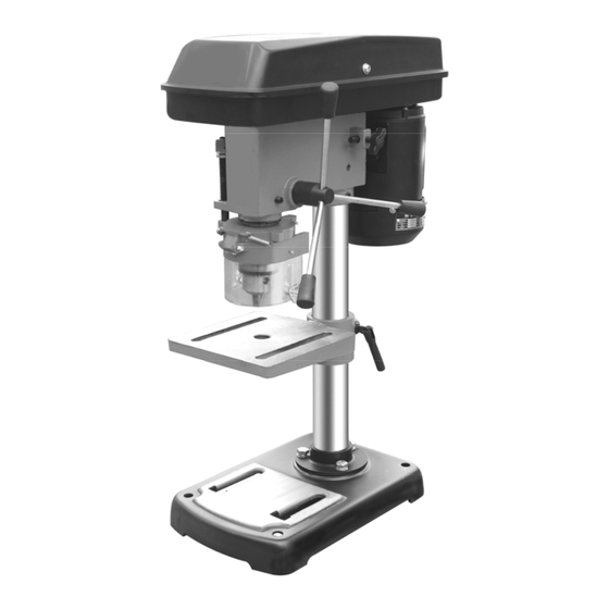
PRODUCT FEATURES: 1. Pulley Cover Feed Handle 2. Motor 10. Belt Tension Lock 3. Switch 11. Base 4. Chuck Guard 12. Head Assembly 5. Chuck 13. Column 6. Table 14. Base Bolts 7. Table Support 15. Depth Stop Assembly 8. Column Support... - Page 3 Mako 2 Year DIY Warranty: All Mako Power Tools are backed by a comprehensive 2 year DIY warranty. If for any reason you experience a fault with this power tool, please contact the retailer that it was purchased from, present the receipt and warranty card (at the back of the operating manual), for a full refund or replacement.
- Page 4 Work Area safety o Electrical Safety o Personal Safety o Power Tool Use and Care o Service Mako Drill Press Safety Instructions Mako Drill Press Operating Instructions Maintenance & Cleaning Mako Drill Press Technical Data...
-
Page 5: General Power Tool Safety Warnings
GENERAL POWER TOOL SAFETY WARNINGS: WARNING Read all safety warnings and all instructions. Failure to follow the warnings and instructions may result in electric shock, fire and/or serious injury. Save all warnings and instructions for future reference. The term "power tool" in the warnings refers to your mains-operated (corded) power tool or battery- operated (cordless) power tool. -
Page 6: Additional Safety Rules For Drill Presses
b) Do not use the power tool if the switch does not turn it on and off. Any power tool that cannot be controlled with the switch is dangerous and must be repaired. c) Disconnect the plug from the power source and/or the battery pack from the power tool before making any adjustments, changing accessories, or storing power tools. - Page 7 WARNING: DUST GENERATED FROM CERTAIN MATERIALS CAN HAZARDOUS TO YOUR HEALTH. ALWAYS OPERATE THE DRILL IN A WELL VENTILATED AREA. USE A DUST COLLECTION SYSTEM IF POSSIBLE WARNING: THE USE OF ANY ACCESSORY OR ATTACHMENT OTHER THAN ONE RECOMMENDED IN THIS INSTRUCTION MANUAL MAY PRESENT A RISK OF PERSONAL INJURY.
- Page 8 HEAD ASSEMBLY 1. Lift the Head Assembly (12) and slide it down the Column as far as it will go. Align the spindle with the centreline of the Base. 2. Secure the Head Assembly by tightening the grub screws on the right side of the housing – Fig 3. 3.
-
Page 9: Settings And Adjustments
SETTINGS AND ADJUSTMENTS. WARNING! During settings and adjustments, ensure that the drill press is disconnected from the power supply. TABLE HEIGHT ADJUSTMENT 1. Loosen the Table Support Clamp. 2. Slide the Table up or down the Column. Retighten the Clamp TABLE ANGLE ADJUSTMENT 1. -
Page 10: Maintenance
2. Switch the drill press OFF by pressing the red (O) button on the Switch. 3. Secure your workpiece to the table if possible, use a vice or clamps. DRILLING 1. Ensure the drill press is switched off and disconnected from the power supply. 2. -
Page 11: Technical Data
TECHNICAL DATA 13mm DRILL PRESS SROM1199 Rated Voltage 230V, 50Hz Input Power 350W 620, 920, 1280, 1750, Unloaded Speed 2620min 13mm Chuck Capacity Drilling Capacity - wood 20mm Drilling Capacity - steel 13mm Manufactured in China for The Warehouse Limited...
Need help?
Do you have a question about the SROM1199 and is the answer not in the manual?
Questions and answers