Table of Contents
Advertisement
Quick Links
Advertisement
Table of Contents

Summary of Contents for FDS FD215CV-C-TS
- Page 1 Revision Date: Rev: Document Number: 01/10/2017 MAN – FD215CV-C-TS (-1) Page 1 of 16 Installation and Operation Manual FD215CV-C-TS FD215CV-C-TS-1 21.5” LCD Touchscreen Display TECHNICAL SUPPORT © 2017 FDS Avionics Corp. All Rights Reserved. 470-239-7421 or FDSAvionics.com...
-
Page 2: Specifications
Revision Date: Rev: Document Number: 01/10/2017 MAN – FD215CV-C-TS (-1) Page 2 of 16 Specifications FD215CV-C-TS FD215CV-C-TS-1 Display Panel Technology 21.5” TFT Color LCD 21.5” TFT Color LCD Color 16.7 Million Colors 16.7 Million Colors Native Resolution 1920 x 1080... - Page 3 Revision Date: Rev: Document Number: 01/10/2017 MAN – FD215CV-C-TS (-1) Page 3 of 16 Connectivity * NTSC or PAL ** Touchscreen Controller TECHNICAL SUPPORT © 2017 FDS Avionics Corp. All Rights Reserved. 470-239-7421 or FDSAvionics.com...
-
Page 4: Table Of Contents
Revision Date: Rev: Document Number: 01/10/2017 MAN – FD215CV-C-TS (-1) Page 4 of 16 Table of Contents General Information ...................... 5 Front View ........................5 Additional Information ....................5 Installation Instructions ....................6 Power and Ground Wiring .................... 6 VGA Wiring ........................6 Pinouts ........................ -
Page 5: General Information
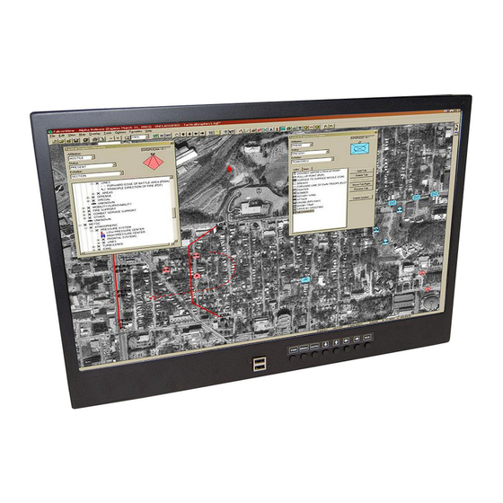
Document Number: 01/10/2017 MAN – FD215CV-C-TS (-1) Page 5 of 16 General Information The FD215CV-C-TS(-1) is a touchscreen enabled, special mission, high resolution, panel mounted 21.5” widescreen LCD. Front View Additional Information The LCD features include: Five video source inputs are available to include: 1. -
Page 6: Installation Instructions
Use (6) 8-32 Machine screws. See the technical drawing on page 13 for mounting locations and details. All cabin equipment, such as the FD215CV-C-TS(-1), should be installed on a non-essential bus and have a dedicated circuit breaker. It is a requirement that a switch be installed in the cockpit so that the pilot can de-energize the system should it become necessary. -
Page 7: Pinouts
Revision Date: Rev: Document Number: 01/10/2017 MAN – FD215CV-C-TS (-1) Page 7 of 16 Pinouts for FD215CV-C-TS (-1) Pinout for 28V PWR – D38999 connector (supplied) Mating Connector P/N: D38999/26FB5SA or Equivalent Crimp Contacts P/N: M39029/56-351 or Equivalent MATING FACE... - Page 8 Revision Date: Rev: Document Number: 01/10/2017 MAN – FD215CV-C-TS (-1) Page 8 of 16 Pinout for Touchscreen Control (DB-9F) Connector P/N: M24308/2-281 or Equivalent Crimp Contacts P/N: M39029/63-368 or Equivalent Description FD215CV-C-TS FD215CV-C-TS-1 +5V POWER (FROM USB SOURCE) RS-232 TX (Connect to Pin 2 on STD DB9...
- Page 9 Revision Date: Rev: Document Number: 01/10/2017 MAN – FD215CV-C-TS (-1) Page 9 of 16 Pin out for HD-SDI Input (Standard BNC – 75 OHM) - Supplied Description Center Video Signal Shell Video Return Pin out for HD-SDI Output (Standard BNC – 75 OHM) - Supplied...
- Page 10 Revision Date: Rev: Document Number: 01/10/2017 MAN – FD215CV-C-TS (-1) Page 10 of 16 Pin out for DVI-D Accepts a standard DVI-D (Single Link) male connector (supplied) View into mounted receptacle Description Number TMDS data 2- TMDS data 2+ TMDS data 2 shield...
-
Page 11: Operation Instructions
No pilot or aircrew action is necessary during flight or ground operation. The operator will be able to change the video output from the FD215CV-C-TS(-1) using the video source select button on the display. When applying 28VDC power, the display will turn on and look for a valid input on the last known source. -
Page 12: Touchscreen Driver
Follow the web address above and select the operating system depending on the platform that will be connected to the FD215CV-C-TS (-1). Any of the MT7 drivers should work for either the FD215CV-C-TS or FD215CV-C-TS-1 as long as the correct operating system was selected. -
Page 13: Technical Drawing
Revision Date: Rev: Document Number: 01/10/2017 MAN – FD215CV-C-TS (-1) Page 13 of 16 Technical Drawing TECHNICAL SUPPORT © 2017 FDS Avionics Corp. All Rights Reserved. 470-239-7421 or FDSAvionics.com... -
Page 14: Technical Support
01/10/2017 MAN – FD215CV-C-TS (-1) Page 14 of 16 Technical Support Should you have any questions concerning this product or other FDS Avionics Corp. products, please contact our Product Support representatives at (470) 239-7421. FDS Avionics Corp. 6435 Shiloh Road... -
Page 15: Warranty
Page 15 of 16 Warranty Information All FDS Avionics Corp. (FDS) products are warranted to be free from material or manufacturing defects for a period of 24 months from the date of shipment for General Aviation customers or 12 months from the date of shipment for Government/Special Mission customers. -
Page 16: Log Of Revisions
Page 16 of 16 Log of Revisions Date Page Description 12/06/2012 Initial Release Added provision for FD215CV-C-TS-1 RS232 Version. 10/06/2015 Updated Format, Warranty, Specifications Changed Company Name and Formatting – No Revision 1/10/2017 Change Necessary. TECHNICAL SUPPORT © 2017 FDS Avionics Corp.

Need help?
Do you have a question about the FD215CV-C-TS and is the answer not in the manual?
Questions and answers