Table of Contents
Advertisement
Quick Links
Advertisement
Table of Contents

Subscribe to Our Youtube Channel
Summary of Contents for LION CEBR2 Series
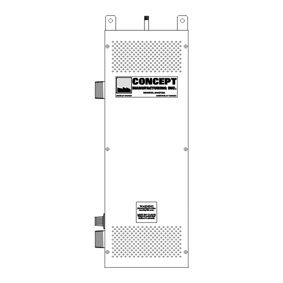
- Page 1 Warning: Use only water or an appropriate antifreeze. Do not use any other liquids especially methanol, automotive antifreeze or any kind of oil. Do not exceed 50% antifreeze. LION BOILERS CEBR2 Series Boiler Installation Manual CEBR2 V7.0 Printed in Canada...
-
Page 3: Before You Begin
Before You Begin Please read this manual thoroughly before you begin. If you encounter problems please see the troubleshooting section near the end of this manual. This boiler should only be installed and tested by qualified personnel with experience in hydronic heating systems, and electrical installations. -
Page 4: Outdoor Reset Control
Outdoor Reset Control This model also has Outdoor Reset control. An outdoor temperature sensor is used to monitor the outside temperature. The electronic controls then regulate the water temperature based on both the aquastat setting and the outside temperature to fine tune the boilers heat output. -
Page 5: Specifications
Specifications Model Volts Phase Amps Minimum Breaker Size Wire Size (Amps) CEBR2-3 12.5 CEBR2-5 20.8 CEBR2-6 CEBR2-8 33.3 CEBR2-9 37.5 CEBR2-10 41.7 CEBR2-12 CEBR2-15 62.5 CEBR2-18 CEBR2-19 79.2 CEBR2-20 83.3 CEBR2-23 95.8 CEBR2-24 CEBR2-25 104.2 CEBR2-28 116.7 CEBR2-208-9 CEBR2-208-11 11.25 208 31.2 CEBR2-208-15 14.7 40.8... -
Page 6: System Design
New Boiler Inspection All Boilers are inspected and tested at the factory prior to shipment. On receipt of your new boiler, be sure to check for any damage that may have occurred during shipping. Any such damage should be reported to the carrier immediately. Never install a damaged boiler. -
Page 7: Mechanical Installation
Installation Location (1) The site selected for installation of your boiler should leave at least 24” of clear space in front of the unit. The sides require only enough room for plumbing and electrical connections (see Fig. 2). The rear of the unit is considered as a “Zero Clearance”... -
Page 8: Pump Installation
(7) An expansion tank must be installed (see Fig. 3) to allow for water expansion as the system is heated. Dissimilar Metals Do not connect dissimilar metals on the inlet and outlet nipples. Dielectric Unions should be used. Another solution is to use brass or cast iron fittings between the boiler and any copper fittings that you may be using. - Page 9 Thermostat Anticipators The thermostat anticipator setting recommended is 0.2 amps. Failure to correctly adjust this setting may result in unsatisfactory comfort conditions, and could result in damage to the thermostat. This setting may have to be adjusted slightly to ideally match the boiler control system to the thermostat, as well as overcome the normal inertia of the radiation system.
-
Page 10: Maintenance
Start Up A new system must be thoroughly cleaned, flushed and drained, then refilled with clean water. Foreign material circulating through the system could be detrimental to the pump and to the heat transfer efficiency of the system and may lead to future problems. -
Page 11: Troubleshooting Guide
Troubleshooting Guide Problem Correction Boiler not heating, water cool. Check power supply, fuses or breakers. Check thermostat setting. Check temperature control on side of boiler. Boiler heating pipes cool. Check for air in system. Check pump circulation. Check all valves. Check for flow stoppage, or air locks. - Page 12 Concept Manufacturing Inc. Limited Warranty Concept Manufacturing Inc. (the "Manufacturer") warrants its Hydronic Boiler (the "Boiler") to be free from defects in material and workmanship under normal use and maintenance for a period of two (2) years from the date of original installation. The Manufacturer further warrants the tank to be free from defects in material and workmanship under normal use and maintenance for an additional eight (8) years for a total of ten (10) years from the date of original installation.
- Page 13 5. Damage as a consequence of misapplication, abuse, improper servicing, unauthorized alteration, improper operation or usage contrary to the Manufacturer's direction, design or specifications, as to any and all of which the Manufacturer shall be the sole judge; 6. Damage as a consequence of electrical surges, inadequacy or interruption of electrical services or corrosion, whether caused by chemicals or the environment;...
- Page 20 Troubleshooting Step By Step Procedure The following is a step by step procedure to help in troubleshooting any problems with this boiler. These steps should be preformed only by qualified personnel with experience in hydronic heating systems, and electrical heating equipment. You are working with high voltages and should be extremely careful.
- Page 21 (5) When the relay is energized, it will supply 120 volt power for running the pump, and activate the control board. a) There should now be 120 volt AC power to the terminals labeled P2L and P2N, as “STAT 2” has the jumper wire connected. b) If there is no power, replace the relay.
- Page 22 connected to that element. b) If there is power to the elements, but no heat, then with the all the power disconnected to the boiler, check the resistance of each element with an ohm meter, and replace any elements, as necessary. If you have gone through the above steps, and the boiler is still not working, please contact us for assistance.

Need help?
Do you have a question about the CEBR2 Series and is the answer not in the manual?
Questions and answers