Table of Contents

Related Manuals for TubeDepot 18 WATT

Summary of Contents for TubeDepot 18 WATT
- Page 1 Learn Build Play assembly video ASSEMBLY MANUAL for the Classic “ ” style 18 WATT TUBE GUITAR AMP KIT (with some great “ ” style mods) Version 20 01 August 2016 1686 Barcrest Dr., Memphis, TN 38134 www.tubedepot.com...
- Page 2 The Author, Publisher or Seller assume no liability with respect to the use of the information contained herein. For permission and other rights under this copyright, contact TubeDepot.com. TubeDepot.com...
-
Page 3: Table Of Contents
C) Amplifier Care and Feeding …..............D) How to Swage Fit Turrets – pictorial ............E) How to Press Fit Turrets – pictorial …............F) Turret Board Drilling Templates (separate 8.5 x 14 page). See our website for these form(s) - http://tubedepot.com/kit-british18whead.html TubeDepot.com... -
Page 4: Preface
With the introduction of a small 18 watt combo in the mid 60's, Marshall took a simple circuit, a great looking cabinet loaded with Celestion speakers, and built an amplifier legendary for great tone. -
Page 5: Chapter 1 Safety
- DISCLAIMER - TubeDepot.com, it's employees, officers, shareholders, investors and subsidiaries accept no liability for any damage(s), injury(s) or death incurred from or while building or using this kit. -
Page 6: Tools And Supplies
As with any construction project, there are certain recommended tools and supplies. The following are the tools and supplies NOT provided with the kit but are needed for completion. These are expected to be provided by the builder. TubeDepot.com The following is our recommended list: part number... -
Page 7: Chapter 3 Parts Inventory
16 ea screw, zinc plated 6-32 x 1/4", phillips pan head BP-632-1/4 7 ea screw, zinc plated 6-32 x 3/8", phillips pan head BP-632-3/8 13 ea nuts, KEPS 6x32 BP-632-KEPS 2 ea nuts, 6x32 BP-632-NUT 4 ea standoff, aluminum hex, #6 threaded, 3/4" long BP-ALSTDOFF-6-FF TubeDepot.com... - Page 8 2 ea 33.2K, 1/2W metal film resistor, 1% MIL-SPEC R-CMF60-33.2K 1 ea 47.5K, 1/2W metal film resistor, 1% MIL-SPEC R-CMF60-47.5K 2 ea 68.1K, 1/2W metal film resistor, 1% MIL-SPEC R-CMF60-68.1K 5 ea 100K, 1/2W metal film resistor, 1% MIL-SPEC R-CMF60-100K TubeDepot.com...
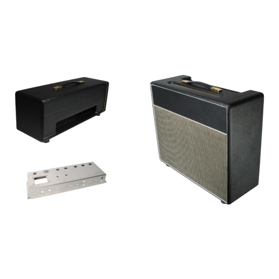
- Page 9 1X12 cabinet option (various speakers available) 1 ea cabinet, 1x12, Marshall style CAB-MAR18 4 ea flat washer, #8 BP-832-SAE 1 ea 1/4" plug, Switchcraft 280 P-280 2 ft tech flex, 1/4", yellow TS-PTNO-1-4-yellow 1 ea heat shrink, 3/8" BLACK, 6" length TS-HS-3-8 TubeDepot.com...
- Page 10 1 ea cabinet, micro box black vinyl, Marshall style CAB-MAR18-HEAD Tremolo hi / lo Speed Selection Mod 1 ea Switch, mini-toggle SPDT on-off-on P-108-MINI-1 1 ea 470K, 1/2w metal film, 1%, 500V rated R-CMF60-470K 1 ea 1M, 1/2w metal film, 1%, 500V rated R-CMF60-1M TubeDepot.com...
-
Page 11: Chapter 4 Cabinet Preparation
(photo 4.2a). Step 3 – Make a mark through each of the four photo 4.2a mounting holes of the chassis onto the cabinet TubeDepot.com... - Page 12 Step 10 – Drill a small 1/8” pilot hole in the center of each of the four marks. Step 11 – Drill the final 9/32” hole in each of these four pilot holes and remove the masking tape. Step 12 – Test fit the chassis to the cabinet and make any adjustments as needed. TubeDepot.com...
- Page 13 1/8” the photo 4.3d photo 4.3c entire length. Step 6 – Remove the backing from the final shielding tape strip and apply the tape to the TubeDepot.com...
- Page 14 Step 8 – Install the remaining 3” heat shrink length over the tech flex at the opposite end of the twisted pair near the cut end. Step 9 – Shrink the heat shrink in place with a heat gun. photo 4.3c TubeDepot.com...
- Page 15 Step 3 – Install a single #8 flat washer on each of the four mounting screws prior to installation. Step 4 – Install the four mounting screws through the speaker mounting holes into the baffle board. Firmly tighten down. photo 4.4a TubeDepot.com...
-
Page 16: Chassis Preparation And Assembly
Step 4 – Install a #8 standard nut on each of these bolts and firmly tighten. Make sure that the #8 solder terminals remain in position while tightening. Step 5 – Install a #8 KEPS nut on the remaining transformer bolt and firmly tighten. TubeDepot.com... - Page 17 Step 6 - Insert the tube socket from the outside of the chassis and rotate the socket so that pin 6 of the tube is closest to the chassis edge / corner. Step 7 – Mount the tube socket with two 6-32 x 3/8” screws (photo 5.6e). TubeDepot.com...
- Page 18 Step 2 – Install one fiber washer and a grounding washer on the second vibrato channel high sensitivity jack and install this jack with these washers into the chassis above the previous TubeDepot.com...
- Page 19 Wiring the power transformer filament center tap Step 1 – Locate the green wire with the yellow stripe on it coming from the power transformer. Step 2 – Cut this wire to a 3” length and strip and tin the end. TubeDepot.com...
- Page 20 Step 15 – Strip and tin the red wire and insert into pin 9 of V2. Do not solder just yet. Step 16 – Position the black wire against the chassis and re-twist the black wire around the red wire as needed to maintain uniformity. TubeDepot.com...
- Page 21 (along with previous wire) in pin 4 & 5 of V3. Step 39 – Neatly run this black wire back over to the chassis edge and form a 90 degree angle in the black wire at the chassis edge. Lay the remaining wire pair in this corner chassis TubeDepot.com...
- Page 22 V5 tube socket. Step 56 – Run the twisted pair over to the center line of the V5 tube socket and put a 90 TubeDepot.com...
- Page 23 Step 5 – Untwist the wire ends and so that one end reaches terminal 1 and the other red wire reaches terminal 7 of the V6 socket. Trim wire to the appropriate lengths (photo 5.11a). TubeDepot.com...
- Page 24 Step 1 – Cut a short 1” length of 20AWG buss wire (photo 5.15a). Step 2 – Install a short 1/2” length of salvaged insulation over this wire. Step 3 – Tack solder this jumper in place between pins 3 and 8 of V2. photo 5.15a TubeDepot.com...
- Page 25 Step 2 – Press The AC entry receptacle firmly into the square cut out in the rear plate and chassis until it “snaps” into place. The assembly video shows installing a different type of AC entry receptacle. These snap-in NOTE types are easier to use and the solder contacts are larger. TubeDepot.com...
- Page 26 Step 11 – Cut the black wire with strip coming from the transformer from recpt. to appropriate length and Strip and tin the end. Step 12 – Solder this wire to the AC receptacle terminal nearest the photo 5.20b vibrato jack on the back of the AC receptacle. TubeDepot.com...
- Page 27 Cut to length and photo 5.22b strip and tin this end. Step 8 –Tack solder this wire in place to the can capacitor terminal nearest the AC receptacle. TubeDepot.com...
- Page 28 Step 5 – Tack solder this stripped wire through both “tip” terminals photo 5.25a of the footswitch jack (C). Step 6 – Strip and tin the other end of this 10” wire and tack solder it to pin 7 of V3. Run this wire neatly against the rear chassis edge. TubeDepot.com...
- Page 29 Step 14 – Solder the 16 AWG buss wire in the two remaining “tip” terminals. All eight terminals of the speaker output jacks should now be soldered (photo 5.26b). TubeDepot.com...
- Page 30 To ease the assembly of the normal channel input jacks, I recommend temporarily installing NOTE the jacks in the more spacious vibrato channel position for soldering and assembly. photo 5.28a photo 5.28b Step 1 – With the two normal jacks temporarily installed into the vibrato channel position, TubeDepot.com...
- Page 31 2 of V1 (photo 5.28d). Photo 5.28d shows a 10pfd silver mica cap between the input terminal 2 and ground. This is a great mod for reducing unwanted radio station reception in the amp. TubeDepot.com...
- Page 32 Step 8 – Insert the end of the 2 1/3” wire from terminal 2 of the nearby tone control along with the above 4” wire into terminal 1 of this volume control. Solder both wires into place. Step 9 – The remaining wires (as in the photo 5.30a) will come from the turret board later. TubeDepot.com...
- Page 33 Solder all terminals of this jack. Step 18 – Cut a length of 20AWG black wire 4 1/2” long and strip and tin one end. Step 19 – Solder the tinned end of this black wire to terminal 3 of the speed control. The TubeDepot.com...
- Page 34 - When the components have been successfully loaded into the turret board, remove the standoffs from the turret board and remount them in their original chassis locations. TubeDepot.com...
-
Page 35: Turret Board Assembly
Depending on the mounting method you choose to install the turrets, use either the #43 drill bit (for press fitting) or the 3/32” drill bit (for the swage fitting). Refer to the booklet NOTE “How to Make a Top Quality Turret Board” ( http://site.tubedepot.com/pdf/turret_boards_v1.pdf) to decide which method is best for you. TubeDepot.com... - Page 36 Refer to the booklet “How to Make a Top Quality Turret Board” NOTE (http://site.tubedepot.com/pdf/turret_boards_v1.pdf) for detailed instructions on installing the turrets into the board. Step 1 – Using the method of your choice (press fitting or swage fitting), install the turrets in the appropriate holes of the board making sure that the turrets are mounted on the correct side of the board.
- Page 37 Step 2 – Hook this loop on turret T6 and solder in place (photo 6.7a). Step 3 – Extend this wire 3/4” from the turret, past the board edge and photo 6.7a make a sharp 90° bend in the wire toward the opposite end of the board. TubeDepot.com...
- Page 38 Step 2 – On the back side of the board, solder this wire into the opposite end of turret T49. Step 3 – Run the above wire directly to turret T41 and carefully trim this wire, leaving enough end to insert into back of T41 turret. TubeDepot.com...
- Page 39 The MIL-SPEC resistors used with this kit are rated at 1% and often have very specified NOTE values. As example, 475K is used in place of 470K; 825 in place of 820; etc. These specific values are within the ratings of the vintage 10% common resistors. photo 6.9a TubeDepot.com...
- Page 40 Step 19 – Install an 8.25KΩ resistor between turret T27 and T28. Solder at T27. Step 20 – Install a 2.2MΩ resistor between turret T28 and T29. Solder at T28. Step 21 – Install a 475KΩ resistor between turret T30 and T31. Solder at T30. TubeDepot.com...
- Page 41 Step 44 – Install a 1KΩ/2W metal oxide resistor between turrets T53 and T54. Solder these two metal oxide resistors in place at all four turrets (T51 – T54) (photo 6.9h). Step 45 – Install a 150Ω/10W wire wound resistor between turrets T55 and T56. Solder at TubeDepot.com...
- Page 42 Step 8 – Cut a 3 1/2” length of red 20AWG wire and solder to terminal T20 as above. photo 6.10d photo 6.10e Step 9 – Cut a 3 1/2” length of red 20AWG wire and solder to terminal T22 as above. TubeDepot.com...
- Page 43 Step 27 – Cut a 3” length of white 20AWG wire and solder to terminal T51 as above. Step 28 – Cut a 3” length of white 20AWG wire and solder to terminal T53 as above. Step 29 – Cut a 3” length of yellow 20AWG wire and solder to terminal T55 as above. photo 6.10h TubeDepot.com...
- Page 44 (photo 6.10g). Step 35 – Solder the above black 18AWG wire to the mounting tab of the fuse holder. (See completed board photo 6.10h) TubeDepot.com...
-
Page 45: Chassis And Turret Board Assembly
Step 3 – Locate the 20AWG black wire attached to the tremolo channel volume control (photo 7.6a). Step 4 – Strip and tin this wire and solder it to the signal buss ground nearest turret T30 (photo 7.3a) Wiring Tremolo Control Grounds to the Signal Buss Ground TubeDepot.com... - Page 46 Step 6 – Strip and tin the end of the yellow wire coming from terminal T28 and solder it to terminal 2 of the tremolo intensity control (photo 7.6a). Step 7 – Strip and tin the end of the orange wire from terminal T32 and solder it to terminal 2 of the tremolo speed control (photo 7.6a). TubeDepot.com...
- Page 47 T59, the other wire on the turret T60. Step 8 – Locate the two twisted green filament wires from the power transformer. Step 9 – Neatly run these two wires from the power transformer to T59 and T60 on the turret board. TubeDepot.com...
- Page 48 Step 6 – Solder this wire to terminal 3 of tube V3 tube socket. Step 7 – Strip and tin the end of the red 20AWG wire from turret T35. Step 8 – Solder this wire to terminal 6 of tube V3 tube socket. TubeDepot.com...
- Page 49 Step 5 – Strip and tin the end of the black 18AWG wire connected to the other end of the fuse holder (photo 7.15b). Step 6 – Solder this black 18AWG wire to the chassis ground nearest the can cap (photo 7.15c). photo 7.15c TubeDepot.com...
-
Page 50: Chapter 8 Testing
Step 5 – With your multimeter on the 20 VAC scale (this is the only AC measurement we will be making), put the two meter leads on turrets T59 photo 8.1a and T60 (polarity is not important). TubeDepot.com... - Page 51 Step 2 – Plug the amplifier's AC power cord into the AC power source at the wall. Step 3 - The panel indicator should illuminate. Monitor for any unusual smoke or smells or blown fuses. If anything unusual occurs, disconnect power photo 8.3b Photo 8.3a immediately and review connections. TubeDepot.com...
- Page 52 Step 2 – Turn the normal channel volume control clockwise and listen for a low level hiss from the speaker. There may be a slight hum too, but any dramatic hum indicates wiring troubles. Step 3 – If the above hiss is heard, turn the volume control back to minimum (leave tone TubeDepot.com...
- Page 53 - If the amp “clicks” in rhythm with the tremolo speed, then I recommend moving the wires around similar to the above technique. The tremolo oscillator signal is very strong and will bleed into neighboring audio wires if the wires are too close. TubeDepot.com...
-
Page 54: Chapter 9 Amp Final Assembly
Step 9 – Connect the 1/4” plug from the speaker in the cabinet to the speaker jack of the chassis. Make sure that the proper impedance on the amp is selected for the impedance of the speaker. THE END Step 10 – Your amp is done and ready for you to play. TubeDepot.com... -
Page 55: Schematics, Templates, And Parts Layout Schematic, 12Ax7 Input
Schematics, Templates, And Parts Layouts Visit our website to download high resolution versions of these drawings, schematics, and diagrams. TubeDepot.com... -
Page 56: Schematic, Ef86 Input
Visit our website to download high resolution versions of these drawings, schematics, and diagrams. TubeDepot.com... -
Page 57: Wiring And Parts Layout, 12Ax7
Wiring and Layout Template - 12AX7 input tube Visit our website to download high resolution versions of these drawings, schematics, and diagrams. TubeDepot.com... -
Page 58: Wiring And Parts Layout, Ef86
Wiring Template - EF86 input tube Visit our website to download high resolution versions of these drawings, schematics, and diagrams. TubeDepot.com... -
Page 59: Chapter 11 Cool Modifications
33K each. Two 68K resistors will function too but with a slight reduction in sensitivity gain. The EF86 adds a very “shimmering” high end quality to the tone where as the 12AX7 has a very “vocal” midrange quality. drawing 11b TubeDepot.com... -
Page 60: Selector Switch
Then wire the SPST toggle switch between the conjunction of the diodes and the output of the rectifier tube. drawing 11f drawing 11g 9 pin tube Octal Tube TubeDepot.com... - Page 61 Other options are in place of one of the speaker jacks or drilling a dedicated hole. There are many master volume control options, however this version is my personal favorite. It is a bit complicated to wire but the sound is very good. TubeDepot.com...
- Page 62 T40. Step 17 – Solder the wire from pot terminal 5 to turret board turret T46. There are wire routing holes in the turret board for these wires (photo 11L – next page). TubeDepot.com...
- Page 63 Connect a 10pfd capacitor between pin 2 of the tube socket and the nearest chassis ground connection. This is for the 12AX7 input connect to tube. nearest chassis ground Master Volume (cont') TubeDepot.com...
-
Page 64: A) Resistor And Capacitor Codes
Below are photos and descriptions of various resistors that could be used in your project. Metal Oxide 2W Carbon Composition 1/2W Carbon Film 1/2W Metal Oxide 3W Metalized Film 1/2W Wire Wound 5W Carbon Composition 1W Wire Wound 8W Metal Oxide 1W TubeDepot.com... - Page 65 Below I've listed some of the more common codes that you are likely to come across. 20%, 10%, and 5% types Carbon Film Metal Oxide Carbon Composition Metalized Film 1% and 2% types TubeDepot.com...
- Page 66 2nd line: 160V = voltage rating (160V) 3rd line: 0834R = batch / date code 104 = .1ufd 684 = .68ufd 103 = .01ufd 223 = .022ufd 473 = .047ufd 102 = .001ufd 222 = .0022ufd 472 = .0047ufd TubeDepot.com...
-
Page 67: B) Soldering Hints
4. When applying the soldering iron to a connection to be made, it is important to lay the tip in such a position that the maximum surface area of the tip is against the connection. In this way, the maximum heat is transferred to the connection in the minimal amount of time. TubeDepot.com... - Page 68 (while still adhering to the solder) leaving no connection with the intended terminal. The solution is to always scrape the gold plating off of a potential connection, down to the base metal, prior to soldering. This will guarantee a faithful soldered connection. TubeDepot.com...
-
Page 69: C) Amplifier Care And Feeding
Rectifier tubes (with amp modification): – 5Y3GT - 5AX4 - 5CG4 - 5R4 - 5T4 – 5V4 - 5Z4 - 5AR4 - GZ30 - 6106 Applications The laboratory environment is nice, but life experiences are better. Time to play. TubeDepot.com... -
Page 70: D) How To Swage Fit Turrets - Pictorial
How to Swage Fit Turrets TubeDepot.com... -
Page 71: E) How To Press Fit Turrets - Pictorial
How to Press Fit Turrets TubeDepot.com...
Need help?
Do you have a question about the 18 WATT and is the answer not in the manual?
Questions and answers