Table of Contents
Advertisement
Quick Links
Advertisement
Table of Contents

Related Manuals for ABB TRIO-20.0/27.6-TL-OUTD


Summary of Contents for ABB TRIO-20.0/27.6-TL-OUTD
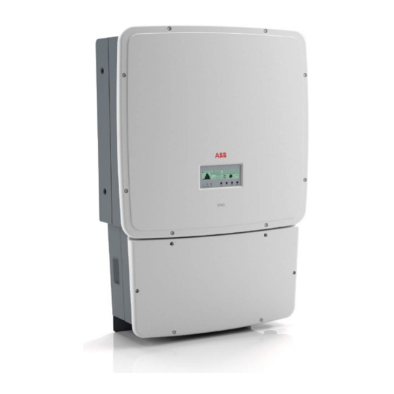
- Page 1 ABB solar inverters Product manual TRIO-20.0/27.6-TL-OUTD (20.0 to 27.6 kW)
-
Page 2: Important Safety Instructions
The manual must always accompany the equipment, even when it is transferred to another user. Operators are required to read this manual and scrupulously follow the indications reported in it, since ABB cannot be held responsible for damages caused to people and/or things, or the equipment, if the warranty conditions are not observed. - Page 3 3 - Safety and accident prevention 4 - Lifting and transport 5 - Installation 6 - Instruments 7 - Operation 8 - Maintenance TRIO-20.0-27.6-TL-OUTD-Product manual EN Rev E (M000001EG) EFFECTIVE 23/01/2014 © Copyright 2013 ABB. All Rights Reserved. - 3 -...
-
Page 4: Ntroduction And General Information
ABB accepts no liability for failure to comply with the instructions for correct installation and will not be held responsible for systems upstream or downstream the equipment it has supplied. -
Page 5: Table Of Contents
1- Introduction and general information ontents ntroduction and general information ....................4 Warranty and Supply Conditions ......................4 Not included in the supply .......................4 Contents ..............................5 Reference number index ........................9 Graphical representation of references ....................9 The document and who it is for ......................10 Purpose and structure of the document ................10 List of annexes ........................10 Staff characteristics .......................10... - Page 6 1- Introduction and general information afety and accident prevention ..................... 36 Safety instructions and general information ..................36 Hazardous areas and operations .......................37 Environmental conditions and risks ..................37 Signs and Labels ........................37 Thermal hazard ........................38 Clothing and protective devices for staff ................38 Residual risks ............................39 Table of residual risks ......................39 ifting and transport ........................
- Page 7 1- Introduction and general information 5 V auxiliary output connection .....................69 Serial Communication Connection (RS485) .................70 Monitoring and control systems ......................72 Procedure for connection to a monitoring system ..............73 Monitoring system via Aurora Communicator ...............74 Monitoring system via PVI-DESKTOP (Cabled) ..............74 Monitoring system via PVI-DESKTOP and PVI-RADIOMODULE ........75 Monitoring system via PVI-AEC-EVO ...................75 nstruments ............................
- Page 8 1- Introduction and general information Registration on “Registration” website and calculation of second-level password (Service Menu) ..............................119 Resetting the time remaining to change the grid standard ............122 Associating a “new component” after replacement ..............123 Replacing the string fuses (versions S2F / S2X) ................124 Replacing the back-up battery ......................125 Verification of ground leakage ......................126 Behaviour of a system without leakage ................126...
-
Page 9: Reference Number Index
1- Introduction and general information eference number index bracket service cable glands Input connectors (MPPT1) wiring box DC cable glands Input connectors (MPPT2) inverter jumpers anti-condensation valve cover DC input terminal board string fuses clamp screw AC+DC disconnect switch display handles DC overvoltage surge arresters keypad... -
Page 10: The Document And Who It Is For
1- Introduction and general information he document and who it is for urpose and structure of the document This operating and maintenance manual is a useful guide that will enable you to work safely and carry out the operations necessary for keeping the equipment in good working order. -
Page 11: Symbols Ad Signs
1- Introduction and general information ymbols ad signs In the manual and/or in some cases on the equipment, the danger or hazard zones are indicated with signs, labels, symbols or icons. Table: Symbols This points out that it is mandatory to consult the manual or original do- cument, which must be available for future use and must not be dama- ged in any way. -
Page 12: Field Of Use, General Conditions
1- Introduction and general information ield of use, general conditions ABB shall not be liable for any damages whatsoever that may result from incorrect or careless operations. You may not use the equipment for a use that does not conform to that provided for in the field of use. -
Page 13: Haracteristics
Characteristics eneral conditions A description of the characteristics of the equipment is given so as to identify its main components and specify the technical terminology used in the manual. Technical terminology and the fast retrieval system for information, are supported by: •... -
Page 14: Models And Range Of Equipment
2 - Characteristics odels and range of equipment The specific models of three-phase inverters that this manual is about are divided into two groups according to the maximum output power: 20kW or 27.6 kW. For inverters of equal output power, the variant between the various models is the layout of the wiring box The choice of model of inverter must be made by a qualified technician who knows about the installation conditions, the devices that will be installed outside the inverter and possible... -
Page 15: Identification Of The Equipment And The Manufacturer
3. Rating data 4. Certification marks DIN V VDE 0126-1-1 DIN V VDE 0126-1-1 PROTECTIVE CLASS: I PROTECTIVE CLASS: I Made in Italy Made in Italy www.abb.com/solar www.abb.com/solar MODEL: MODEL: SOLAR INVERTER TRIO-20.0-TL-OUTD-400 SOLAR INVERTER TRIO-27.6-TL-OUTD-400 N.B. The labels must NOT be 1000 V 400 V 3Ø... - Page 16 The officially required information is located on the approval label. The identification label is an accessory label which shows the information necessary for the identification and cha- racterisation of the inverter by ABB. If the service password is required, please use the details shown on the top label (inverter) N.B.
-
Page 17: Wiring Box Components
2 - Characteristics iring Box components For both models of inverter (20 kW or 27.6 kW), three wiring box are available with different layouts. tandard / -S2 Version TRIO-XX.X-TL-OUTD: Standard version wiring box TRIO-XX.X-TL-OUTD-S2: S2 wiring box version, like the basic version but with AC+DC disconnect switch Standard S2 Version... -
Page 18: S2X / -S2F Version
2 - Characteristics S2X / -S2F Version TRIO-XX.X-TL-OUTD-S2F: S2F wiring box version, with snap-together connectors, string fuses and AC+DC switch TRIO-XX.X-TL-OUTD-S2X: S2X wiring box version, more complete ver- sion with quick fit connectors, string fuses , DC overvoltage surge ar- resters , AC overvoltage surge arresters and AC+DC disconnect... -
Page 19: Principal Wiring Box Components
2 - Characteristics rincipal wiring box components AC+DC switch (wiring box S2 / S2F / S2X) Model: Telergon TFV1031E25501 or equivalent AC side Voltage Utilisation category Current 415Vac AC22A DC side (per individual input channel) Voltage Utilisation category Current 1000Vdc DC21B String fuses (wiring box S2F / S2X) -
Page 20: Characteristics And Technical Data
2 - Characteristics haracteristics and technical data Table: Technical Data TRIO-20.0-TL-OUTD TRIO-27.6-TL-OUTD Input Rated Input Power (P 20750 Wp 28600 Wp Maximum Input Power (P 22700 Wp 31000 Wp dcmax Rated Input Voltage (V 620 V Input Activation Voltage (V 360 V (adj. - Page 21 2 - Characteristics Table: Technical Data TRIO-20.0-TL-OUTD TRIO-27.6-TL-OUTD 50 Hz Rated Output Frequency (f 47...53 Hz Output Frequency Range (f ...f 22200VA 30000 VA Maximum apparent Output Power (S acmax is also guaranteed with cos(fi) = 0.9 The rated power P >0.995, adj.
-
Page 22: Tightening Torques
2 - Characteristics Table: Technical Data TRIO-20.0-TL-OUTD TRIO-27.6-TL-OUTD Isolation Level Transformerless Marking EN 50178, EN 62109-1, EN 62109-2, AS/NZS3100, Safety and EMC Standard AS/NZS 60950, EN61000-6-2, EN61000-6-3, EN61000-3-11, EN61000-3-12 1. The AC voltage range may vary depending on specific country grid standard 2. -
Page 23: Bracket Dimensions
2 - Characteristics racket dimensions The overall dimensions are expressed in mm and in inches 991.91mm 39.05’’ 978.9mm 38.54’’ 730.41mm 28.75’’ 554.9mm 21.84’’ 382.63mm 15.06’’ 164.36mm 6.47’’ 18mm 0.7’’ 25mm 0.98’’ - 23 -... -
Page 24: Efficiency Curves
2 - Characteristics fficiency curves The equipment was designed in consideration of current energy conser- vation standards, to avoid waste and unnecessary leakage. Graphs of the efficiency curves of all models of inverter described in this manual are shown below. The efficiency curves are linked to technical parameters that are continually being developed and improved and should therefore be considered approximate. -
Page 25: Power Derating
2 - Characteristics ower derating In order to allow inverter operation in safe thermal and electrical condi- tions, the unit automatically reduces the value of the power fed into the grid. Power limiting may occur due to: • Adverse environmental conditions (thermal derating) •... -
Page 26: Derating Due To The Altitude Of The Installation
2 - Characteristics erating due to the altitude of the installation The graphs show the derating as a function of the altitude of the instal- Derating Pout Vs Altitude lation. TRIO-20.0-TL-OUTD-400 Altitude Vs Normalized working temperature TRIO-20.0-TL-OUTD-S2-400 TRIO-20.0-TL-OUTD-S2F-400 TRIO-20.0-TL-OUTD-S2X-400 TRIO-27.6-TL-OUTD-400 TRIO-27.6-TL-OUTD-S2-400 TRIO-27.6-TL-OUTD-S2F-400 TRIO-27.6-TL-OUTD-S2X-400... - Page 27 2 - Characteristics TRIO-20.0-TL-OUTD-400 Pin and Pout Vs. Vin1/Vin2 TRIO-20.0-TL-OUTD-S2-400 Independent input configuration (max channel unbalance) TRIO-20.0-TL-OUTD-S2F-400 25000 TRIO-20.0-TL-OUTD-S2X-400 Pout Vs Vin 20000 Pin1 (8750max) Vs Vin1 Pin2 (12000Wmax) Vs Vin2 15000 10000 5000 1000 Vin [V] TRIO-27.6-TL-OUTD-400 Pout Vs. Vin TRIO-27.6-TL-OUTD-S2-400 Parallel input configuration TRIO-27.6-TL-OUTD-S2F-400...
-
Page 28: Characteristics Of A Photovoltaic Generator
2 - Characteristics haracteristics of a photovoltaic generator A PV generator consists of an assembly of photovoltaic panels that tran- sform solar radiation into DC electrical energy and can be made up of: Strings: X number of PV panels connected in series Array: group of X strings connected in parallel trings and Arrays In order to considerably reduce the cost of installing a photovoltaic sy-... -
Page 29: Description Of The Equipment
2 - Characteristics escription of the equipment This equipment is an inverter that converts direct electric current from a photovoltaic generator into alternating electric current and feeds it into the national grid. Photovoltaic panels transform energy from the sun into direct current (DC) electrical energy (through a photovoltaic field, also called photovol- taic (PV) generator;... -
Page 30: Connection Of Several Inverters Together
A configuration program that can help to correctly size the photovoltaic system is available on the web site of ABB - 30 -... -
Page 31: Functionality And Components Of The Equipment
The feed-in management methods vary according to the country of in- stallation and the relevant grid companies. For detailed information about the parameters and characteristics of this function, please contact ABB directly. Limiting the active power fed into the grid... - Page 32 2 - Characteristics Monitoring surge arresters (S2X versions only) The inverter monitors the status of the surge arresters (both AC and DC) and generates a warning in the event of a fault (visible on the display). Data transmission and control The inverter or networks of several inverters can be monitored locally or remotely using an advanced communication system based on a RS-485 serial interface that can be configured to communicate using the proprie-...
-
Page 33: Topographic Diagram Of The Equipment
2 - Characteristics opographic diagram of the equipment The diagram shown is a topographic diagram of the operation of the in- verter. The main blocks are the input DC-DC converters (called “boosters”) and the output inverter. Both the DC-DC converters and the output inverter operate at a high switching frequency and so enable a compact size and relatively light weight to be achieved. - Page 34 2 - Characteristics - 34 -...
-
Page 35: Protective Devices
2 - Characteristics rotective devices nti-Islanding In the event of a local grid outage by the electricity company, or when the equipment is switched off for maintenance operations, the inverter must be physically disconnected safely, to ensure protection of people work- ing on the grid, all in accordance with the relevant national standards and laws. -
Page 36: Afety And Accident Prevention
ABB accepts no liability for failure to comply with the instructions for correct installation are cannot be held responsible for the systems upstream or downstream of the equipment it has supplied. -
Page 37: Hazardous Areas And Operations
These conditions are reported on the thecnical data and on installation chapter. ABB CANNOT be held responsible for disposal of the equipment: displays, cables, batteries, accumulators, etc., and therefore the customer must... -
Page 38: Thermal Hazard
ABB has eliminated sharp edges and corners, but in some cases it is not possible to do anything, and we therefore advise wearing the clothing and personal protective devices provided by the employer. -
Page 39: Residual Risks
3 - Safety and accident prevention esidual risks Despite the warnings and safety systems, there are still some residual risks that cannot be eliminated. These risks are listed in the following table with some suggestions to prevent them. able of residual risks RISK ANALYSIS AND DESCRIPTION SUGGESTED REMEDY Noise pollution due to installation in unsuitable environments or where... -
Page 40: Ifting And Transport
ABB usually stores and protects individual components by suitable means to make their transport and subsequent handling easier, but as a rule it is necessary to turn to the experience of specialized staff in change of loading and unloading the components. -
Page 41: List Of Components Supplied
4 - Lifting and transport ist of components supplied Supplied with the inverter are all the components required to correctly install and connect the inverter Components available for all models Q.ty Connector for connecting the configurable relay Connector for connecting the communication and control signals Male key TORX TX20 Two-hole gasket for M25 signal cable glands and cap 2 + 2... -
Page 42: Kit Of Recommended Spare Parts
4 - Lifting and transport it of recommended spare parts A list of spare parts that are compatible with the TRIO inverter and in stock at the ABB warehouse is given below. Code Description Quantity Kit of handles and eyebolts for lifting the in-... -
Page 43: Types Of Lifting
4 - Lifting and transport ypes of lifting Because of its weight, the inverter unit must be lifted by two people or alternatively using suitable lifting equipment. It is possible to fit 4 handles in the side holes provided, to make the inverter easier to handle. When using cables to lift, two eyebolts can be fitted (one on each side) using the upper holes only. -
Page 44: Nstallation
Installation eneral conditions Installation of the equipment is carried out based on the system and the place in which the equipment is installed; therefore, its performance depends on the correctness of the connections. Staff authorised to carry out the installation must be specialised and experienced in this job;... -
Page 45: Environmental Checks
5 - Installation nvironmental checks • Consult the technical data to check the environmental parameters to be observed (degree of protection, temperature, humidity, altitude, etc.) • The installation to direct sunlight must be avoid beacuse it may cause: - phenonmena of power limitation by the inverter (with consequent reduc- tion of energy production) - premature aging of electronic/electromechanical components - premature aging of mechanical components (gaskets) and user inter-... -
Page 46: Installation Position
5 - Installation nstallation position When choosing the place of installation, comply with the following condi- tions: • Install on a wall or strong structure suitable for bearing the weight. • Install in safe, easy to reach places. • If possible, install at eye-level so that the display and status LEDs can be seen easily. - Page 47 5 - Installation all mounting 10 x 10 mm Ø • Position the bracket perfectly level on the wall and use it as a drilling template. • Drill the 10 holes required using a drill with 10mm bit. The ho- les must be about 70mm deep.
- Page 48 5 - Installation • Hook the inverter to the bracket by inserting the head of the rear screws in the slots as shown in the figure. To make lifting easier, handles or eyebolts (M12) can be attached to the side holes pro- vided.
- Page 49 5 - Installation • Once the parts are connected, screw in the two connector screws situated inside the wiring box. • Anchor the inverter to the brack- et, tightening the locking screw located on the lower side. PO WE DO WN - 49 -...
-
Page 50: Operations Preparatory To Pv Generator Connection
All ABB string inverters marketed in Europe are equipped with a device for protection against ground faults in accordance with the safety stand- ard set in Germany by Standard VDE V 0126-1-1:2006-02 (please refer to section 4.7 of the Standard). - Page 51 B ground fault interrupter. In accordance with article 712.413.1.1.1.2 of Section 712 of IEC Standard 64-8/7, we hereby declare that, because of their construction, ABB inverters do not inject ground fault direct currents. The use of an AC type circuit breaker with differential thermal magnetic protection with trip- ping current of 300 mA is advisable so as to prevent false tripping, due to the normal capaci- tive leakage current of photovoltaic modules.
-
Page 52: Independent Or Parallel Input Channels Configuration
5 - Installation ndependent or parallel input channels configuration All versions of the inverter are equipped with two input channels (therefore with double maximum power point tracker MPPT) independent of each other, which can however be connected in parallel using a single MPPT. Strings of photovoltaic modules having the same type and number of panels in series must be connected to each single channel;... -
Page 53: Channel Configuration Examples
5 - Installation Channel configuration examples MPPT configu- PV generator characteristics Notes ration The photovoltaic generator consists A NECESSARY condition so that the two of strings having a different number MPPTs can be used in independent mode is for MPPT configu- of modules in series from each other. -
Page 54: Configuration Of Independent Channels (Default Configuration)
5 - Installation onfiguration of independent channels (default configuration) This configuration involves the use of the two input channels (MPPT) in independent mode. This means that the jumpers between the two channels (positive and negative) of the DC input terminal board must not be installed and that the switch a01 situated on the communication card... -
Page 55: Input Connection To The Pv Generator (Dc Side)
5 - Installation nput connection to the PV generator (DC side) Once the preliminary checks have been made and it has therefore been verified that there are no problems on the photovoltaic system, and once the channel configuration has been chosen (parallel or independent), the inputs can be connected to the inverter. -
Page 56: Connection Of Inputs On The S2F / S2X Model
5 - Installation onnection of inputs on the S2F / S2X model For string connections using the S2F / S2X wiring box, the quick fit con- nectors (multicontact or weidmuller) situated at the bottom of the mecha- nism are used. For each input channel, there are two groups of connectors: •... -
Page 57: Installation Procedure For Quick Fit Connectors
5 - Installation nstallation procedure for quick fit connectors On inverter models with which quick fit connectors are supplied, they may be supplied in two different types: CAUTION: To avoid damage to the equipment, when attaching cables, pay particular atten- tion to polarity. - Page 58 5 - Installation MULTICONTACT (or equivalents) Installation of Multicontact connectors requires crimping to be carried out with suitable equipment. - Strip the cable to which you want to apply the connector (after verifying that it complies with the connector limits) 4...6mm 5.5...9mm - Apply the terminal to the conductor using suitable crimping pliers...
-
Page 59: String Protection Fuses (-S2F / S2X Models Only)
5 - Installation tring protection fuses (-S2F / S2X models only) izing of fuses Correctly sizing the string fuses to be used for protection against re- turn currents is very important since it can significantly reduce the risk of fire and damage to the PV generator. A “return current” can be generated in the event of a fault and relevant short-circuit at the ends of one or more PV modules of the system;... - Page 60 - Increase in Isc as a result of high temperature in the PV module - Thermal derating of the fuse - Maximum return current of the installed PV modules ABB can supply fuse kits of different values Code Description Quantity...
-
Page 61: Grid Output Connection (Ac Side)
ABB inverters must be earthed via the terminal with the protective earth symbol ( ), using a cable with an appropriate conductor cross-section for the maximum ground fault current that the generating system might experience. -
Page 62: Characteristics And Sizing Of The Line Cable
5 - Installation haracteristics and sizing of the line cable The cross-section of the AC line conductor must be sized in order to prevent unwanted disconnections of the inverter from the grid due to max 35 mm high impedance of the line that connects the inverter to the power supply point;... -
Page 63: Connection To The Ac Side Terminal Board
5 - Installation onnection to the AC side terminal board To prevent electrocution hazards, all the connection operations must be carried out with the disconnect switch downstream of the inverter (grid side) open and locked. Be careful not to change round one of the phases with neutral! High leakage current. -
Page 64: Installation Of The Second Protective Earthing Cable
5 - Installation nstallation of the second protective earthing cable Should it be necessary to install a second protective earthing cable, fol- low the procedure described below: • From among the components supplied, find the M6 screw, the two knur- led washers and the cable lug •... -
Page 65: Communication Card
5 - Installation ommunication card CR2032 MEMORY CARD COUNTRY/LANG SEL PAR IND SERV NORM CARD TERM. RTD1 RTD2 RTD3 PT1000 RTD1 RTD2 RTD3 ALARM PT100 communication card Ref. Ref. Description inverter manual Switch for setting parallel-connected or independent input channels Connector for the installation of WIFI modules (NOT ACTIVE) J11 e J14 Connectors for radiomodule card installation... -
Page 66: Connections To The Communication Card
5 - Installation onnections to the communication card Each cable that must be connected to the communication card must go through the three service cable glands • One of size M25 that accepts a cable with cross-section of between 10mm and 17mm. Two-hole gaskets are supplied for insertion in the ca- ble gland, which allow two separate cables with cross-section of up to 6mm to go through. -
Page 67: Connecting Environmental Sensors
5 - Installation onfigurable Relay connection (ALARM) The inverter is equipped with a multifunction relay with configurable acti- vation. It can be connected with normally open contact (being connected between the NO terminal and the common contact C) and with normally CR2032 closed contact (being connected between the NC terminal and the com- MEMORY... -
Page 68: Specifications Of Environmental Sensors
If the analogue sensors require an external power supply, use terminals 24V (positive) and GND (negative) on connector a10. The maximum +24V auxiliary voltage output current is 300mA pecifications of environmental sensors Tables with the technical data of the main sensors marketed by ABB are shown below: Model Type Gain Offset... -
Page 69: Connection Diagrams For Environmental Sensors
5 - Installation onnection diagrams for environmental sensors Connection diagrams for the main sensors marketed by ABB are shown below: For non-conventional installations or additional information about the connections, please contact the technical support department. PVI-AEC-T1000-BOX N.C. A1/A2 -Vcc_Heat -Vcc... -
Page 70: Serial Communication Connection (Rs485)
5 - Installation erial Communication Connection (RS485) There are two RS485 communication lines on the inverter: PC - dedicated line connecting the inverter to monitoring devices which use the proprietary communication protocol “Aurora” or to carry out firmware configuration and update operations using the configuration software “Aurora Manager LITE”. - Page 71 5 - Installation Table: crimping scheme connectors RJ45 Pin N° Function +T/R -T/R GND COM 1, 2, 4, 6, 8 not used Use a connector with metal body to provide cable shield continuity! For long distance connections, the connection on terminal connector is preferable using a shielded twisted pair cable with characteristic imped- ance of Z0=120 Ohm like the one shown in the following table: Signal...
-
Page 72: Monitoring And Control Systems
Depending on the device used monitoring can be local or remote. Here below are some of the main ABB monitoring devices: • Local monitoring - “PVI-USB-RS485_232” converter and a PC with “Aurora Communi- cator”... -
Page 73: Procedure For Connection To A Monitoring System
5 - Installation rocedure for connection to a monitoring system Connect all the units of the RS485 chain in accordance with the “daisy- chain” arrangement (“in-out”) observing the correspondence between signals, and activate the termination resistance of the communication line in the last element of the chain by switching switch a12 or a13 (to ON position) being careful to switch the switch of the serial line used (PC or PMU). -
Page 74: Monitoring System Via Aurora Communicator
RS485 PC For the same purpose, it is also possible to use equivalent devices which are on general sale, but, taking into account the fact that they have never been specifically tested, ABB cannot guarantee the correct operation of the connection. -
Page 75: Monitoring System Via Pvi-Desktop And Pvi-Radiomodule
USB 2.0 onitoring system via PVI-AEC-EVO The PVI-AEC-EVO is an ideal device for complete monitoring of ABB inverters. The device sends the data to the web portal where the data can be consulted remotely via online access. The main characteristics... -
Page 76: Nstruments
- there are doubts or contradictions between your experience, the manual and/or other operators. ABB cannot be held responsible for damage to the equipment or the operator if it is the result of incompetence, insufficient qualifications or lack of training. -
Page 77: Display And Keyboard
6 - Instruments isplay and keyboard isplay fields and symbols description Using the display, operating parameters for the equipment are shown. signals, alarms, channels, voltages, etc. The display, when in operation, behaves dynamically, allowing cyclical display of certain information (see relevant chapter). b02 b03 b04 Ref. -
Page 78: Description Of Keyboard And Led Panel
6 - Instruments escription of keyboard and LED Panel Using the combination of keyboard keys, under the display, it is possible to set values or scroll through the data items to view them. LED indica- tors are located alongside the keyboard, indicating the operating state of the inverter. -
Page 79: Peration
Operation eneral conditions Before checking the operation of the equipment, it is necessary to have a thorough knowledge of the INSTRUMENTS chapter and the functions that have been enabled in the installation. The equipment operates automatically without the aid of an operator; operating state is controlled through the instruments. -
Page 80: Monitoring And Data Transmission
PC (using signal converter PVI-USB-RS485_232) or a data logger with an RS-485 port (PVI-DESKTOP / PVI-AEC-EVO). Con- tact the ABB support service with any queries about device compatibility. ypes of data available The inverter provides two types of data, which can be retrieved through the special interface software and/or the display. -
Page 81: Preliminary Operations Before Commissioning
7 - Operation reliminary operations before commissioning In order to commission the inverter it is necessary to carry out certain preliminary operation to ensure the inverter operates properly. rid standard setting of the country and language display There are different grid parameters (dictated by the electricity distributor) according to the country in which the inverter is installed. -
Page 82: Grid Standard Of The Country And Display Language Saving
7 - Operation Switch Country Grid Standard Display Displayed language name TURKEY HV @400V ENGLISH TURKEY HV CEI-016 @ 400V ITALIAN CEI 016 EN50438 generic @ 400V ENGLISH EN 50438 The list of grid standards given in the table was valid at the time of issue of the manual. It will be continually updated as new country standards with which the inverter is compatible are introduced If the grid standard for the country of installation is not on the list, its pre-... -
Page 83: Checking The Polarity Of The Strings (Models S2F And S2X Only)
7 - Operation hecking the polarity of the strings (models S2F and S2X only) Inside the wiring box installed in inverter models S2F and S2X there are two boards on which the string fuses are installed The board that is positioned horizontally at the bottom of the wiring box contains the safety fuses on the positive poles of the strings con- nected in input, whereas the board that is installed vertically houses the negative string fuses. - Page 84 7 - Operation 4. Enable the string polarity test using the advanced configuration sof- tware “Aurora Manager LITE” using the Tab Partner Device > Fuse Con- trol Board > Global Settings > DC strings self-test and selecting “Test enabled”. Please refer to the “Aurora Manager LITE” configuration software manual. Once the Self-test function has been enabled the inverter will automati- cally start checking the polarity of the strings.
-
Page 85: Installing The Wiring Box Cover
7 - Operation nstalling the Wiring Box cover When you have finished connecting and configuring the inverter, and before you start it up, you must install the Wiring Box cover. During installation of the cover, perform the operations listed in order and use the specified torque for tightening the 6 screws (show in the technical data section) to maintain the in- IP65 verter’s IP level... -
Page 86: Commissioning
7 - Operation ommissioning Do not place objects of any kind on the inverter during operation! Do not touch the heatsink while the inverter is operating! Some parts may be very hot and cause burns. b02 b03 b04 NOTE: Before proceeding with commissioning, make sure you have carried out all the checks and verifications indicated in the section on preliminary checks. - Page 87 7 - Operation • At this point the b17 icon will flash, this indicates the start-up of the DC- DC circuit (booster) part. This icon will remain permanently switched on when the DC-DC will be operating at steady state (the flashing of the icon usually lasts a few seconds).
-
Page 88: Display Access And Settings
7 - Operation isplay access and settings After the commissioning of the inverter, it is possible/necessary to set the configuration of the inverter by accessing the “Account Settings” from the display. The following are the main adjustable parameters (see the section dedicated to the “Menu descriptions”) •... -
Page 89: Dynamic Behaviour Of The Display
7 - Operation ynamic behaviour of the display • If the MPPT scan function is enabled, icon b9 will be shown on the dis- play. See configuration in the MPPT settings menu section. This icon will flash during scanning. • During operation, the following values are displayed in rotation: - Voltage and current (b15 and b16) from the PV generator. -
Page 90: Led Behaviour
7 - Operation ED behaviour = LED On The following table shows all the possible activation combinations of LEDs = LED flashing on the LED panel according to the operating status of the inverter. = LED Off = Any one of the conditions described above LED status Operating state... -
Page 91: Specifications On The Behaviour Of The Leds
7 - Operation pecifications on the behaviour of the LEDs Next to each state of the inverter, indicated through the steady or inter- mittent lighting of the relevant LED, a message that identifies the opera- tion it is carrying out or the detected fault/anomaly is also shown on the display , section b10, (see relevant chapter). -
Page 92: Description Of The Menus
7 - Operation escription of the menus The display has a section b10 (graphic display) for moving through the menu using the buttons of the LED panel Section b10 consists of 2 lines with 16 characters per line and can be used to: •... - Page 93 7 - Operation Errors/Warnings Errors/Warnings EXXX Inverter OK Inverter status. The code for any malfunction will be displayed. Lun 22 Lug 15:55 Lun 22 Lug 15:55 Date and time as set on the inverter DOWN DOWN P/N: Product identification code P/N -3xxx- S/N: Sequential serial number S/N XXXXXX...
-
Page 94: Statistics Menu
7 - Operation tatistics menu Selecting STATISTICS from the three main sub-menus gives access to: Statistics ENTER Lifetime DOWN Partial DOWN Today DOWN User period 1. Lifetime This section of the menu allows you to display the Total statistics: • Time: Total operating time •... -
Page 95: Settings Menu
7 - Operation ettings menu When SETTINGS is selected from the three main sub-menus, the first screen for the password is displayed in the display. The default password is “0000”. This can be changed using the display buttons, always following the same procedure: •... - Page 96 7 - Operation 1. Address This section of the menu allows you to set the address for the serial com- munication of single inverters connected to the RS485 line. The addresses that can be assigned are 2 to 63. Use the UP and DOWN buttons to scroll the numerical scale.
- Page 97 We advise changing the activation voltage only if really necessary and to set it to the correct value: the photovoltaic generator sizing instrument available on the Internet site of ABB indi- cates whether it is necessary to change the Vstart and the value to set.
- Page 98 7 - Operation 8. Autotest This section of the menu is available only for the Italian country standard. Refer to the section on this topic in the manual. 9. Alarm This section of the menu allows you to set the activation status of a relay (available either as contact normally open –...
- Page 99 7 - Operation INVERTER RUN • Configurable alarm with reset at the end of the alarm signalling N.C. process (display text “Alarm (Conf.)”) Relay State: Idle N.O. The relay is activated (state: switched) whenever an error is present (code Exxx) or a warning (code Wxxx) from those selected from the list in SELECTED ERROR/WARNING the dedicated submenu.
- Page 100 Under Voltage limit (set at 70% of Vstart). ABB sets the time at 60 sec. The user can set it at any time from 1 to 3600 sec.
- Page 101 7 - Operation UP / DOWN arrows). When it has been enabled, Load std curve will appear on the display, allowing you to set the following control curve(*): Q/Pn 0.36 (*) The curve can be edited with the Aurora Manager LITE configu- ration software -0.1 -0.2...
-
Page 102: Info Menu
7 - Operation nfo Menu Selecting INFO from the three main sub-menus gives access to: Information ENTER Product ID DOWN Serial No. DOWN Firmware DOWN Country Select. DOWN Fuse Control 1. Product ID Displays the model code 2. Serial No Displays the serial number and week and year of manufacture of the equipment 3. -
Page 103: Autotest Procedure In Accordance With Standard Cei 0-21
7 - Operation UTOTEST procedure in accordance with standard CEI 0-21 The autotest run in accordance with grid standard CEI-021 may be initia- ted from the display menu or by using an RS485/USB converter with the dedicated interface software (Aurora Communicator). The conditions required to perform an Autotest are: •... - Page 104 7 - Operation Test in corso The display shows the message “Performing Test” when the test has ..started. At the end of the test, when the inverter has disconnected from the grid, the results and values of the test performed will appear on the display. You can move from one screen to another using the UP/DOWN arrow keys.
-
Page 105: Turning Off The Inverter
7 - Operation urning off the inverter Some parts may be very hot and could cause burns. Some inverter parts may be subject to voltages that could be hazardous for the operator. Before performing any work on the inverter, follow the procedure for turning off the inverter. tandard Wiring Box Version •... -
Page 106: Wiring Box Versions S2, S2F And S2X
7 - Operation iring Box Versions S2, S2F and S2X • Put the AC+DC switch14 in the OFF (open) position. Under this condition the wiring box has hazardous voltages, identi- fied by the colours RED (up to 1000 V DC) and ORANGE (400V AC). Green areas may be freely accessed. -
Page 107: Aintenance
Maintenance eneral conditions Checking and maintenance operations must be carried out by specialized staff assigned to carry out this work. Maintenance operations must be performed with the apparatus disconnected from the grid (power switch open) and the photovoltaic panels obscured or isolated, unless otherwise in- dicated. -
Page 108: Routine Maintenance
PV plant. We recommend that maintenance operations be carried out by qualified personnel or by the personnel of ABB (as set forth in a maintenance contract). The periodicity of the maintenance operations may vary in accordance with local environmen-... - Page 109 8 - Maintenance - Code on display - Error message Name of Alarm and Cause Solution - Signal • Measure the insulation resistance using a megohmmeter posi- tioned in the photovoltaic field (positive terminal short-circuited at the negative pole) compared to ground. The measurement is strongly influenced by the environmental conditions, so must be - No code Ground fault of photovoltaic generator:...
- Page 110 8 - Maintenance - Code on display - Error message Name of Alarm and Cause Solution - Signal - W010 * Fan broken: • Error inside the inverter and cannot be checked externally. - Fan broken! This error occurs when there is a malfunction in the fan/ Yellow LED lamp.
- Page 111 8 - Maintenance - Code on display - Error message Name of Alarm and Cause Solution - Signal • Check whether the composition of the PV generator enables Input over-current (photovoltaic generator): - E001 input current which exceeds the maximum threshold allowed by The alarm occurs when the inverter's input current the inverter and that the configuration of the inputs (independent - Input OC...
- Page 112 8 - Maintenance - Code on display - Error message Name of Alarm and Cause Solution - Signal • Check that the setting of the "IN MODE" switch is specifically Incorrect configuration of inputs (set in parallel ra- set to "PAR" and that the bridges between the two input channels ther than independent): have been included.
- Page 113 8 - Maintenance - Code on display - Error message Name of Alarm and Cause Solution - Signal Failure of the test on the inverter's relay (DC-AC cir- cuit): • Error inside the inverter and cannot be checked externally. Before connecting to the grid the inverter carries out in- - E021 ternal tests.
- Page 114 8 - Maintenance - Code on display - Error message Name of Alarm and Cause Solution - Signal High leakage current (DC side): Error in the internal measurement (made when the in- • Error inside the inverter and cannot be checked externally. - E030 verter is grid connected) of the leakage current of the - Error Meas Ileak...
-
Page 115: Power Limitation Messages
8 - Maintenance - Code on display - Error message Name of Alarm and Cause Solution - Signal • Check that the inverter is not exposed to direct sunlight. Wait for Excessive temperature measured inside the inver- E056 the temperatures to which the inverter is exposed to return to the ter's wiring box: - Over Temp. - Page 116 8 - Maintenance - Message on display Name of Derating and Cause Solution - Signal Anti-islanding power limitation: The message indicates that a power limitation is active since an "islanding" condition has been recorded. - LIMxxx% CODE:03 • If the inverter remains connected to the grid and LIM xxx% = Power reduction percentage the limitation is active, contact customer assistance Display symbol b6...
-
Page 117: Dismantling The Inverter
8 - Maintenance ismantling the inverter The inverter is composed of an Inverter part and a Wiring Box which may be dismantled separately. The paragraphs that follow describe dis- mantling procedures. Perform the steps for “Turning off the inverter” before dismantling one or both inverter parts. ismantling the inverter Procedure for dismantling the inverter part only: •... -
Page 118: Dismantling The Wiring Box
8 - Maintenance ismantling the Wiring Box Procedure for dismantling the Wiring Box only: • Slacken the 6 screws holding the cover of the Wiring Box • Remove all connecting cables coming from outside the box. • Slacken the two screws on con- nector inside the Wiring Box •... -
Page 119: Registration On "Registration" Website And Calculation Of Second-Level Password (Service Menu)
8 - Maintenance egistration on “Registration” website and calculation of second- level password (Service Menu) Settings In order to obtain the second-level password needed to access the in- ENTER Password 0000 verter's service menu, it is necessary to go through the following stages: ENTER Service ENTER... - Page 120 8 - Maintenance Stage 3 - Request for second level password - Go online and access https://registration.ABBsolarinverters.com - Insert the Username (corresponding to the email used during registra- tion) and the Password obtained at the end of Stage 2 - Access the section dedicated to requesting the second-level password - Choose the inverter model from the drop-down list and insert Update Ver., Serial Number and Week of Production of the inverter which were obtained previously (Stage 1)
- Page 121 8 - Maintenance - Click on icon to request password. Should there be an error in inputting data, the fields containing the error will be highlighted in red. If, on the other hand, the data are correct, the passwords will be shown in a new window and at the same time sent to the email address used for registration.
-
Page 122: Resetting The Time Remaining To Change The Grid Standard
8 - Maintenance esetting the time remaining to change the grid standard From the time a valid grid standard is entered and the inverter is turned on, a period of 24 hours is available to modify the grid standard setting. The 24 hours are counted only when the inverter is turned on. -
Page 123: Associating A "New Component" After Replacement
8 - Maintenance ssociating a “new component” after replacement The two parts that comprise the equipment (inverter and wiring box) are logically associated with one another. When the parts are dissocia- NEW SYSTEM PART ted from one another due to the wiring box or inverter being replaced REFUSED! (perhaps because of a failure, etc.), a message is displayed to indicate that the new component must be associated with the original part. -
Page 124: Replacing The String Fuses (Versions S2F / S2X)
8 - Maintenance eplacing the string fuses (versions S2F / S2X) Replacing the string protection fuses in inverter versions S2F/S2X may be necessary when: 1. Adjusting the fuse rating in relation to the type of PV panel utilized 2. The fuse is damaged Replacing the fuse is carried out by means of the specific fuse carrier which makes it simple to extract the fuse and correctly position the new fuse when it is inserted. -
Page 125: Replacing The Back-Up Battery
8 - Maintenance eplacing the back-up battery The back-up battery may need to be replaced when: 1. An error message is displayed 2. The date and time settings are reset CR2032 MEMORY CARD COUNTRY/LANG SEL The battery is of the CR2032 type and is installed on the communication PAR IND SERV NORM... -
Page 126: Verification Of Ground Leakage
8 - Maintenance erification of ground leakage In the presence of anomalies or report of ground fault (where provided), there may be a ground leakage from the PV generator (DC side). To check this, measure the voltage between the positive pole and ground and between the negative pole (of the PV generator) and ground using a voltmeter whose input accepts a voltage sufficient for the dimensions of the photovoltaic generator. -
Page 127: Behaviour Of A System With Leakage
8 - Maintenance ehaviour of a system with leakage If the voltage measured between one of the two poles and ground does not tend to 0V and stabilizes on a value, there is a ground leakage from the PV generator. Example: When the measurement is made between positive pole and ground, a voltage of 200V is measured. -
Page 128: Measuring The Insulation Resistance Of Photovoltaic Generator
8 - Maintenance easuring the insulation resistance of photovoltaic generator To measure the insulation resistance of the PV generator compared to ground , the two poles of the PV generator must be short-circuited (using a suitably sized switch). Once the short-circuit has been made, measure the insulation resistance (Riso) using a megohmmeter positioned between the two shorted poles and ground (of the inverter). -
Page 129: Storage And Dismantling
ABB CANNOT be held responsible for disposal of the equipment: displays, cables, batteries, accumulators, etc., and therefore the customer must dispose of these substances, which are potentially harmful to the environment, in accordance with the regulations in force in the country of installation. -
Page 130: Further Information
For more information on ABB products and services for solar applica- tions, navigate to www.abb.com/solarinverters - 130 -... -
Page 131: Contact Us
www.abb.com/solarinverters...
Need help?
Do you have a question about the TRIO-20.0/27.6-TL-OUTD and is the answer not in the manual?
Questions and answers