
Related Manuals for Panasonic Limux DMC-CM1P


Summary of Contents for Panasonic Limux DMC-CM1P
-
Page 1: Digital Camera
ORDER NO. DSC1504014CE Digital Camera DMC-CM1P Model No. DMC-CM1GC DMC-CM1GH DMC-CM1GN DMC-CM1GT Colour (S)...Silver Type © Panasonic Corporation 2015 Unauthorized copy- ing and distribution is a violation of law. -
Page 2: Table Of Contents
TABLE OF CONTENTS PAGE PAGE 1 Safety Precautions -----------------------------------------------3 1.1. General Guidelines ----------------------------------------3 1.2. Leakage Current Cold Check ---------------------------3 1.3. Leakage Current Hot Check (See Figure. 1)--------3 2 Warning --------------------------------------------------------------4 2.1. Prevention of Electrostatic Discharge (ESD) to Electrostatically Sensitive (ES) Devices ----------4 2.2. -
Page 3: Safety Precautions
1 Safety Precautions 1.1. General Guidelines 1.3. Leakage Current Hot Check (See Figure. 1) 1. IMPORTANT SAFETY NOTICE There are special components used in this equipment 1. Plug the AC cord directly into the AC outlet. Do not use which are important for safety. These parts are marked by an isolation transformer for this check. -
Page 4: Warning
2 Warning 2.1. Prevention of Electrostatic Discharge (ESD) to Electrostatically Sensitive (ES) Devices Some semiconductor (solid state) devices can be damaged easily by static electricity. Such components commonly are called Elec- trostatically Sensitive (ES) Devices. The following techniques should be used to help reduce the incidence of component damage caused by electrostatic discharge (ESD). -
Page 5: How To Replace The Lithium Ion Battery
2.2. How to Replace the Lithium Ion Battery Please refer to the disassembly procedure for replacement method. NOTE: This Lithium Ion battery is a critical component. It must never be subjected to excessive heat or discharge. It must therefore only be fitted in requirement designed specifically for its use. Replacement batteries must be of same type and manufacture. -
Page 6: Service Navigation
3 Service Navigation 3.1. Introduction This service manual contains technical information, which allow service personnel’s to understand and service this model. Please place orders using the parts list and not the drawing reference numbers. If the circuit is changed or modified, the information will be followed by service manual to be controlled with original service manual. 3.2. - Page 7 3.2.5. Notice of Main P.C.B. Unit replacement IMEI number is different for each Main P.C.B. Unit. Therefore, IMEI number label is shipped with the repair Main P.C.B. Unit. When replace the Main P.C.B. Unit, paste new IMEI number label on the paste position of the label of the Front Cover Unit. For more information, see the 7.3.2.
-
Page 8: General Description About Lead Free Solder (Pbf)
3.3. General Description About Lead Free Solder (PbF) The lead free solder has been used in the mounting process of all electrical components on the printed circuit boards used for this equipment in considering the globally environmental conservation. The normal solder is the alloy of tin (Sn) and lead (Pb). On the other hand, the lead free solder is the alloy mainly consists of tin (Sn), silver (Ag) and copper (Cu), and the melting point of the lead free solder is higher approx.30°C (86°F) more than that of the normal solder. -
Page 9: How To Define The Model Suffix
3.4. How to Define the Model Suffix There are two kinds of DMC-CM1 regardless of the colours. • a) DMC-CM1 (Japan domestic model), CM1GC/GH • b) DMC-CM1EB/EF/EG • c) DMC-CM1P • d) DMC-CM1GN • e) DMC-CM1GT 3.4.1. Defining methods: To define the model suffix to be serviced, refer to the nameplate in Front Cover Unit. NOTE: After replacing the Main P.C.B., be sure to achieve adjustment. -
Page 10: Specifications
4 Specifications The following specification is for DMC-CM1P. Some specifications may differ depending on model suffix. -
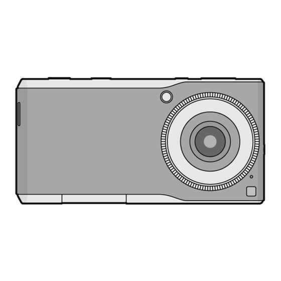
Page 12: Location Of Controls And Components
5 Location of Controls and Components The following description is for DMC-CM1P. Some descriptions may differ depending on model suffix. The page number in this chapter does not show the page number of this service manual. -
Page 13: Service Fixture & Tools
6 Service Fixture & Tools 6.1. Service Fixture and Tools The following Service Fixture and tools are used for checking and servicing this unit. 6.2. When Replacing the Main P.C.B. Unit After replacing the Main P.C.B. Unit, be sure to achieve adjustment. -
Page 14: Disassembly And Assembly Instructions
7 Disassembly and Assembly Instructions 7.1. Disassembly Flow Chart This is a disassembling chart. When assembling, perform this chart conversely. 7.2. P.C.B. Location... -
Page 15: Disassembly Procedure
7.3. Disassembly Procedure Item Fig. Removal LCD Module Unit, (Fig. D1) Front Cover Unit (Fig. D2) (Fig. D3) (Fig. D4) Cover Glass Tape Connector (A) LCD Module Unit Water Label CN Plate Unit Screw Spacer B × 2 Screw (A) × 6 Locking tab ×... - Page 16 7.3.1. Removal of the LCD Module Unit and Front Cover Unit (Fig. D2) (Fig. D1)
- Page 17 (Fig. D4) (Fig. D3)
- Page 18 7.3.2. Removal of the Lens Unit and Main P.C.B. Unit (Fig. D5) (Fig. D6)
- Page 19 7.3.3. Removal of the Main ANT Unit, Bat- 7.3.4. Removal of the Battery P.C.B. and tery, Sub FPC Unit and Back Case Control Ring Unit Unit (Fig. D8) NOTE: (When Installing) Make sure to confirm the following points when installing: •...
-
Page 20: Removal Of The Mos Unit
7.4. Removal of the MOS Unit 7.5. How to Use Servicing Tool for Assembling To prevent the MOS Unit from catching the dust and dirt, do not remove the MOS Unit except for replacing. 7.5.1. How to paste the Cover Glass Tape... - Page 21 7.5.2. How to install the LCD Module Unit...
-
Page 23: Measurements And Adjustments
8 Measurements and Adjustments 8.1. Matrix Chart for Replaced Part and Necessary Adjustment The relation between Replaced part and Necessary Adjustment is shown in the following table. When concerned part is replaced, be sure to achieve the necessary adjustment(s). As for Adjustment condition/procedure, see the “Adjustment method” which is available in Adjustment software. NOTE: After the adjustment is finished, that you do the following: -Execute from the home screen: [ Settings ] ... -
Page 24: Maintenance
9 Maintenance 9.1. Cleaning Lens and LCD Panel Do not touch the surface of lens, Viewfinder and LCD Panel with your hand. When cleaning the lens, use air-blower to blow off the dust. When cleaning the LCD Panel, dampen the lens cleaning paper with lens cleaner, and the gently wipe the its surface. Note: The Lens Cleaning Kit ;...
Need help?
Do you have a question about the Limux DMC-CM1P and is the answer not in the manual?
Questions and answers