
Related Manuals for Lenovo ThinkCentre M715q


Summary of Contents for Lenovo ThinkCentre M715q
- Page 1 User Guide and Hardware Maintenance Manual M715q Machine Type (MT): 10M2, 10M3, 10M4, 10M5 Energy Star MT: 10M2, 10M3, 10M4, 10M5...
-
Page 2: Table Of Contents
Contents Overview Front view 3 Rear view 4 System board 6 Machine type and model label 7 Locking the computer 8 Specifications 9 Replacing hardware Before replacing hardware 10 Handling static-sensitive devices 11 Understanding replaceable parts 12 Replacing customer-replaceable units (CRUs) Before replacing CRUs 13 Replacing CRUs Removing the computer cover 17... -
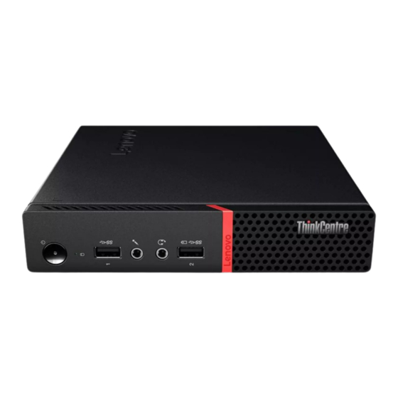
Page 3: Front View
Manager program and enable the function. To open the Power Manager program, see “Accessing a program on the computer” on page 38. To enable the Always On USB connector, refer to the help system of the Power Manager program. © Copyright Lenovo 2016. -
Page 4: Rear View
Overview Rear view Note Your computer model might look slightly different from the illustration. Wi-Fi antenna slot Used to install the rear Wi-Fi antenna cable connector that is optional. The rear Wi-Fi antenna is installed on the rear Wi-Fi antenna cable connector. Padlock loop Used to secure a padlock. - Page 5 Used to connect a device, such as a keyboard, mouse, scanner, printer, or PDA, that requires a USB 2.0 connection. USB 2.0 connector Used to connect a device, such as a keyboard, mouse, scanner, printer, or PDA, that requires a USB 2.0 connection. © Copyright Lenovo 2016.
-
Page 6: System Board
Overview System board Note for additional component descriptions. Front view Rear view M.2 Wi-Fi card slot Coin-cell battery SATA 3.0 storage drive connector System fan connector Optional serial connector Optional display connector M.2 storage drive slot Microprocessor socket Thermal sensor Cover presence switch connector (Intrusion switch connector) Internal speaker connector... -
Page 7: Machine Type And Model Label
Machine type and model label The machine type and model label identifies the computer. When you contact Lenovo for help, the machine type and model information helps support technicians to identify the computer and provide faster service. The machine type and model label is attached on the side of the computer as shown. -
Page 8: Locking The Computer
The cable lock also locks the buttons used to open the computer cover. This is the same type of lock used with many notebook computers. You can order such a cable lock directly from Lenovo by searching for Kensington at: http://www.lenovo.com/support. -
Page 9: Specifications
Ethernet LAN Network features Wireless LAN (optional) Bluetooth (optional) Width: 35 mm (1.4 inches) Physical dimensions Height: 179 mm (7.0 inches) Depth: 183 mm (7.2 inches) Maximum configuration as shipped: 1.3kg (2.9 lb) Weight (without the package) © Copyright Lenovo 2016. -
Page 10: Replacing Hardware
In most areas of the world, Lenovo requires the return of defective CRUs (Customer Replaceable Units). Information about this will come with the CRU or will come a few days after the CRU arrives. -
Page 11: Handling Static-Sensitive Devices
When this is not possible, place the static-protective package that the part came in on a smooth, level surface and place the part on the package. Do not place the part on the computer cover or other metal surface. © Copyright Lenovo 2016. -
Page 12: Understanding Replaceable Parts
CRU. Optional-service CRUs can be removed and installed by users or, during the warranty period, by a Lenovo service technician. Field-Replaceable Units (FRUs) FRUs are computer parts that a trained technician can upgrade or replace. -
Page 13: Vesa Mount Bracket
Self-service CRUs Power adapter bracket 2 2 2 Power adapter Power cord Computer cover Vertical stand Internal speaker Keyboard Mouse VESA® mount bracket External optical drive External optical drive box I/O box © Copyright Lenovo 2016. -
Page 14: System Fan
Optional-service CRUs Memory module System fan Wi-Fi card Coin-cell battery M.2 storage drive Storage drive bracket 2.5-inch storage drive... - Page 15 FRUs System board Microprocessor Internal speaker holder Heat sink Front Wi-Fi antenna Chassis Rear Wi-Fi antenna © Copyright Lenovo 2016.
- Page 16 Replacing a memory module 37 Replacing the coin-cell battery 39 Replacing the Wi-Fi card 41 Note To replace a component that is not in the list above, contact a Lenovo service technician. The support phone numbers are available at: http://www.lenovo.com/support/phone...
-
Page 17: Removing The Computer Cover
Hold the sides of your computer and gently lay it down so that the computer cover is facing up. Unlock any locking device that secures the computer cover. Remove the computer cover. © Copyright Lenovo 2016. -
Page 18: Replacing The Power Adapter
Replacing CRUs Replacing the power adapter Attention Do not open your computer or attempt any repairs before reading the Important Product Information Guide. Remove any media from the drives and turn off all connected devices and the computer. Then, disconnect all power cords from electrical outlets and disconnect all cables that are connected to the computer. -
Page 19: Replacing The Vertical Stand
Remove any media from the drives and turn off all connected devices and the computer. Then, disconnect all power cords from electrical outlets and disconnect all cables that are connected to the computer. Replace the vertical stand. Type1 © Copyright Lenovo 2016. - Page 20 Type2...
-
Page 21: Replacing The Vesa Mount Bracket
If the power adapter bracket is available, remove the power adapter bracket. See Replacing the power adapter bracket. Replace the VESA mount bracket. If the power adapter bracket is available, install the power adapter bracket. See Replacing the power adapter bracket. © Copyright Lenovo 2016. -
Page 22: Replacing The External Optical Drive
Replacing CRUs Replacing the external optical drive Attention Do not open your computer or attempt any repairs before reading the Important Product Information Guide. Remove any media from the drives and turn off all connected devices and the computer. Then, disconnect all power cords from electrical outlets and disconnect all cables that are connected to the computer. - Page 23 Connect the external optical drive adapter to the USB connectors on the external optical drive and the computer. © Copyright Lenovo 2016.
-
Page 24: Replacing The I/O Box
Replacing CRUs Replacing the I/O box Attention Do not open your computer or attempt any repairs before reading the Important Product Information Guide. Remove any media from the drives and turn off all connected devices and the computer. Then, disconnect all power cords from electrical outlets and disconnect all cables that are connected to the computer. -
Page 25: Replacing The Power-Adapter Bracket
Remove any media from the drives and turn off all connected devices and the computer. Then, disconnect all power cords from electrical outlets and disconnect all cables that are connected to the computer. Replace the power adapter bracket. © Copyright Lenovo 2016. -
Page 27: Replacing The Internal Speaker
Remove the computer cover. For details, see Removing the computer cover. Record the routing and connection of the internal speaker cable, and then disconnect the cable from the system board. Replace the internal speaker. © Copyright Lenovo 2016. - Page 28 Connect the cable of the new internal speaker to the internal speaker connector on the system board. Reinstall the removed parts and computer cover. For details, see Completing the parts replacement.
-
Page 29: Replacing The Wireless Mouse
Disconnect the USB dongle from your computer. Then, take away your failing wireless mouse. Remove the new wireless mouse from the package. Replace the wireless mouse. © Copyright Lenovo 2016. - Page 30 Notes The green LED indicates that the mouse is ready for use. The flashing amber LED indicates a low battery power level. Push the power switch to the off position when you are not using the mouse to extend the battery life.
-
Page 31: Replacing The Wireless Keyboard
Take away the USB dongle from the keyboard compartment or from the wireless mouse compartment and connect it to an available USB connector on the computer. Close the compartment cover. The keyboard is ready for use. © Copyright Lenovo 2016. -
Page 32: Replacing The System Fan
Replacing CRUs Replacing the system fan Attention Do not open your computer or attempt any repairs before reading the Important Product Information Guide. Remove any media from the drives and turn off all connected devices and the computer. Then, disconnect all power cords from electrical outlets and disconnect all cables that are connected to the computer. -
Page 33: Replacing The 2.5-Inch Storage Drive
Remove the computer cover. For details, see Removing the computer cover. Remove the storage drive bracket. Note Carefully handle the storage drive bracket to avoid breaking the front Wi-Fi antenna cable. © Copyright Lenovo 2016. - Page 34 Replace the 2.5-inch storage drive. Reinstall the storage drive bracket. Reinstall the computer cover and reconnect the cables. For details, see Completing the parts replacement.
-
Page 35: Replacing The M.2 Storage Drive
Remove the computer cover. For details, see Removing the computer cover. Remove the storage drive bracket. For details, see Replacing the 2.5-inch storage drive. Replace the M.2 storage drive. Type1 © Copyright Lenovo 2016. - Page 36 Type2 Reinstall the removed parts and computer cover, and then reconnect the cables. For details, see Completing the parts replacement.
-
Page 37: Replacing A Memory Module
Remove the computer cover. For details, see Removing the computer cover. Remove the storage drive bracket. For details, see Replacing the 2.5-inch storage drive. Replace the memory module. © Copyright Lenovo 2016. - Page 38 Reinstall the removed parts and computer cover, and then reconnect the cables. For details, Completing the parts replacement.
-
Page 39: Replacing The Coin-Cell Battery
Remove the computer cover. For details, see Removing the computer cover. Remove the storage drive bracket. For details, see Replacing the 2.5-inch storage drive. Replace the coin-cell battery. © Copyright Lenovo 2016. - Page 40 Reinstall the removed parts and computer cover, and then reconnect the cables. For details, Completing the parts replacement. To dispose of the coin-cell battery, refer to the “Lithium coin-cell battery notice” topic in the Safety and Warranty Guide.
-
Page 41: Replacing The Wi-Fi Card
Remove the computer cover. For details, see Removing the computer cover. Remove the storage drive bracket. For details, see Replacing the 2.5-inch storage drive. Remove the Wi-Fi card cover. Type1 © Copyright Lenovo 2016. - Page 42 Type2 Replace the Wi-Fi card. Type1...
- Page 43 Type2 Reinstall the Wi-Fi card cover. Type1 © Copyright Lenovo 2016.
- Page 44 Type 2 Reinstall the removed parts and computer cover, and then reconnect the cables. For details, Completing the parts replacement.
-
Page 45: Completing The Parts Replacement
Ensure that the cables are routed correctly before reinstalling the computer cover. Keep cables clear of the hinges and sides of the computer chassis to avoid interference when reinstalling the computer cover. Install the computer cover. © Copyright Lenovo 2016. - Page 46 Install the screw to secure the computer cover. If a locking device is available, use it to lock the computer. Reconnect the external cables and power cords to the corresponding connectors on the computer.
-
Page 47: Replacing Field-Replaceable Units (Frus)
Replace an FRU only with another FRU of the correct model. When you replace an FRU, ensure that the model of the machine and the FRU part number are correct by referring to the website: http://www.lenovo.com/serviceparts-lookup An FRU should not be replaced because of a single, unreproducible failure. - Page 48 Replacing FRUs Replacing the internal speaker holder Attention Do not open your computer or attempt any repairs before reading the Important Product Information Guide. Remove any media from the drives and turn off all connected devices and the computer. Then, disconnect all power cords from electrical outlets and disconnect all cables that are connected to the computer.
- Page 49 Remove the system fan. For details, see Replacing the system fan. Remove the internal speaker. For details, see Replacing the internal speaker. Remove the internal speaker holder. For details, see Replacing the internal speaker holder. Replace the heat sink. © Copyright Lenovo 2016.
- Page 50 Reinstall the removed parts and computer cover, and then reconnect the cables. For details, Completing the parts replacement.
- Page 51 Touch only the edges of the microprocessor. Do not touch the gold contacts on the bottom. Do not drop anything onto the microprocessor socket while it is exposed. The socket pins must be kept as clean as possible. © Copyright Lenovo 2016.
- Page 53 Reconnect all cables that were disconnected from the system board. For details, see System board. Reinstall the removed parts and computer cover, and then reconnect the cables. For details, Completing the parts replacement. © Copyright Lenovo 2016.
-
Page 54: Front Wi-Fi Antenna
Replacing FRUs Replacing the front Wi-Fi antenna Attention Do not open your computer or attempt any repairs before reading the Important Product Information Guide. Remove any media from the drives and turn off all connected devices and the computer. Then, disconnect all power cords from electrical outlets and disconnect all cables that are connected to the computer. - Page 55 Connect the front antenna cable to the Wi-Fi card. Reinstall the removed parts and computer cover, and then reconnect the cables. For details, Completing the parts replacement. © Copyright Lenovo 2016.
-
Page 56: Rear Wi-Fi Antenna
Replacing FRUs Replacing the rear Wi-Fi antenna Attention Do not open your computer or attempt any repairs before reading the Important Product Information Guide. Remove any media from the drives and turn off all connected devices and the computer. Then, disconnect all power cords from electrical outlets and disconnect all cables that are connected to the computer. -
Page 57: System Board
Remove the Wi-Fi card. For details, see Replacing the Wi-Fi card. Remove the microprocessor. For details, see Replacing the microprocessor. Record the cable routing and cable connections, and then disconnect all cables from the system board. © Copyright Lenovo 2016. - Page 58 Replace the system board. Note Carefully handle the system board by its edges. Route all the cables that you disconnected from the failing system board, and then reconnect the cables to the new system board. For details, see System board. Reinstall the removed parts and computer cover, and then reconnect the cables.
-
Page 59: Completing The Parts Replacement
Ensure that the cables are routed correctly before reinstalling the computer cover. Keep cables clear of the hinges and sides of the computer chassis to avoid interference when reinstalling the computer cover. Install the computer cover. © Copyright Lenovo 2016. - Page 60 Install the screw to secure the computer cover. If a locking device is available, use it to lock the computer. Reconnect the external cables and power cords to the corresponding connectors on the computer.
-
Page 61: Notices & Trademarks
Lenovo representative for information on the products and services currently available in your area. Any reference to a Lenovo product, program, or service is not intended to state or imply that only that Lenovo product, program, or service may be used. Any functionally equivalent product, program, or service that does not infringe any Lenovo intellectual property right may be used instead. - Page 62 Trademarks The following terms are trademarks of Lenovo in the United States, other countries, or both: Lenovo The Lenovo logo ThinkCentre ThinkCentre logo DisplayPort and VESA are trademarks of the Video Electronics Standards Association. Other company, product, or service names may be trademarks or service marks of others.
- Page 64 First Edition (October 2016) © Copyright Lenovo 2016 LIMITED AND RESTRICTED RIGHTS NOTICE: If data or software is delivered pursuant to a General Services Administration "GSA" contract, use reproduction, or disclosure is subject to restrictions set forth in Contract No GS-35F-05925...
Need help?
Do you have a question about the ThinkCentre M715q and is the answer not in the manual?
Questions and answers